EP1865505A1 - Verhinderung von Störungen durch konkurierende Signale bei der Ansteuerung einer H-Brücke eines Schwingspulenmotors - Google Patents
Verhinderung von Störungen durch konkurierende Signale bei der Ansteuerung einer H-Brücke eines Schwingspulenmotors Download PDFInfo
- Publication number
- EP1865505A1 EP1865505A1 EP06425391A EP06425391A EP1865505A1 EP 1865505 A1 EP1865505 A1 EP 1865505A1 EP 06425391 A EP06425391 A EP 06425391A EP 06425391 A EP06425391 A EP 06425391A EP 1865505 A1 EP1865505 A1 EP 1865505A1
- Authority
- EP
- European Patent Office
- Prior art keywords
- psm
- voice coil
- drive signals
- drive
- coil motor
- Prior art date
- Legal status (The legal status is an assumption and is not a legal conclusion. Google has not performed a legal analysis and makes no representation as to the accuracy of the status listed.)
- Granted
Links
- 230000002265 prevention Effects 0.000 title description 2
- 230000002708 enhancing effect Effects 0.000 claims abstract description 3
- 238000000034 method Methods 0.000 claims description 14
- 230000000737 periodic effect Effects 0.000 claims description 5
- 230000001360 synchronised effect Effects 0.000 claims description 2
- 238000013459 approach Methods 0.000 abstract description 3
- 230000010363 phase shift Effects 0.000 description 7
- 238000010586 diagram Methods 0.000 description 5
- 238000002347 injection Methods 0.000 description 5
- 239000007924 injection Substances 0.000 description 5
- 230000008901 benefit Effects 0.000 description 4
- 230000015556 catabolic process Effects 0.000 description 2
- 230000007423 decrease Effects 0.000 description 2
- 238000006731 degradation reaction Methods 0.000 description 2
- 238000001914 filtration Methods 0.000 description 2
- 238000012986 modification Methods 0.000 description 2
- 230000004048 modification Effects 0.000 description 2
- 230000003071 parasitic effect Effects 0.000 description 2
- 101100478187 Arabidopsis thaliana MOS4 gene Proteins 0.000 description 1
- 101100461812 Arabidopsis thaliana NUP96 gene Proteins 0.000 description 1
- 102100030393 G-patch domain and KOW motifs-containing protein Human genes 0.000 description 1
- 101001009694 Homo sapiens G-patch domain and KOW motifs-containing protein Proteins 0.000 description 1
- 101150090280 MOS1 gene Proteins 0.000 description 1
- 101100401568 Saccharomyces cerevisiae (strain ATCC 204508 / S288c) MIC10 gene Proteins 0.000 description 1
- 239000012141 concentrate Substances 0.000 description 1
- 230000001939 inductive effect Effects 0.000 description 1
- 229910052982 molybdenum disulfide Inorganic materials 0.000 description 1
- 230000002441 reversible effect Effects 0.000 description 1
- 238000004088 simulation Methods 0.000 description 1
- 230000002123 temporal effect Effects 0.000 description 1
- 238000012360 testing method Methods 0.000 description 1
- 238000012546 transfer Methods 0.000 description 1
- 238000004804 winding Methods 0.000 description 1
Images


Classifications
-
- G—PHYSICS
- G11—INFORMATION STORAGE
- G11B—INFORMATION STORAGE BASED ON RELATIVE MOVEMENT BETWEEN RECORD CARRIER AND TRANSDUCER
- G11B5/00—Recording by magnetisation or demagnetisation of a record carrier; Reproducing by magnetic means; Record carriers therefor
- G11B5/02—Recording, reproducing, or erasing methods; Read, write or erase circuits therefor
-
- G—PHYSICS
- G11—INFORMATION STORAGE
- G11B—INFORMATION STORAGE BASED ON RELATIVE MOVEMENT BETWEEN RECORD CARRIER AND TRANSDUCER
- G11B5/00—Recording by magnetisation or demagnetisation of a record carrier; Reproducing by magnetic means; Record carriers therefor
- G11B5/02—Recording, reproducing, or erasing methods; Read, write or erase circuits therefor
- G11B5/022—H-Bridge head driver circuit, the "H" configuration allowing to inverse the current direction in the head
-
- H—ELECTRICITY
- H02—GENERATION; CONVERSION OR DISTRIBUTION OF ELECTRIC POWER
- H02P—CONTROL OR REGULATION OF ELECTRIC MOTORS, ELECTRIC GENERATORS OR DYNAMO-ELECTRIC CONVERTERS; CONTROLLING TRANSFORMERS, REACTORS OR CHOKE COILS
- H02P25/00—Arrangements or methods for the control of AC motors characterised by the kind of AC motor or by structural details
- H02P25/02—Arrangements or methods for the control of AC motors characterised by the kind of AC motor or by structural details characterised by the kind of motor
- H02P25/032—Reciprocating, oscillating or vibrating motors
- H02P25/034—Voice coil motors
-
- G—PHYSICS
- G11—INFORMATION STORAGE
- G11B—INFORMATION STORAGE BASED ON RELATIVE MOVEMENT BETWEEN RECORD CARRIER AND TRANSDUCER
- G11B5/00—Recording by magnetisation or demagnetisation of a record carrier; Reproducing by magnetic means; Record carriers therefor
- G11B2005/0002—Special dispositions or recording techniques
- G11B2005/0005—Arrangements, methods or circuits
- G11B2005/001—Controlling recording characteristics of record carriers or transducing characteristics of transducers by means not being part of their structure
Definitions
- This invention relates in general to disk storage devices with read/write heads carried on an arm moved by a voice coil motor (VCM) and to PSM control circuitry of the VCM.
- VCM voice coil motor
- this invention relates to a method of preventing substantial concurrence of PMS commutations to avoid that a substantially summed switching energy be sufficient to inject switching noise from the VCM power lines in adjacent low level signals lines of a flat cable of connection of the moving arm.
- a disk drive controller In operation, a disk drive controller generates a command to move the head to a certain location, and the command is translated into drive voltage signals applied to the winding of voice coil motor (VCM) mounted at one extremity of the movable arm.
- VCM voice coil motor
- These drive signals may be linear or switched mode signals.
- Switched mode drivers may implement different techniques such as for example the so-called pulse width modulation (PWM), phase shift modulation (PSM) and others.
- PWM pulse width modulation
- PSM phase shift modulation
- switched mode drivers have the advantage of reducing power dissipation in the output transistors that compose a common output bridge stage to which the motor coil is connected, and thus allow smaller devices and packages, compared to linear mode drivers.
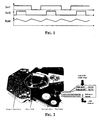
- the drive signals that are conveyed to the VCM functioning in a PSM mode are shown in Figure 1.
- the PSM output power signals OUT1 and OUT2! are driven to a high logic level Vcc (where Vcc is power supply voltage) when PSM input signals are at high digital level and to a low logic level equal to the ground voltage when PSM input signals are at low digital level.
- Vcc power supply voltage
- a null output current is obtained by driving both OUT1 and OUT2! with a 50% duty cycle.
- the ripple on the output current, Iload is also shown.
- the PSM technique does not suffer, like the PWM technique, of the well known "Ton minimum" problem that does not allow a good control of the output voltage below a certain value of the duty cycle.
- the load current ripple decreases as the load current decreases toward zero and this is a benefit when there is the need to implement a very precise control under relatively low output current levels as is typically the case in HD drives.
- FIG. 2 is a photographic reproduction of a typical HD drive mechanical arrangement, showing the voice coil motor that moves the R/W head carrying arm and the flexible flat cable connection (Flex Cable) carrying the power signal lines (PSM OUT1 and PSM OUT2! as well as the low level signal lines (R/W head signals), running parallel in the flat cable.
- the voice coil motor that moves the R/W head carrying arm and the flexible flat cable connection (Flex Cable) carrying the power signal lines (PSM OUT1 and PSM OUT2! as well as the low level signal lines (R/W head signals), running parallel in the flat cable.
- both PSM drive signals approach the 50% duty cycle and therefore the PSM commutations become so close to each other that may practically be considered concurrent.
- switching energies sum and reach a level that may be sufficient to inject switching noise from the VCM power lines in adjacent low level signals lines of the flexible flat cable of electrical connection of the moving arm.
- Figures 3 and 4 show simulation waveforms when the commutations of the two PSM drive signals are not concurrent and concurrent, respectively.
- the noise due to the two commutations concentrates in a narrowing temporal zone and the resulting energy level increases to a point sufficient to inject noise into adjacent low level signals lines of the flexible cable, corrupting data being transferred through the R/W channel.
- the purpose of the present invention is to overcome the above discussed criticalness of a PSM driver of a voice coil motor of an arm carrying a transducer that require a precise positioning actuated by the voice coil motor.
- degradation of the S/N ratio of low level signal lines of data transfer from and to the transducer, due to injection of switching noise from nearby power signal lines conveying PSM drive signals to the motor coil is effectively prevented by enhancing the time offset between commutation edges of the two PSM drive signals either by phase shifting one of the signals from the other signal by a programmed amount sufficient to prevent any concurrent or quasi concurrent commutation of both signals or by broadening the width of the pulses of one PSM drive signal and narrowing the width of the pulses of the other PSM drive signal while maintaining constant the duty-cycle of each of the two drive signals.
- these programmed modifying interventions on the PSM drive signals are disabled when a command or input data, for programming the output current level to be forced through the PSM driven motor coil, surpasses a certain threshold level or the duty cycle of the single PSM drive signals surpasses a certain threshold value in approaching the 50% value that corresponds to the condition of practically null output current delivered to the motor coil.
- the attendant increase of the ripple on the output current is eliminated when the driving conditions are such as to shift naturally apart the edges of the pulses of the pair of PSM drive signals, i.e. when the motor coil is driven at relatively high current levels.
- phase shifting of one PSM drive signal from the other by a pre-established amount can be implemented by delaying one of the would-be-complementary triangular reference waveforms with which the incoming control data is normally compared, over a certain number of bits that depends on the frequency of the system clock, in order to generate the two PSM drive signals.
- the duty-cycle of the single drive signals is maintained constant by coordinately modifying the two PSM drive signals, in practice subtracting an equivalent area to each broadened pulse of one of the two PSM drive signals and adding between the narrowed pulses of the other PSM drive signal a short "make-up" pulse of area equivalent to the area subtracted to the narrowed pulse.
- FIG. 5 shows a basic circuit diagram of PSM driving of a voice coil motor (VCM) through a full bridge output stage composed by the four MOSFET transistors MOS1, MOS2, MOS3, MOS4, connected between the supply node Vm and ground, controlled by the pair of PSM drive signals NEWOUT1 and NEWOUT2!.
- VCM voice coil motor
- the original command or input data is represented by a certain value or level ORIGINAL DATA that is fed through the digital n-bit input to the DATA INPUT MODULATION block of the circuit diagram of Figure 7 over a certain number of cycles that depends from the frequency of the system clock CLK, used for generating the pair of PSM drive signal by comparing the input value with two triangular reference signals synchronous with the system CLK and commonly in phase opposition to each other, namely TRIA_0 and TRIA_180.
- the command ORIGINAL DATA is modified.
- the original data is modulated at the input to produce a modified input signal MODIFIED DATA of constant energy content i.e. same area under the waveform of the now periodic signal.
- the pair of PSM drive signals are generated by comparing the input signal that according to this embodiment of the invention is the modified input signal MODIFIED DATA, with two triangular reference signals in phase opposition with each other, namely TRIA_0 and TRIA_180.
- the PSM drive signal NEWOUT1 has its pulses broadened thus adding areas A and areas C in correspondence of the trailing and leading edges of the pulse.
- the area under the pulse profile is kept unchanged by subtracting the area B to the subtended area of the pulse, thus keeping unchanged the duty cycle of the periodic signal.
- the pulses of the other PSM drive signal NEWOUT2! are narrowed by subtraction of areas of D and F in correspondence of their leading and trailing edges.
- the duty-cycle of the periodic signal that is the area subtended under the positive pulses, is maintained constant by the addition of a make-up or supplementary positive pulse of area E between each narrowed pulse of the PSM drive signal.
- Figure 7 is a high level circuit diagram for generating the above described modified PSM drive signals NEWOUT1 and NEWOUT2! by commanding a certain shift amount, through the digital m-bit input to the DATA INPUT MODULATION block, of the edges of the pulses of the PSM signals according to the modification scheme of Figure 6. Any skilled reader will be immediately able to practice the invention, by defining appropriate circuital details of his choice of the INPUT DATA MODULATOR block of Figure 7, such to accomplish the illustrated modification of the original data.
- the amount of edge shift that is introduced according to this first embodiment and consequently the subtended area to be added or eliminated in the respective modified PSM drive signals NEWOUT1 and NEWOUT2!, is predetermined such to ensure that the sum of PSM commutations energies as they get closer and closer will remain safely below a critical level that would generate an unacceptable S/N noise in low signal data upon injection via flexible cable parasitic capacitances into low level signal data lines.
- the amount of edge shift should not be excessive in order to limit the attendant increase of the ripple on the output current delivered to the motor coil, keeping it in an acceptable range.
- the amount of edge shift to be introduced may preferably be made to depend not only from the programmed level (e.g. DC level) of the current delivered to the load (e.g. to the VCM) but also on whether the sign of the programmed output current inverts.
- the programmed level e.g. DC level
- the load e.g. to the VCM
- Figures 8, 9 and 10 clarify this aspect.
- a null or a positive output current of relatively small DC level that is a programmed duty cycle of the two PSM drive signals falling in an established small range centered on the 50% value, for example 50% ⁇ 5%
- the opposite edge shifts that are respectively introduced in one and in the other PSM drive signals will always tend to space apart the trailing and leading edge commutations of the two PSM drive signals.
- the edge shifts are introduced when the programmed duty-cycle of the two PSM drive signals (that is the programmed DC level of the output current) falls in a certain range in the neighbour of 50%, for example 50% ⁇ x% (for example: 50% ⁇ 5%).
- the actual amount of shift to be introduced may be established such that, in the most critical condition of possible programmed level of an output current of negative sign, the switching edges of the two PSM drive signals will remain sufficiently spaced temporarily from one another even in case of a negative output current.
- This may require to increase the amount of shift to be introduced from the minimum amount that is sufficient to enhance the time offset of the switching edges when controlling a positive output current, in order to prevent that, when controlling a negative output current, a certain minimum time offset of the switching edges will be preserved.
- prevention of concurrency or quasi concurrency of PSM commutations is ensured by introducing a certain phase shift of one of the two PSM drive signals from the other.
- the amount of phase shift that is introduced according to this alternative embodiment between the PSM drive signals NEWOUT1 and NEWOUT2!, is predetermined such to ensure that the sum of PSM commutations energies as they get closer will remain safely below a critical level that would generate an unacceptable S/N noise in low signal data upon injection via flexible cable parasitic capacitances into low level signal data lines.
- the amount of phase shift should not be excessive in order to limit the attendant increase of the ripple on the output current delivered to the motor coil.
- phase shifting circuit when driving a relatively strong output current through the motor coil the phase shifting circuit may be disabled because the PSM pulse edges become naturally spaced from each other.
- the attendant increase of the ripple on the output current is significantly larger than in the case of the first embodiment.
- This aspect makes this alternative embodiment of phase shifting the two PSM drive signals somewhat less preferable.
- Figure 11 shows the waveforms of unshifted PSM drive signals (not modified according to this invention) in a condition of control of the head positioning VCM whereat the edges of the pulses of the two PSM drive signals of the output bridge devices are relatively close to each other (i.e. a relatively small output current, equivalent to 10 mA, is being forced through the motor coil).
- a relatively small output current equivalent to 10 mA
- Figure 12 shows the waveforms of the two PSM drive signals modified according to this alternative embodiment of the invention based on the introduction of a certain phase shift of one drive signal from the other, sufficient to prevent concurrent or quasi concurrent PSM commutations. This effectively avoids injection of switching noise on low level signal lines and is accompanied by a sensible increase of the ripple on the output current.
- ripple amplitude appears to sensibly increase when implementing the phase shifting of the two PSM drive signals, in a measure much more pronounced than with the edge shifting technique of the first embodiment, it has been proven that such a large increase of the ripple amplitude on the output current is not significantly affecting the control performance of the voice coil motor, in view of the fact that the motor coil being driven is practically an LR circuit that by acting as a low pass filter on the motor current, has a strong filtering action on the current being driven therethrough and makes the motor sensible only to the mean or effective current value (DC level).
- phase shifting of one of the two PSM drive signals from the other can be implemented in a quite straightforward manner for example by delaying one of the two triangular reference signals (normally in phase opposition) TRIA _0 and TRIA_180, with which the input command ORIGINAL DATA is compared to generate the PSM drive signal pair, by an effective amount, just as needed to securely prevent switching noise injection phenomena.
- the delaying circuit introduced in the path of one of the two triangular reference signals will be bypassed when the programmed output DC current level ORIGINAL DATA surpasses a certain threshold.
- the threshold at which the edge or phase shift is introduced directly depends on the programmed DC level (ORIGINAL DATA), therefore, normally there is not any need of sensing the output current and the enabling or disabling of the shifting may be automatically determined by the level of the programmed DC current.
Landscapes
- Engineering & Computer Science (AREA)
- Power Engineering (AREA)
- Control Of Motors That Do Not Use Commutators (AREA)
- Control Of Linear Motors (AREA)
Priority Applications (3)
| Application Number | Priority Date | Filing Date | Title |
|---|---|---|---|
| EP06425391A EP1865505B1 (de) | 2006-06-09 | 2006-06-09 | Verhinderung von Störungen durch konkurierende Signale bei der Ansteuerung einer H-Brücke eines Schwingspulenmotors |
| DE602006016089T DE602006016089D1 (de) | 2006-06-09 | 2006-06-09 | Verhinderung von Störungen durch konkurierende Signale bei der Ansteuerung einer H-Brücke eines Schwingspulenmotors |
| US11/760,185 US8044619B2 (en) | 2006-06-09 | 2007-06-08 | Prevention of concurrent PWM or PSM commutations of power signals driving a voice coil motor (VCM) to reduce S/N ratio degradation of low level signal lines of a R/W head |
Applications Claiming Priority (1)
| Application Number | Priority Date | Filing Date | Title |
|---|---|---|---|
| EP06425391A EP1865505B1 (de) | 2006-06-09 | 2006-06-09 | Verhinderung von Störungen durch konkurierende Signale bei der Ansteuerung einer H-Brücke eines Schwingspulenmotors |
Publications (2)
| Publication Number | Publication Date |
|---|---|
| EP1865505A1 true EP1865505A1 (de) | 2007-12-12 |
| EP1865505B1 EP1865505B1 (de) | 2010-08-11 |
Family
ID=37236006
Family Applications (1)
| Application Number | Title | Priority Date | Filing Date |
|---|---|---|---|
| EP06425391A Not-in-force EP1865505B1 (de) | 2006-06-09 | 2006-06-09 | Verhinderung von Störungen durch konkurierende Signale bei der Ansteuerung einer H-Brücke eines Schwingspulenmotors |
Country Status (3)
| Country | Link |
|---|---|
| US (1) | US8044619B2 (de) |
| EP (1) | EP1865505B1 (de) |
| DE (1) | DE602006016089D1 (de) |
Cited By (1)
| Publication number | Priority date | Publication date | Assignee | Title |
|---|---|---|---|---|
| CN108712130A (zh) * | 2018-06-15 | 2018-10-26 | Tcl空调器(中山)有限公司 | 单电阻电流采样移项控制方法、装置、设备及存储介质 |
Families Citing this family (1)
| Publication number | Priority date | Publication date | Assignee | Title |
|---|---|---|---|---|
| US9998042B2 (en) | 2013-03-04 | 2018-06-12 | Seagate Technology Llc | Torque disturbance cancellation for a motor |
Citations (7)
| Publication number | Priority date | Publication date | Assignee | Title |
|---|---|---|---|---|
| US4523134A (en) * | 1984-05-08 | 1985-06-11 | Matsushita Electrical Industrial Co., Ltd. | Control system for DC motors |
| EP0660495A1 (de) * | 1993-12-23 | 1995-06-28 | Commissariat A L'energie Atomique | Steuerungssystem für mit Gleichstrom versorgte elektronische Leistungs-Betätigungselemente |
| US5450252A (en) | 1993-02-19 | 1995-09-12 | Kabushiki Kaisha Toshiba | Hard disk drive including moving means for moving a recording/reproducing head and having a noise canceler utilizing series-connected filters in parallel with the moving means |
| EP0760552A1 (de) * | 1995-08-31 | 1997-03-05 | STMicroelectronics S.r.l. | Verfahren und Schaltung zur pulsbreitenmodulierten Brückensteuerung und Plattenantrieb unter Verwendung derselben |
| EP1137162A1 (de) * | 2000-03-23 | 2001-09-26 | STMicroelectronics S.r.l. | Analogdigitale Pulsbreitenmodulatorsteuerschaltung |
| US20010054874A1 (en) | 2000-06-16 | 2001-12-27 | Nec Corporation | Spindle motor drive circuit |
| US6995537B1 (en) * | 2005-02-14 | 2006-02-07 | Texas Instruments Incorporated | Closed-loop control system to mitigate PWM switching noise |
-
2006
- 2006-06-09 EP EP06425391A patent/EP1865505B1/de not_active Not-in-force
- 2006-06-09 DE DE602006016089T patent/DE602006016089D1/de active Active
-
2007
- 2007-06-08 US US11/760,185 patent/US8044619B2/en not_active Expired - Fee Related
Patent Citations (7)
| Publication number | Priority date | Publication date | Assignee | Title |
|---|---|---|---|---|
| US4523134A (en) * | 1984-05-08 | 1985-06-11 | Matsushita Electrical Industrial Co., Ltd. | Control system for DC motors |
| US5450252A (en) | 1993-02-19 | 1995-09-12 | Kabushiki Kaisha Toshiba | Hard disk drive including moving means for moving a recording/reproducing head and having a noise canceler utilizing series-connected filters in parallel with the moving means |
| EP0660495A1 (de) * | 1993-12-23 | 1995-06-28 | Commissariat A L'energie Atomique | Steuerungssystem für mit Gleichstrom versorgte elektronische Leistungs-Betätigungselemente |
| EP0760552A1 (de) * | 1995-08-31 | 1997-03-05 | STMicroelectronics S.r.l. | Verfahren und Schaltung zur pulsbreitenmodulierten Brückensteuerung und Plattenantrieb unter Verwendung derselben |
| EP1137162A1 (de) * | 2000-03-23 | 2001-09-26 | STMicroelectronics S.r.l. | Analogdigitale Pulsbreitenmodulatorsteuerschaltung |
| US20010054874A1 (en) | 2000-06-16 | 2001-12-27 | Nec Corporation | Spindle motor drive circuit |
| US6995537B1 (en) * | 2005-02-14 | 2006-02-07 | Texas Instruments Incorporated | Closed-loop control system to mitigate PWM switching noise |
Cited By (1)
| Publication number | Priority date | Publication date | Assignee | Title |
|---|---|---|---|---|
| CN108712130A (zh) * | 2018-06-15 | 2018-10-26 | Tcl空调器(中山)有限公司 | 单电阻电流采样移项控制方法、装置、设备及存储介质 |
Also Published As
| Publication number | Publication date |
|---|---|
| US8044619B2 (en) | 2011-10-25 |
| US20070296362A1 (en) | 2007-12-27 |
| EP1865505B1 (de) | 2010-08-11 |
| DE602006016089D1 (de) | 2010-09-23 |
Similar Documents
| Publication | Publication Date | Title |
|---|---|---|
| US6804131B2 (en) | PWM/linear driver for an electromagnetic load | |
| US5869946A (en) | PWM control of motor driver | |
| US7002307B2 (en) | Single phase motor unit, method of driving single phase motor and integrated circuit | |
| US5977737A (en) | Digital motor driver circuit and method | |
| US7126781B1 (en) | Disk drive employing a multi-stage pulse width modulated voice coil motor driver | |
| JP5377579B2 (ja) | 高効率、バランスを保たれた出力増幅器システム | |
| JP4235561B2 (ja) | 半ブリッジ駆動回路とその駆動回路を備える電力変換システム | |
| US8093847B2 (en) | Motor drive circuit, method, and disc device using the same | |
| US20020158600A1 (en) | Brushless-motor driver in PWM mode | |
| US7884583B2 (en) | Speed recognition for half bridge control | |
| US9503011B2 (en) | Motor driving method, motor driving device, and hard disk device | |
| CN100405716C (zh) | 功率变换装置 | |
| US7622873B2 (en) | Motor drive device and drive method | |
| US5077540A (en) | Minimum pulse width switching power amplifier | |
| US11037596B2 (en) | Motor driver device and semiconductor device | |
| US7449854B2 (en) | PWM signal generation apparatus and method thereof and motor control apparatus and method thereof | |
| EP1865505B1 (de) | Verhinderung von Störungen durch konkurierende Signale bei der Ansteuerung einer H-Brücke eines Schwingspulenmotors | |
| US8207695B2 (en) | Control circuit of a full-bridge stage | |
| US7542262B2 (en) | Apparatus for driving an electromagnetic load | |
| JP2009529848A (ja) | Pmモータのための、切替ノードをベースとするセンサレスモータ制御 | |
| US6535035B2 (en) | Driver and method for switching applications | |
| US20040264948A1 (en) | Driving circuit for switches of direct current fan motor | |
| EP2237405B1 (de) | Steuervorrichtung zum Wechseln der Antriebsmodalität einer elektromagnetischen Last | |
| US10734929B2 (en) | Device and method for symmetric load switching in an H bridge | |
| JP7169816B2 (ja) | モータドライバ装置及び半導体装置 |
Legal Events
| Date | Code | Title | Description |
|---|---|---|---|
| PUAI | Public reference made under article 153(3) epc to a published international application that has entered the european phase |
Free format text: ORIGINAL CODE: 0009012 |
|
| AK | Designated contracting states |
Kind code of ref document: A1 Designated state(s): AT BE BG CH CY CZ DE DK EE ES FI FR GB GR HU IE IS IT LI LT LU LV MC NL PL PT RO SE SI SK TR |
|
| AX | Request for extension of the european patent |
Extension state: AL BA HR MK YU |
|
| 17P | Request for examination filed |
Effective date: 20080603 |
|
| 17Q | First examination report despatched |
Effective date: 20080703 |
|
| AKX | Designation fees paid |
Designated state(s): DE FR GB IT |
|
| GRAP | Despatch of communication of intention to grant a patent |
Free format text: ORIGINAL CODE: EPIDOSNIGR1 |
|
| RAP1 | Party data changed (applicant data changed or rights of an application transferred) |
Owner name: STMICROELECTRONICS SRL |
|
| GRAS | Grant fee paid |
Free format text: ORIGINAL CODE: EPIDOSNIGR3 |
|
| GRAA | (expected) grant |
Free format text: ORIGINAL CODE: 0009210 |
|
| AK | Designated contracting states |
Kind code of ref document: B1 Designated state(s): DE FR GB IT |
|
| REG | Reference to a national code |
Ref country code: GB Ref legal event code: FG4D |
|
| REF | Corresponds to: |
Ref document number: 602006016089 Country of ref document: DE Date of ref document: 20100923 Kind code of ref document: P |
|
| PG25 | Lapsed in a contracting state [announced via postgrant information from national office to epo] |
Ref country code: IT Free format text: LAPSE BECAUSE OF FAILURE TO SUBMIT A TRANSLATION OF THE DESCRIPTION OR TO PAY THE FEE WITHIN THE PRESCRIBED TIME-LIMIT Effective date: 20100811 |
|
| PLBE | No opposition filed within time limit |
Free format text: ORIGINAL CODE: 0009261 |
|
| STAA | Information on the status of an ep patent application or granted ep patent |
Free format text: STATUS: NO OPPOSITION FILED WITHIN TIME LIMIT |
|
| 26N | No opposition filed |
Effective date: 20110512 |
|
| REG | Reference to a national code |
Ref country code: DE Ref legal event code: R097 Ref document number: 602006016089 Country of ref document: DE Effective date: 20110512 |
|
| PGFP | Annual fee paid to national office [announced via postgrant information from national office to epo] |
Ref country code: FR Payment date: 20111221 Year of fee payment: 6 |
|
| GBPC | Gb: european patent ceased through non-payment of renewal fee |
Effective date: 20120609 |
|
| REG | Reference to a national code |
Ref country code: FR Ref legal event code: ST Effective date: 20130228 |
|
| REG | Reference to a national code |
Ref country code: DE Ref legal event code: R119 Ref document number: 602006016089 Country of ref document: DE Effective date: 20130101 |
|
| PG25 | Lapsed in a contracting state [announced via postgrant information from national office to epo] |
Ref country code: FR Free format text: LAPSE BECAUSE OF NON-PAYMENT OF DUE FEES Effective date: 20120702 Ref country code: DE Free format text: LAPSE BECAUSE OF NON-PAYMENT OF DUE FEES Effective date: 20130101 Ref country code: GB Free format text: LAPSE BECAUSE OF NON-PAYMENT OF DUE FEES Effective date: 20120609 |