EP1865518A2 - Joule heating apparatus for curing powder coated generator rotor coils - Google Patents
Joule heating apparatus for curing powder coated generator rotor coils Download PDFInfo
- Publication number
- EP1865518A2 EP1865518A2 EP07109887A EP07109887A EP1865518A2 EP 1865518 A2 EP1865518 A2 EP 1865518A2 EP 07109887 A EP07109887 A EP 07109887A EP 07109887 A EP07109887 A EP 07109887A EP 1865518 A2 EP1865518 A2 EP 1865518A2
- Authority
- EP
- European Patent Office
- Prior art keywords
- coils
- metal conductor
- temperature
- transformer
- current
- Prior art date
- Legal status (The legal status is an assumption and is not a legal conclusion. Google has not performed a legal analysis and makes no representation as to the accuracy of the status listed.)
- Withdrawn
Links
- 239000000843 powder Substances 0.000 title claims description 18
- 238000010438 heat treatment Methods 0.000 title description 17
- 238000000576 coating method Methods 0.000 claims abstract description 17
- 238000000034 method Methods 0.000 claims abstract description 17
- 239000011248 coating agent Substances 0.000 claims abstract description 16
- 239000002184 metal Substances 0.000 claims abstract description 16
- 229910052751 metal Inorganic materials 0.000 claims abstract description 16
- 239000004020 conductor Substances 0.000 claims abstract description 15
- 238000004804 winding Methods 0.000 claims description 30
- 238000012544 monitoring process Methods 0.000 claims 1
- 239000000463 material Substances 0.000 description 6
- 230000005855 radiation Effects 0.000 description 6
- 229910000881 Cu alloy Inorganic materials 0.000 description 4
- 239000004593 Epoxy Substances 0.000 description 4
- 239000011810 insulating material Substances 0.000 description 3
- 230000008878 coupling Effects 0.000 description 2
- 238000010168 coupling process Methods 0.000 description 2
- 238000005859 coupling reaction Methods 0.000 description 2
- 230000005684 electric field Effects 0.000 description 2
- 238000004924 electrostatic deposition Methods 0.000 description 2
- 238000009413 insulation Methods 0.000 description 2
- 238000004519 manufacturing process Methods 0.000 description 2
- 238000003860 storage Methods 0.000 description 2
- 229920001187 thermosetting polymer Polymers 0.000 description 2
- RYGMFSIKBFXOCR-UHFFFAOYSA-N Copper Chemical compound [Cu] RYGMFSIKBFXOCR-UHFFFAOYSA-N 0.000 description 1
- 230000033228 biological regulation Effects 0.000 description 1
- 238000010276 construction Methods 0.000 description 1
- 238000007796 conventional method Methods 0.000 description 1
- 229910052802 copper Inorganic materials 0.000 description 1
- 239000010949 copper Substances 0.000 description 1
- 230000001419 dependent effect Effects 0.000 description 1
- 238000000151 deposition Methods 0.000 description 1
- 230000008021 deposition Effects 0.000 description 1
- 238000013461 design Methods 0.000 description 1
- 238000010586 diagram Methods 0.000 description 1
- 238000011156 evaluation Methods 0.000 description 1
- 238000005338 heat storage Methods 0.000 description 1
- 230000006698 induction Effects 0.000 description 1
- 238000012986 modification Methods 0.000 description 1
- 230000004048 modification Effects 0.000 description 1
- 239000011347 resin Substances 0.000 description 1
- 229920005989 resin Polymers 0.000 description 1
- 229910052709 silver Inorganic materials 0.000 description 1
- 239000004332 silver Substances 0.000 description 1
- 238000012546 transfer Methods 0.000 description 1
Images
Classifications
-
- H—ELECTRICITY
- H02—GENERATION; CONVERSION OR DISTRIBUTION OF ELECTRIC POWER
- H02K—DYNAMO-ELECTRIC MACHINES
- H02K15/00—Processes or apparatus specially adapted for manufacturing, assembling, maintaining or repairing of dynamo-electric machines
- H02K15/12—Impregnating, moulding insulation, heating or drying of windings, stators, rotors or machines
-
- H—ELECTRICITY
- H01—ELECTRIC ELEMENTS
- H01F—MAGNETS; INDUCTANCES; TRANSFORMERS; SELECTION OF MATERIALS FOR THEIR MAGNETIC PROPERTIES
- H01F41/00—Apparatus or processes specially adapted for manufacturing or assembling magnets, inductances or transformers; Apparatus or processes specially adapted for manufacturing materials characterised by their magnetic properties
- H01F41/02—Apparatus or processes specially adapted for manufacturing or assembling magnets, inductances or transformers; Apparatus or processes specially adapted for manufacturing materials characterised by their magnetic properties for manufacturing cores, coils, or magnets
- H01F41/04—Apparatus or processes specially adapted for manufacturing or assembling magnets, inductances or transformers; Apparatus or processes specially adapted for manufacturing materials characterised by their magnetic properties for manufacturing cores, coils, or magnets for manufacturing coils
- H01F41/12—Insulating of windings
- H01F41/122—Insulating between turns or between winding layers
-
- H—ELECTRICITY
- H01—ELECTRIC ELEMENTS
- H01F—MAGNETS; INDUCTANCES; TRANSFORMERS; SELECTION OF MATERIALS FOR THEIR MAGNETIC PROPERTIES
- H01F5/00—Coils
- H01F5/06—Insulation of windings
Definitions
- This invention relates to the manufacture of generator electromagnetic rotors, and specifically, to curing powder-coated generator coils by means of joule heating.
- Electrostatic deposition of epoxy powders is an alternative to existing taping techniques used for insulating rotor coils in generators.
- Various commercial thermosetting materials are available for powder coating, and all require curing at elevated temperatures in the range of 120C to 200C. These materials have been shown to have suitable mechanical and electrical properties for use as insulation, and various alternate heating methods for curing the coatings have been proposed.
- Field coils for electromagnetic rotors that comprise multiple windings substantially entirely coated with a powder resin are disclosed in commonly owned U.S. Patent No. 6,686,822 .
- the powder coating is typically applied by means of electrostatic deposition of a dielectric insulating material onto the generator coils as an alternative to more costly and conventional techniques such as the manual application of insulating materials via manual tape winding. While powder coating has been advantageous as a replacement insulation, the drawback has been the curing process following deposition.
- the coated coils are transferred to a commercial convection oven that may be as long as thirty feet. As might be expected, such ovens are not easily transported and are expensive to build and maintain.
- the present invention relates to a method and apparatus suitable for curing a powder-coated metal bar by means of Joule (also known as resistance) heating.
- the metal bar may be a copper alloy generator coil and the coating may be an electrostatically applied epoxy or blended powder coating.
- the invention here enables low cost curing of the powder coat insulating materials by avoiding the high capital cost of a convection oven.
- the apparatus employs a power transformer in a special configuration where the workpiece (for example, the rotor generator coil) is configured in a series loop to form a single turn secondary winding of the power transformer.
- the primary winding of the power transformer is energized with AC current (preferably 50 or 60 hz due to standards of line voltage supplies), and creates a magnetic field in the transformer core.
- the secondary winding is formed as at least one winding around the core.
- Two or more rotor generator coils are electrically connected in a series loop by a clamping device in the configuration such that resulting ends of the loop can then be electrically connected to each end of the power transformer secondary winding. The connection may be made by means of a clamping device.
- the magnetic field thus creates an electric field in the secondary winding, and a resulting current is created in the series loop formed by the rotor generator coils.
- the temperature of the rotor coil(s) is monitored while the power transformer primary coil is energized and used as part of a feedback loop to regulate the temperature.
- the present invention relates to a method of curing a coating on a metal conductor comprising: (a) connecting the metal conductor to the output of a power transformer; and (b) passing a current through the metal conductor so as to achieve a surface temperature sufficient to cure the coating.
- the present invention relates to a method of curing a powder coating on at least a pair of coils of a generator rotor comprising: (a) configuring a step-down transformer to include a primary winding with plural windings around a core, and a secondary winding with at least one winding around the core, but fewer than the primary winding; (b) connecting two or more generator coils in a series loop and electrically connecting the ends of the loop to the secondary winding via a connecting element having the same resistance and heat loss as the generator coils; (c) using the transformer to produce a current through said one or more coils to thereby heat the one or more coils to a desired curing temperature.
- Joule or resistance heating is achieved by the dissipation associated with internal resistance and the corresponding voltage drop when a DC or AC current flows through the workpiece. This phenomena is well understood, and of course is the basis for many types of electrical heating elements. For application to a rotor coil, consideration must be given to the materials and construction and resulting extremely low resistance of the workpiece, and the resulting large current that is likely to be required. The amount of current will depend on the heat capacity of the workpiece and heat loss due to convection and radiation from the workpiece, and the required curing temperature.
- the equations for heat gain and loss during Joule heating of an object are set forth below.
- the source of heating is Joule heating Qj
- the heating load comprises losses from convection Qc and radiation Qr from the surface and heat storage Qs associated with the heat capacity of the workpiece.
- the heat capacity can be readily calculated, but the convection and radiation loads are strongly dependent on geometry and materials properties. In this case, with a reactive exothermic thermosetting material on the surface of the workpiece, it is critical to verify experimentally the heat loss.
- the following four equations show the dependence of each component of heat loss or gain.
- R denotes resistance
- h denotes the heat transfer coefficient
- a s is the cross-sectional area
- vol is the volume
- T ⁇ is the surrounding temperature
- T is the part temperature
- ⁇ m is the mass density
- C p is the heat capacity
- ⁇ is Boltzmann's constant.
- the resistance is a critical factor in calculating the Joule heating.
- the nominal resistance R 0 depends on geometry and material properties where L is length, A s is cross-sectional area and ⁇ R is the resistivity at nominal temperature T 0 .
- a voltage source 10 is used to supply power to a power transformer 12.
- the source 10 may provide, for example, 440V or 220V to the transformer.
- First and second powder-coated coil elements 14, 16 of a generator rotor coil are connected in series via a clamping device 18 that forms part of the single-turn secondary winding 20 about the core of the transformer 12 via coupling 22.
- the rest of the secondary winding that extends from coupling 22 and around the core is a permanent part of the power transformer.
- the secondary winding extending about the transformer core can be designed to have the same heat loss and resistance per unit length as the rotor coil itself, so that no temperature differential along the length of the secondary coil occurs.
- the power transformer is a high-current transformer that reduces voltage to produce high current in the powder-coated elements 14, 16.
- the elements 14, 16 are copper-alloy generator coils with an electrostatically-applied epoxy or blended epoxy powder coating.
- the primary winding (not shown) of the transformer 12 is energized with AC current (preferably 50 or 60 Hz), creating a magnetic field in the transformer core (also not shown).
- the magnetic field creates an electric field in the secondary winding 20, and a resulting current i is generated in the series loop formed by the rotor coils.
- the predetermined required current is sufficient to heat the coil elements 14, 16 to the temperature necessary to cure the powder coating, for example, 150C.
- the temperature of the rotor coil elements 14, 16 is monitored while the primary coil is energized, and used as an input to an otherwise conventional proportional-integral-derivative feedback control loop for continual regulation of the temperature.
- the temperature can be measured directly and the voltage adjusted as necessary to vary the current to produce the desired temperature.
- the temperature can be inferred from the voltage and current characteristics, since resistance in the coil elements is temperature dependant.
Landscapes
- Engineering & Computer Science (AREA)
- Manufacturing & Machinery (AREA)
- Power Engineering (AREA)
- Manufacture Of Motors, Generators (AREA)
Abstract
A method of curing a coating on a metal conductor (14) comprising: (a) connecting the metal conductor in series with a power transformer (12); and (b) passing a current through the metal conductor so as to achieve a temperature sufficient to cure the coating.
Description
- This invention relates to the manufacture of generator electromagnetic rotors, and specifically, to curing powder-coated generator coils by means of joule heating.
- Electrostatic deposition of epoxy powders is an alternative to existing taping techniques used for insulating rotor coils in generators. Various commercial thermosetting materials are available for powder coating, and all require curing at elevated temperatures in the range of 120C to 200C. These materials have been shown to have suitable mechanical and electrical properties for use as insulation, and various alternate heating methods for curing the coatings have been proposed.
- Convection, induction, radiation and Joule heating have found application in various other industrial processes, and are sometimes used in combination with each other. Many factors must be considered, however, in selecting a system that can achieve a uniform and repeatable curing profile for a specific application.
- Field coils for electromagnetic rotors that comprise multiple windings substantially entirely coated with a powder resin are disclosed in commonly owned
U.S. Patent No. 6,686,822 . The powder coating is typically applied by means of electrostatic deposition of a dielectric insulating material onto the generator coils as an alternative to more costly and conventional techniques such as the manual application of insulating materials via manual tape winding. While powder coating has been advantageous as a replacement insulation, the drawback has been the curing process following deposition. Typically, the coated coils are transferred to a commercial convection oven that may be as long as thirty feet. As might be expected, such ovens are not easily transported and are expensive to build and maintain. - Accordingly, there remains a need for a simplified, less costly, but effective curing means for large powder-coated components such as copper alloy generator coils.
- The present invention relates to a method and apparatus suitable for curing a powder-coated metal bar by means of Joule (also known as resistance) heating. As already indicated, the metal bar may be a copper alloy generator coil and the coating may be an electrostatically applied epoxy or blended powder coating. The invention here enables low cost curing of the powder coat insulating materials by avoiding the high capital cost of a convection oven. More specifically, the apparatus employs a power transformer in a special configuration where the workpiece (for example, the rotor generator coil) is configured in a series loop to form a single turn secondary winding of the power transformer. The primary winding of the power transformer is energized with AC current (preferably 50 or 60 hz due to standards of line voltage supplies), and creates a magnetic field in the transformer core. The secondary winding is formed as at least one winding around the core. Two or more rotor generator coils are electrically connected in a series loop by a clamping device in the configuration such that resulting ends of the loop can then be electrically connected to each end of the power transformer secondary winding. The connection may be made by means of a clamping device. The magnetic field thus creates an electric field in the secondary winding, and a resulting current is created in the series loop formed by the rotor generator coils. The temperature of the rotor coil(s) is monitored while the power transformer primary coil is energized and used as part of a feedback loop to regulate the temperature.
- Accordingly, in one aspect, the present invention relates to a method of curing a coating on a metal conductor comprising: (a) connecting the metal conductor to the output of a power transformer; and (b) passing a current through the metal conductor so as to achieve a surface temperature sufficient to cure the coating.
- In another aspect, the present invention relates to a method of curing a powder coating on at least a pair of coils of a generator rotor comprising: (a) configuring a step-down transformer to include a primary winding with plural windings around a core, and a secondary winding with at least one winding around the core, but fewer than the primary winding; (b) connecting two or more generator coils in a series loop and electrically connecting the ends of the loop to the secondary winding via a connecting element having the same resistance and heat loss as the generator coils; (c) using the transformer to produce a current through said one or more coils to thereby heat the one or more coils to a desired curing temperature.
- The invention will now be described in detail in connection with the drawing identified below.
- Embodiments of the present invention will now be described, by way of example only, with reference to the accompanying drawings, in which:
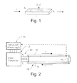
- Figure 1 illustrates part of a coil with labels indicating symbols representing variables in the basic equations for heat gain and loss during Joule heating; and
- Figure 2 is a schematic diagram of a Joule heating apparatus in accordance with an exemplary embodiment of the invention.
- Joule or resistance heating is achieved by the dissipation associated with internal resistance and the corresponding voltage drop when a DC or AC current flows through the workpiece. This phenomena is well understood, and of course is the basis for many types of electrical heating elements. For application to a rotor coil, consideration must be given to the materials and construction and resulting extremely low resistance of the workpiece, and the resulting large current that is likely to be required. The amount of current will depend on the heat capacity of the workpiece and heat loss due to convection and radiation from the workpiece, and the required curing temperature. For a particular embodiment of interest, with an overall coil length of about 30 feet and a cross section of approximately 1 inch by ¼ inch, initial evaluations indicated that heat loads are on the order of 3000W per coil in the steady state heating condition, and that a corresponding current on the order of 800 amps would be required. This is the basic information that is required to design a transformer suitable for this application. A critical aspect of the system is to make good electrical contact between the coils and the transformer. Further, the secondary winding of the transformer must be kept within acceptable temperature limits.
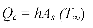
- In connection with Figure 1, the equations for heat gain and loss during Joule heating of an object are set forth below. The source of heating is Joule heating Qj, and the heating load comprises losses from convection Qc and radiation Qr from the surface and heat storage Qs associated with the heat capacity of the workpiece. The heat capacity can be readily calculated, but the convection and radiation loads are strongly dependent on geometry and materials properties. In this case, with a reactive exothermic thermosetting material on the surface of the workpiece, it is critical to verify experimentally the heat loss. The following four equations show the dependence of each component of heat loss or gain. Current is denoted as i, R denotes resistance, h denotes the heat transfer coefficient, A s is the cross-sectional area, vol is the volume, T∞ is the surrounding temperature, T is the part temperature, ρm is the mass density, C p is the heat capacity, and σ is Boltzmann's constant.
- Joule Heating :

- Convection :
- Radiation :

- Storage :

- Joule Heating :

- Convection :

- Radiation :

- Storage :

- The resistance is a critical factor in calculating the Joule heating. The nominal resistance R 0 depends on geometry and material properties where L is length, As is cross-sectional area and ρR is the resistivity at nominal temperature T0.
- The actual resistance R 0 varies with temperature T with proportionality α which is the thermal coefficient of expansion. Power P depends on the resistance R and the current i as follows:


- An approximation of the values for temperature coefficient of resistance can be used by assuming the values for pure copper, whereas in fact the coils are made using a copper alloy containing a small amount of silver. The other relevant constants used in the subsequent calculations are tabulated below:


- Using the relationships expressed above, one can determine the resistance in a winding of a given size and configuration, and also determine the voltage necessary to produce a current that will raise the temperature of the winding sufficiently to cure the powder coating.
- With reference now to Figure 2, a
voltage source 10 is used to supply power to apower transformer 12. Thesource 10 may provide, for example, 440V or 220V to the transformer. First and second powder-coatedcoil elements clamping device 18 that forms part of the single-turnsecondary winding 20 about the core of thetransformer 12 viacoupling 22. The rest of the secondary winding that extends from coupling 22 and around the core (not shown) is a permanent part of the power transformer. In order to provide best temperature uniformity, the secondary winding extending about the transformer core can be designed to have the same heat loss and resistance per unit length as the rotor coil itself, so that no temperature differential along the length of the secondary coil occurs. The power transformer is a high-current transformer that reduces voltage to produce high current in the powder-coatedelements elements - The primary winding (not shown) of the
transformer 12 is energized with AC current (preferably 50 or 60 Hz), creating a magnetic field in the transformer core (also not shown). The magnetic field creates an electric field in the secondary winding 20, and a resulting current i is generated in the series loop formed by the rotor coils. The predetermined required current is sufficient to heat thecoil elements - Preferably, the temperature of the
rotor coil elements - While the invention has been described in connection with what is presently considered to be the most practical and preferred embodiment, it is to be understood that the invention is not to be limited to the disclosed embodiment, but on the contrary, is intended to cover various modifications and equivalent arrangements included within the spirit and scope of the appended claims.
Claims (10)
- A method of curing a coating on a metal conductor (14) comprising:(a) connecting the metal conductor in series with a power transformer (12); and(b) passing a current through the metal conductor (14) so as to achieve a temperature sufficient to cure the coating.
- The method of claim 1 wherein the metal conductor comprises one or more generator coils (14, 16).
- The method of claim 1 further comprising:(c) establishing a feedback loop to adjust the temperature of the metal conductor (14) by varying the voltage input to the transformer (12) based on actual temperature of the metal conductor.
- The method of claim 1 wherein the power transformer (12) is a step-down transformer.
- The method of claim 1 wherein in step (a), the metal conductor (14) is series connected with a secondary winding (20) of the power transformer.
- The method of claim 2 wherein in step (a), a pair of coils (14, 16) are connected in series.
- The method of claim 5 wherein said conductor (14) and said secondary winding (20) have the same heat loss and resistance per unit length as the metal conductor.
- A method of curing a powder coating on at least a pair of coils (14, 16) of a generator rotor comprising:(a) configuring a step-down transformer (12) to include a primary winding with plural windings around a core, and a secondary winding (20) with at least one winding around the core, but fewer than said primary winding;(b) connecting two or more generator coils (14, 16) in a series loop and electrically connecting the ends of the loop to the secondary winding (20) via a connecting element (22) having the same resistance and heat loss as the generator coils.(c) using the transformer (12) to produce a current through said one or more coils to thereby heat said one or more coils to a desired curing temperature.
- The method of claim 8, further comprising:(a) monitoring the temperature of the one or more coils (14, 16) and varying a voltage input to the power transformer (12) to adjust the current as necessary to achieve the desired curing temperature.
- The method of claim 9 wherein the voltage input is initially 440V.
Applications Claiming Priority (1)
| Application Number | Priority Date | Filing Date | Title |
|---|---|---|---|
| US11/449,752 US20070285198A1 (en) | 2006-06-09 | 2006-06-09 | Joule heating apparatus for curing powder coated generator rotor coils |
Publications (1)
| Publication Number | Publication Date |
|---|---|
| EP1865518A2 true EP1865518A2 (en) | 2007-12-12 |
Family
ID=38480597
Family Applications (1)
| Application Number | Title | Priority Date | Filing Date |
|---|---|---|---|
| EP07109887A Withdrawn EP1865518A2 (en) | 2006-06-09 | 2007-06-08 | Joule heating apparatus for curing powder coated generator rotor coils |
Country Status (4)
| Country | Link |
|---|---|
| US (1) | US20070285198A1 (en) |
| EP (1) | EP1865518A2 (en) |
| JP (1) | JP2007330093A (en) |
| CN (1) | CN101087091A (en) |
Families Citing this family (3)
| Publication number | Priority date | Publication date | Assignee | Title |
|---|---|---|---|---|
| US9296039B2 (en) | 2012-04-24 | 2016-03-29 | United Technologies Corporation | Gas turbine engine airfoil impingement cooling |
| US9243502B2 (en) | 2012-04-24 | 2016-01-26 | United Technologies Corporation | Airfoil cooling enhancement and method of making the same |
| CN108355932B (en) * | 2016-01-08 | 2020-12-22 | 浙江黎盛新材料科技有限公司 | A metal plate coating curing device |
Family Cites Families (19)
| Publication number | Priority date | Publication date | Assignee | Title |
|---|---|---|---|---|
| US1163342A (en) * | 1909-03-17 | 1915-12-07 | Daniel Hurley | Method of drying and impregnating electrical conductors. |
| US2594096A (en) * | 1949-01-21 | 1952-04-22 | Westinghouse Electric Corp | Process for treating windings with completely-reactive compositions |
| US3145127A (en) * | 1961-06-28 | 1964-08-18 | Gen Electric | Method of insulating electrical components, such as small electric motors |
| US3527662A (en) * | 1969-10-01 | 1970-09-08 | Gen Electric | Impregnation of electrical coils using resistance heating and temperature sensing means |
| US3739132A (en) * | 1971-12-01 | 1973-06-12 | Interstate Drop Forge Co | Power control circuit for resistance heating moving conductors |
| US3904785A (en) * | 1974-01-11 | 1975-09-09 | Gen Electric | Method for insulating electric armature windings |
| US4407854A (en) * | 1981-03-24 | 1983-10-04 | Northern Telecom Limited | Manufacture of cable cores |
| US4596917A (en) * | 1984-01-16 | 1986-06-24 | General Electric Company | Resistance spot welder process monitor |
| US4725449A (en) * | 1985-05-22 | 1988-02-16 | The United States Of America As Represented By The United States Department Of Energy | Method of making radio frequency ion source antenna |
| IT1271941B (en) * | 1993-02-10 | 1997-06-10 | Cedal Srl | PROCEDURE FOR THE PRODUCTION OF PLASTIC LAMINATES WITH METALLIC LAMINS IN SPECIES FOR PRINTER CIRCUITS, WITH ENDOTHERMAL HEATING. |
| IT1272106B (en) * | 1993-03-18 | 1997-06-11 | Cedal Srl | SYSTEM FOR THE AUTOMATIC CONNECTION BETWEEN THE ELECTRICITY SOURCE AND THE STACKS OF PLASTIC LAMINATE PACKAGES, IN THE ENDOTHERMAL HEATING. |
| IT1264611B1 (en) * | 1993-06-15 | 1996-10-04 | Cedal Srl | PROCEDURE FOR THE PRODUCTION OF PLASTIC LAMINATES WITH ENDOTHERMAL HEATING, CONTINUOUS BELT AND CYCLIC MOLDING |
| DE4331086A1 (en) * | 1993-09-11 | 1995-03-16 | Herberts Gmbh | Process for the fixation of wound goods with radically polymerizable masses |
| JP2000297302A (en) * | 1999-02-12 | 2000-10-24 | Kubota Corp | Electric sintering method, electric sintering apparatus, and mold for electric sintering |
| DE19963491A1 (en) * | 1999-12-28 | 2001-07-05 | Alstom Power Schweiz Ag Baden | Process for producing high-quality insulation of electrical conductors or conductor bundles of rotating electrical machines by means of spray sintering |
| US6778053B1 (en) * | 2000-04-19 | 2004-08-17 | General Electric Company | Powder coated generator field coils and related method |
| US6632109B2 (en) * | 2001-06-28 | 2003-10-14 | General Electric Company | Powder coated terminal stud assemblies and methods of fabricating |
| DE102005017111B4 (en) * | 2005-04-13 | 2007-06-06 | Siemens Ag | Coating method for a winding head of an electrical machine |
| US7655271B2 (en) * | 2006-06-08 | 2010-02-02 | General Electric Company | Apparatus and method for masking |
-
2006
- 2006-06-09 US US11/449,752 patent/US20070285198A1/en not_active Abandoned
-
2007
- 2007-06-06 JP JP2007149909A patent/JP2007330093A/en not_active Withdrawn
- 2007-06-08 CN CNA2007101102695A patent/CN101087091A/en active Pending
- 2007-06-08 EP EP07109887A patent/EP1865518A2/en not_active Withdrawn
Also Published As
| Publication number | Publication date |
|---|---|
| JP2007330093A (en) | 2007-12-20 |
| CN101087091A (en) | 2007-12-12 |
| US20070285198A1 (en) | 2007-12-13 |
Similar Documents
| Publication | Publication Date | Title |
|---|---|---|
| Wrobel et al. | Contribution of end-winding proximity losses to temperature variation in electromagnetic devices | |
| Acero et al. | Simple resistance calculation in litz-wire planar windings for induction cooking appliances | |
| CN101360365B (en) | Method and device for object temperature control | |
| Lope et al. | Design and implementation of PCB inductors with litz-wire structure for conventional-size large-signal domestic induction heating applications | |
| US20040084443A1 (en) | Method and apparatus for induction heating of a wound core | |
| KR101123229B1 (en) | Method for manufacturing a transformer winding and method for curing adhesive on an insulating material in a transformer winding | |
| EP1865518A2 (en) | Joule heating apparatus for curing powder coated generator rotor coils | |
| Bruzzone et al. | Status report of the SULTAN test facility | |
| JP3754879B2 (en) | Superconducting cable analysis method | |
| Undeland et al. | A single-pass design method for high-frequency inductors | |
| Elmquist | Calculable coaxial resistors for precision measurements | |
| JP3698623B2 (en) | Superconducting cable | |
| Palacz et al. | Experimental analysis of the air-and water-based cooling solution for the three-phase line choke | |
| Skibinski et al. | Finite element prediction of losses and temperatures of laminated and composite inductors for AC drives | |
| US6909928B2 (en) | Method for manufacturing coils | |
| JP4261513B2 (en) | Superconducting cable | |
| De Coster et al. | Design of a foil-coiled inductor for the heating of steel wires | |
| Valeev et al. | Modeling Dependence of Active Power Loss in Plunger Core Arc Suppression Coils on Applied Voltage and Compensation Winding Current | |
| Kim et al. | Test result of the model coil for the conduction cooled HTS SMES | |
| Hewitt | Approaches to improving thermal performance of inductors with a view to improving power density | |
| Lazurenko et al. | Optimization of design parameters of autotransformers in ice melting scheme with non-inductive circuit on 6-10 kV overhead power lines | |
| JPS628148Y2 (en) | ||
| JP2006329925A (en) | Superconducting conductor evaluation method and apparatus | |
| O'Loughlin et al. | Optimization of adiabatic inverter transformers | |
| HK1114656B (en) | Arrangement for preparing pipelines |
Legal Events
| Date | Code | Title | Description |
|---|---|---|---|
| PUAI | Public reference made under article 153(3) epc to a published international application that has entered the european phase |
Free format text: ORIGINAL CODE: 0009012 |
|
| AK | Designated contracting states |
Kind code of ref document: A2 Designated state(s): AT BE BG CH CY CZ DE DK EE ES FI FR GB GR HU IE IS IT LI LT LU LV MC MT NL PL PT RO SE SI SK TR |
|
| AX | Request for extension of the european patent |
Extension state: AL BA HR MK YU |
|
| STAA | Information on the status of an ep patent application or granted ep patent |
Free format text: STATUS: THE APPLICATION IS DEEMED TO BE WITHDRAWN |
|
| 18D | Application deemed to be withdrawn |
Effective date: 20120103 |