EP1865596A1 - Induktionsmotorbetriebene Fadenliefergerät - Google Patents
Induktionsmotorbetriebene Fadenliefergerät Download PDFInfo
- Publication number
- EP1865596A1 EP1865596A1 EP06425379A EP06425379A EP1865596A1 EP 1865596 A1 EP1865596 A1 EP 1865596A1 EP 06425379 A EP06425379 A EP 06425379A EP 06425379 A EP06425379 A EP 06425379A EP 1865596 A1 EP1865596 A1 EP 1865596A1
- Authority
- EP
- European Patent Office
- Prior art keywords
- motor
- speed
- ref
- isq
- vector
- Prior art date
- Legal status (The legal status is an assumption and is not a legal conclusion. Google has not performed a legal analysis and makes no representation as to the accuracy of the status listed.)
- Withdrawn
Links
- 230000006698 induction Effects 0.000 title claims abstract description 16
- 230000004907 flux Effects 0.000 claims abstract description 29
- 238000004804 winding Methods 0.000 claims abstract description 9
- 230000001105 regulatory effect Effects 0.000 claims abstract 5
- 238000001514 detection method Methods 0.000 claims 1
- 239000004753 textile Substances 0.000 claims 1
- 230000001131 transforming effect Effects 0.000 claims 1
- 238000010586 diagram Methods 0.000 description 11
- 238000000034 method Methods 0.000 description 5
- 238000013459 approach Methods 0.000 description 4
- 230000001360 synchronised effect Effects 0.000 description 4
- 230000008901 benefit Effects 0.000 description 3
- 238000009941 weaving Methods 0.000 description 3
- 229910052779 Neodymium Inorganic materials 0.000 description 1
- 238000010521 absorption reaction Methods 0.000 description 1
- 238000004364 calculation method Methods 0.000 description 1
- 238000010276 construction Methods 0.000 description 1
- 238000012937 correction Methods 0.000 description 1
- 230000003247 decreasing effect Effects 0.000 description 1
- 238000013461 design Methods 0.000 description 1
- 238000011161 development Methods 0.000 description 1
- 230000004069 differentiation Effects 0.000 description 1
- 238000005516 engineering process Methods 0.000 description 1
- 230000005294 ferromagnetic effect Effects 0.000 description 1
- 238000002347 injection Methods 0.000 description 1
- 239000007924 injection Substances 0.000 description 1
- 238000009940 knitting Methods 0.000 description 1
- QEFYFXOXNSNQGX-UHFFFAOYSA-N neodymium atom Chemical compound [Nd] QEFYFXOXNSNQGX-UHFFFAOYSA-N 0.000 description 1
- 230000002093 peripheral effect Effects 0.000 description 1
- 230000008569 process Effects 0.000 description 1
- 239000004065 semiconductor Substances 0.000 description 1
- 230000009466 transformation Effects 0.000 description 1
- 238000000844 transformation Methods 0.000 description 1
- 230000007704 transition Effects 0.000 description 1
Images

Classifications
-
- D—TEXTILES; PAPER
- D03—WEAVING
- D03D—WOVEN FABRICS; METHODS OF WEAVING; LOOMS
- D03D47/00—Looms in which bulk supply of weft does not pass through shed, e.g. shuttleless looms, gripper shuttle looms, dummy shuttle looms
- D03D47/34—Handling the weft between bulk storage and weft-inserting means
- D03D47/36—Measuring and cutting the weft
-
- D—TEXTILES; PAPER
- D04—BRAIDING; LACE-MAKING; KNITTING; TRIMMINGS; NON-WOVEN FABRICS
- D04B—KNITTING
- D04B15/00—Details of, or auxiliary devices incorporated in, weft knitting machines, restricted to machines of this kind
- D04B15/38—Devices for supplying, feeding, or guiding threads to needles
- D04B15/48—Thread-feeding devices
- D04B15/482—Thread-feeding devices comprising a rotatable or stationary intermediate storage drum from which the thread is axially and intermittently pulled off; Devices which can be switched between positive feed and intermittent feed
- D04B15/486—Monitoring reserve quantity
-
- H—ELECTRICITY
- H02—GENERATION; CONVERSION OR DISTRIBUTION OF ELECTRIC POWER
- H02P—CONTROL OR REGULATION OF ELECTRIC MOTORS, ELECTRIC GENERATORS OR DYNAMO-ELECTRIC CONVERTERS; CONTROLLING TRANSFORMERS, REACTORS OR CHOKE COILS
- H02P21/00—Arrangements or methods for the control of electric machines by vector control, e.g. by control of field orientation
- H02P21/22—Current control, e.g. using a current control loop
-
- Y—GENERAL TAGGING OF NEW TECHNOLOGICAL DEVELOPMENTS; GENERAL TAGGING OF CROSS-SECTIONAL TECHNOLOGIES SPANNING OVER SEVERAL SECTIONS OF THE IPC; TECHNICAL SUBJECTS COVERED BY FORMER USPC CROSS-REFERENCE ART COLLECTIONS [XRACs] AND DIGESTS
- Y02—TECHNOLOGIES OR APPLICATIONS FOR MITIGATION OR ADAPTATION AGAINST CLIMATE CHANGE
- Y02P—CLIMATE CHANGE MITIGATION TECHNOLOGIES IN THE PRODUCTION OR PROCESSING OF GOODS
- Y02P70/00—Climate change mitigation technologies in the production process for final industrial or consumer products
- Y02P70/50—Manufacturing or production processes characterised by the final manufactured product
- Y02P70/62—Manufacturing or production processes characterised by the final manufactured product related technologies for production or treatment of textile or flexible materials or products thereof, including footwear
Definitions
- This invention relates to a yarn feeding device for weaving or knitting machines, and more particularly a yarn feeding device driven by an asynchronous induction motor.
- Yarn feeding devices in weaving machines are usually driven by synchronous, permanentmagnet brushless motors.
- One such yarn feeding device is disclosed in WO 03/029121 , in which the speed of the brushless motor driving the winding member of the device is vector controlled by a method which uses the rotor position information for sinusoidally controlling the motor. This is done because, as a person skilled in the art will appreciate, the torque in a PMSM, or Permanent Magnet Synchronous Motor, is controlled by injecting in the stator winding a triad of currents such that the resulting rotating stator field is at all times directed at 90° to the rotor flux vector.
- WO 03/029121 also discloses that the rotor position is detected by means of sensors or, alternatively, that the rotor position is obtained by indirectly measuring the stator's counter electromotive force (sensorless measuring).
- controlling the asynchronous induction motor has been traditionally regarded as being more complex and expensive than controlling the synchronous brushless motor. While this was substantially true until the recent past, today the development of digital electronic components (particularly DSP-based hybrid controllers) has drastically lowered the cost of this type of control, which in the past used to be regarded as too complex for the power of a microcontroller.
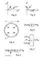
- a weft feeding device comprises a housing P in which an asynchronous induction motor M drives a coaxial flywheel V, integral with a yarn channel BR for delivering a yarn RT to be wound on a stationary storage drum TA.
- a weft supply sensor S detects whether a yarn reserve is available in a predetermined scanning area of the storage drum, and a yarn unwinding sensor Y delivers a pulse as each yarn loop unwinds from the storage drum.
- a processor unit CU receives the information from sensors S and Y, determines the speed required to maintain an appropriate yarn reserve on the drum, and generates a speed reference signal sp_ re f indicating the desired speed of flywheel V.
- the speed reference signal sp_ref from processor unit CU is applied to a subtractor 1, which compares it with a signal sp_meas indicating the actual current speed of the motor, and obtained by any of several known ways, some of which will be discussed below in the course of this disclosure.
- the result of the comparison is a speed error signal sp_err that is applied to a compensation block 2, which is a conventional calculating block known per se, and is typically either of the proportional-integral type (PI) or of the proportional-integral-derivative type (PID).
- Block 2 transforms sp_err into a correction output torque_ref, i.e. the torque that is required from the motor so that the motor speed error is neutralized.
- T ⁇ e n ⁇ p * I ⁇ s ⁇ q * ⁇
- Te the electromotive torque delivered by the motor
- np the number of pole pairs
- ⁇ the magnitude of the rotor flux
- Isq the magnitude of the current component at right angles to the rotor flux.
- the rotor flux ⁇ is normally adjusted to the highest feasible value that will not over-saturate the ferromagnetic circuit of the motor. Since the rotor flux is kept at a constant value, it follows that Isq is proportional to the desired torque. This circumstance is generally used in controlling brushless motors, particularly as the rotor flux, in this type of electric motor, is provided "freely" by the permanent magnets built into the rotor.
- the rotor flux of an induction motor is generated by the slip between the stator's rotating field and the rotor itself, and draws a flux-feeding current component Isd of current Is.
- the invention provides a way to reconstitute the rotor flux vector, based on the knowledge of the motor speed, i.e. sp_meas.
- the position and magnitude rot_flux of the rotor flux is computed in logic block 6, starting from the instantaneous currents read from the motor (Ia, Ib, Ic) and from the measured motor speed (sp_meas). To that purpose block 6 performs substantially the following steps:
- the speed of the motor may be measured by any of the following approaches, depending on the type of sensors available :
- control blocks may be integrated into a single control circuit, and more particularly they may be coded in a form that is executable by a microcontroller having an adequate computational power and provided with suitable peripherals, as obvious for a person skilled in the art, such as fast A/D converters with multiple sample-and-hold circuits, timers, PWM modulators, etc.
Landscapes
- Engineering & Computer Science (AREA)
- Textile Engineering (AREA)
- Power Engineering (AREA)
- Control Of Ac Motors In General (AREA)
Priority Applications (2)
| Application Number | Priority Date | Filing Date | Title |
|---|---|---|---|
| EP06425379A EP1865596A1 (de) | 2006-06-05 | 2006-06-05 | Induktionsmotorbetriebene Fadenliefergerät |
| CNA2007101096389A CN101085659A (zh) | 2006-06-05 | 2007-06-04 | 由感应电动机驱动的纱线馈送装置 |
Applications Claiming Priority (1)
| Application Number | Priority Date | Filing Date | Title |
|---|---|---|---|
| EP06425379A EP1865596A1 (de) | 2006-06-05 | 2006-06-05 | Induktionsmotorbetriebene Fadenliefergerät |
Publications (1)
| Publication Number | Publication Date |
|---|---|
| EP1865596A1 true EP1865596A1 (de) | 2007-12-12 |
Family
ID=37387344
Family Applications (1)
| Application Number | Title | Priority Date | Filing Date |
|---|---|---|---|
| EP06425379A Withdrawn EP1865596A1 (de) | 2006-06-05 | 2006-06-05 | Induktionsmotorbetriebene Fadenliefergerät |
Country Status (2)
| Country | Link |
|---|---|
| EP (1) | EP1865596A1 (de) |
| CN (1) | CN101085659A (de) |
Cited By (3)
| Publication number | Priority date | Publication date | Assignee | Title |
|---|---|---|---|---|
| CN103979349A (zh) * | 2014-04-21 | 2014-08-13 | 深圳市海浦蒙特科技有限公司 | 电机卷绕恒张力控制方法和系统 |
| CN106685297A (zh) * | 2016-12-12 | 2017-05-17 | 国网北京市电力公司 | 改进的异步电机模型参考自适应转速估计方法和装置 |
| KR102126946B1 (ko) * | 2020-02-10 | 2020-07-08 | 김모환 | 메탈릭사 급사장치 |
Families Citing this family (2)
| Publication number | Priority date | Publication date | Assignee | Title |
|---|---|---|---|---|
| EP2415916B1 (de) * | 2010-08-04 | 2015-03-04 | L.G.L. Electronics S.p.A. | Verfahren und Vorrichtung zur Erkennung unbeabsichtigten Anhaltens des Garns auf einer Fertigungsstrasse für Strickwaren |
| ITTO20120156A1 (it) * | 2012-02-22 | 2013-08-23 | Lgl Electronics Spa | Apparato di alimentazione di filato a tensione controllata per macchine tessili, con funzione di recupero del filato. |
Citations (6)
| Publication number | Priority date | Publication date | Assignee | Title |
|---|---|---|---|---|
| US5211207A (en) * | 1990-12-21 | 1993-05-18 | Ichikawa Iron Works Co., Ltd. | Weft feeder for weaving machine with angularly adjustable carrier |
| US5459386A (en) * | 1992-02-13 | 1995-10-17 | Mitsubishi Denki Kabushiki Kaisha | Motor drive control apparatus having a plurality of motor characteristics |
| EP1050610A2 (de) * | 1999-05-07 | 2000-11-08 | L.G.L. Electronics S.p.A. | Verfahren und Vorrichtung zur Steuerung von Rotationssignale des Fadenzuführungsrohr in Fadenliefervorrichtungen für Webmaschinen |
| EP1050611A2 (de) * | 1999-05-07 | 2000-11-08 | L.G.L. Electronics S.p.A. | Verfahren und Vorrichtung zur automatischen Regelung eines Asynchronmotors zum Antrieb des Fadenzuführungsrohrs in Liefervorrichtungen für Textilmaschinen |
| US6194856B1 (en) * | 1999-01-25 | 2001-02-27 | Hitachi, Ltd. | Motor driving apparatus including a modularized current control circuit and method of controlling the same |
| EP1523089A2 (de) * | 2003-10-07 | 2005-04-13 | Tsudakoma Kogyo Kabushiki Kaisha | System und Verfahren zur Ansteuerung eines Asynchronmotors |
-
2006
- 2006-06-05 EP EP06425379A patent/EP1865596A1/de not_active Withdrawn
-
2007
- 2007-06-04 CN CNA2007101096389A patent/CN101085659A/zh active Pending
Patent Citations (6)
| Publication number | Priority date | Publication date | Assignee | Title |
|---|---|---|---|---|
| US5211207A (en) * | 1990-12-21 | 1993-05-18 | Ichikawa Iron Works Co., Ltd. | Weft feeder for weaving machine with angularly adjustable carrier |
| US5459386A (en) * | 1992-02-13 | 1995-10-17 | Mitsubishi Denki Kabushiki Kaisha | Motor drive control apparatus having a plurality of motor characteristics |
| US6194856B1 (en) * | 1999-01-25 | 2001-02-27 | Hitachi, Ltd. | Motor driving apparatus including a modularized current control circuit and method of controlling the same |
| EP1050610A2 (de) * | 1999-05-07 | 2000-11-08 | L.G.L. Electronics S.p.A. | Verfahren und Vorrichtung zur Steuerung von Rotationssignale des Fadenzuführungsrohr in Fadenliefervorrichtungen für Webmaschinen |
| EP1050611A2 (de) * | 1999-05-07 | 2000-11-08 | L.G.L. Electronics S.p.A. | Verfahren und Vorrichtung zur automatischen Regelung eines Asynchronmotors zum Antrieb des Fadenzuführungsrohrs in Liefervorrichtungen für Textilmaschinen |
| EP1523089A2 (de) * | 2003-10-07 | 2005-04-13 | Tsudakoma Kogyo Kabushiki Kaisha | System und Verfahren zur Ansteuerung eines Asynchronmotors |
Cited By (4)
| Publication number | Priority date | Publication date | Assignee | Title |
|---|---|---|---|---|
| CN103979349A (zh) * | 2014-04-21 | 2014-08-13 | 深圳市海浦蒙特科技有限公司 | 电机卷绕恒张力控制方法和系统 |
| CN106685297A (zh) * | 2016-12-12 | 2017-05-17 | 国网北京市电力公司 | 改进的异步电机模型参考自适应转速估计方法和装置 |
| CN106685297B (zh) * | 2016-12-12 | 2019-09-10 | 国网北京市电力公司 | 改进的异步电机模型参考自适应转速估计方法和装置 |
| KR102126946B1 (ko) * | 2020-02-10 | 2020-07-08 | 김모환 | 메탈릭사 급사장치 |
Also Published As
| Publication number | Publication date |
|---|---|
| CN101085659A (zh) | 2007-12-12 |
Similar Documents
| Publication | Publication Date | Title |
|---|---|---|
| US6650083B2 (en) | Speed control apparatus of synchronous reluctance motor and method thereof | |
| US8106618B2 (en) | Method and device for calibrating a position sensor placed on a shaft of a permanent magnet synchronous motor | |
| JP6008264B2 (ja) | 永久磁石型同期電動機の磁極位置検出装置 | |
| KR101046802B1 (ko) | 교류 회전기의 제어 장치 및 이 제어 장치를 사용한 교류회전기의 전기적 정수 측정 방법 | |
| US20120268050A1 (en) | Method and Apparatus for Estimating Rotor Position in a Sensorless Synchronous Motor | |
| US8754603B2 (en) | Methods, systems and apparatus for reducing power loss in an electric motor drive system | |
| EP4233170B1 (de) | Stillstandserkennung | |
| JP2008017690A (ja) | 電動機の速度推定方法および速度推定装置 | |
| CN103973190A (zh) | 无传感器的电动机控制 | |
| JP2009038959A (ja) | 永久磁石同期電動機用の一つ以上の相の欠相検出方法 | |
| EP2337212B1 (de) | Synchronmaschinen-starteinrichtung | |
| JP2008220096A (ja) | 同期電動機のセンサレス制御装置 | |
| CN107968609B (zh) | 永磁同步电机的弱磁控制方法和装置 | |
| JP6463966B2 (ja) | モータ駆動装置およびモータ駆動用モジュール並びに冷凍機器 | |
| US10651765B2 (en) | Motor controller, image forming apparatus and motor controlling method | |
| CN115398794B (zh) | 马达控制装置、马达系统及马达控制方法 | |
| JP5403243B2 (ja) | 永久磁石同期モータの制御装置 | |
| KR20180082128A (ko) | 상전압 검출을 이용한 브러시리스 직류모터 기동 제어방법 및 장치 | |
| EP2840701B1 (de) | Messung der Position einer elektrischen Permanentmagnetmaschine | |
| JP5493546B2 (ja) | リニア型永久磁石同期モータの制御装置 | |
| JP2017055637A (ja) | モータの巻き線に生じる逆起電圧に基づきモータを制御するモータ制御装置 | |
| KR20200059849A (ko) | Bldc 모터 과부하 감지 장치 및 방법 | |
| EP1865596A1 (de) | Induktionsmotorbetriebene Fadenliefergerät | |
| JP2010051151A (ja) | モータ制御装置 | |
| CN107482965B (zh) | 同步电动机的控制装置 |
Legal Events
| Date | Code | Title | Description |
|---|---|---|---|
| PUAI | Public reference made under article 153(3) epc to a published international application that has entered the european phase |
Free format text: ORIGINAL CODE: 0009012 |
|
| AK | Designated contracting states |
Kind code of ref document: A1 Designated state(s): AT BE BG CH CY CZ DE DK EE ES FI FR GB GR HU IE IS IT LI LT LU LV MC NL PL PT RO SE SI SK TR |
|
| AX | Request for extension of the european patent |
Extension state: AL BA HR MK YU |
|
| 17P | Request for examination filed |
Effective date: 20080126 |
|
| 17Q | First examination report despatched |
Effective date: 20080317 |
|
| AKX | Designation fees paid |
Designated state(s): BE CH DE IT LI SE |
|
| STAA | Information on the status of an ep patent application or granted ep patent |
Free format text: STATUS: THE APPLICATION IS DEEMED TO BE WITHDRAWN |
|
| 18D | Application deemed to be withdrawn |
Effective date: 20110602 |