EP1865616A2 - Appareil de bus électrique/électronique - Google Patents
Appareil de bus électrique/électronique Download PDFInfo
- Publication number
- EP1865616A2 EP1865616A2 EP07004985A EP07004985A EP1865616A2 EP 1865616 A2 EP1865616 A2 EP 1865616A2 EP 07004985 A EP07004985 A EP 07004985A EP 07004985 A EP07004985 A EP 07004985A EP 1865616 A2 EP1865616 A2 EP 1865616A2
- Authority
- EP
- European Patent Office
- Prior art keywords
- bus
- power supply
- bus device
- supply unit
- electrical
- Prior art date
- Legal status (The legal status is an assumption and is not a legal conclusion. Google has not performed a legal analysis and makes no representation as to the accuracy of the status listed.)
- Ceased
Links
Images


Classifications
-
- H—ELECTRICITY
- H04—ELECTRIC COMMUNICATION TECHNIQUE
- H04B—TRANSMISSION
- H04B3/00—Line transmission systems
- H04B3/54—Systems for transmission via power distribution lines
- H04B3/548—Systems for transmission via power distribution lines the power on the line being DC
-
- H—ELECTRICITY
- H04—ELECTRIC COMMUNICATION TECHNIQUE
- H04B—TRANSMISSION
- H04B3/00—Line transmission systems
- H04B3/54—Systems for transmission via power distribution lines
- H04B3/56—Circuits for coupling, blocking, or by-passing of signals
-
- H—ELECTRICITY
- H04—ELECTRIC COMMUNICATION TECHNIQUE
- H04B—TRANSMISSION
- H04B2203/00—Indexing scheme relating to line transmission systems
- H04B2203/54—Aspects of powerline communications not already covered by H04B3/54 and its subgroups
- H04B2203/5462—Systems for power line communications
- H04B2203/5483—Systems for power line communications using coupling circuits
Definitions
- the present invention is based on a designed according to the preamble of the main claim electrical / electronic bus device.
- bus devices are intended to meet the complex technical requirements of building system technology. All bus devices are networked with each other via the two-wire bus system and can communicate with each other. Sensors such as buttons, switches, window contacts, etc. capture events or physical variables such as brightness, temperature, wind, etc., and influence as required via actuators such. B. Lighting equipment, blinds, heaters, display devices and status indicators.
- the two-wire bus cable serves both the power supply of the connected bus devices and the data transmission.
- the two-core bus line carries a DC voltage, which is fed through a central power supply via a throttle in the two-wire bus line.
- the choke has a low impedance, so that enough energy is provided for the connected bus devices or bus users via the two-wire bus line.
- the throttle has a high impedance.
- the line termination at the energy supply point is provided by a terminating resistor connected in parallel with the choke.
- a compensation circuit is also arranged parallel to the throttle. A simplified circuit diagram is shown in FIG.
- the data is composed of active and passive bits.
- the idle state of the bus line corresponds to the passive bit.
- the bus voltage during the active phase of the active bit through the transmission circuit reduced by the data voltage.
- the bus voltage returns to the idle state of the bus line.
- magnetization energy builds up in the supply choke, which is released again during the compensation phase.
- the course of the bus voltage during an active bit is shown in FIG.
- a bus device with transformer has become known, which can be coupled to a two-wire bus.
- the power supply of this bus device takes place in this case from the present DC voltage of the two-wire bus system via the low impedance of the transformer winding.
- For the data pulses of the data transmission of the transformer has a high impedance, which is bridged for the purpose of proportionate line termination with a terminating resistor.
- a circuit for compensating the magnetizing current is arranged parallel to the transformer winding, which builds up during the active phase of the data signal and degrades again during the compensation phase.
- a simplified circuit diagram is shown in FIG. This results during the transmission of the active phase of the active bit, a nearly rectangular change in power consumption, as is apparent from Figure 4.
- such a transformer requires a lot of space and is also relatively heavy, which is why the production of a bus device with transformer is relatively expensive.
- an electrical / electronic bus device according to the preamble of the main claim for transformerless connection to the described two-wire bus system of building system technology has become known.
- This electrical / electronic bus device has a bus coupler with a circuit part simulating the properties of a transformer.
- the circuit arrangement of such an electrical / electronic bus device is thus designed such that it receives energy from the two-wire bus system during reception of the active bit phase and at least partially releases it to the two-wire bus system during the compensation phase.
- a circuit arrangement is not only comparatively complex, but also causes their implementation corresponding high costs.
- the present invention seeks to provide a transformerless bus device, which is particularly simple and inexpensive and can be produced comparatively easily.
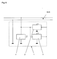
- a bus device provided according to the invention for the transformerless connection to a two-wire bus system BUS of the building system technology has a bus coupling unit 1 which includes a transmission stage 2 and a reception stage 3 and is also equipped with a power supply unit 4 which is the two-wire bus system BUS draws a constant current.
- the high impedance of the receiving stage 3 is realized for example by the use of a Darlington transistor, the high impedance of the output of the transmitting stage 2 through the open collector of the transmitting transistor.
- the high impedance of the power supply unit 4 results from the use of a constant current source.
- Transformerless bus couplers which correspond to the state of the art, are provided on the bus side with a proportionate terminating resistor.
- the parallel connection of all proportional terminating resistors comes in the order of magnitude of the characteristic impedance of the bus line.
- the bus system is designed so that error-free data transmission is ensured even when only two bus devices are connected. Reflections on a long bus line are detected during scanning of the active bit phase by the software of the bus coupler and do not lead to any distortion of the transmitted data. Therefore, it is possible to build the bus devices without a proportionate terminating resistor, without resulting in a deterioration of the transmission characteristics.
- bus devices according to the invention behave in relation to the data transmission as if they did not exist at all, all the circuit characteristics simulating the transformer during the active bit can also be dispensed with.
- the normally necessary for bus couplers of the prior art circuit parts are therefore unnecessary, resulting in a particularly simple and inexpensive constructed and comparatively easy to manufacture bus device leads.
- the current consumption of the bus coupler 1 during data reception during the active phase of the active bit is not influenced by a bus device designed according to the invention. There is no energy absorption from the two-wire bus system BUS caused by the active bit. Likewise, in the course of the subsequent compensation phase no energy recovery, so that the power consumption of the bus coupler 1 during data reception ideally remains constant.
Landscapes
- Engineering & Computer Science (AREA)
- Power Engineering (AREA)
- Computer Networks & Wireless Communication (AREA)
- Signal Processing (AREA)
- Cable Transmission Systems, Equalization Of Radio And Reduction Of Echo (AREA)
Applications Claiming Priority (1)
| Application Number | Priority Date | Filing Date | Title |
|---|---|---|---|
| DE200610026582 DE102006026582A1 (de) | 2006-06-08 | 2006-06-08 | Elektrisches/elektronisches Busgerät |
Publications (2)
| Publication Number | Publication Date |
|---|---|
| EP1865616A2 true EP1865616A2 (fr) | 2007-12-12 |
| EP1865616A3 EP1865616A3 (fr) | 2007-12-19 |
Family
ID=38510428
Family Applications (1)
| Application Number | Title | Priority Date | Filing Date |
|---|---|---|---|
| EP07004985A Ceased EP1865616A3 (fr) | 2006-06-08 | 2007-03-10 | Appareil de bus électrique/électronique |
Country Status (2)
| Country | Link |
|---|---|
| EP (1) | EP1865616A3 (fr) |
| DE (1) | DE102006026582A1 (fr) |
Family Cites Families (3)
| Publication number | Priority date | Publication date | Assignee | Title |
|---|---|---|---|---|
| DE4424907A1 (de) * | 1994-07-14 | 1996-01-18 | Siemens Ag | Bordnetzversorgung bei Busankoppler ohne Übertrager |
| DE59711867D1 (de) * | 1997-01-21 | 2004-09-30 | Siemens Ag | Verfahren und Einrichtung zum übertragerlosen Ankoppeln einer Teilnehmerstation an einem Bus |
| DE10147924B4 (de) * | 2001-09-28 | 2006-03-09 | Siemens Ag | Verfahren und Einrichtung zur übertragerlosen Spannungsversorgung |
-
2006
- 2006-06-08 DE DE200610026582 patent/DE102006026582A1/de not_active Ceased
-
2007
- 2007-03-10 EP EP07004985A patent/EP1865616A3/fr not_active Ceased
Also Published As
| Publication number | Publication date |
|---|---|
| DE102006026582A1 (de) | 2007-12-13 |
| EP1865616A3 (fr) | 2007-12-19 |
Similar Documents
| Publication | Publication Date | Title |
|---|---|---|
| EP1427086B2 (fr) | Appareil électrique et methode pour le faire fonctionner | |
| DE112007001098B4 (de) | Ethernet-Datensignal-Isolationsvorrichtung | |
| DE102007025852B3 (de) | Überwachungseinrichtung zur Erkennung einer fehlerhaften Adressierung eines Aktuator-Sensor-Interface-Slaves | |
| DE102008002946A1 (de) | Verfahren zum Detektieren eines Fehlers auf einer Datenleitung | |
| DE3818601A1 (de) | Digitales signaluebertragungssystem fuer die hausleittechnik | |
| WO2000070764A1 (fr) | Interface de bus compacte a isolement electrique integre | |
| DE102011082172A1 (de) | Leistungsschalter sowie Verfahren zum Überprüfen eines Rogowskiwandlers in einem Leistungsschalter | |
| WO2010049408A1 (fr) | Appareil de mesure modulaire à répartition de données et d'algorithmes | |
| DE102004034248A1 (de) | Elektronische Schaltung mit galvanisch getrennten Baugruppen | |
| DE102005059012B4 (de) | ASI-Sytem zum Anschluß mehrerer Sensoren und/oder Aktuatoren an eine Steuerung | |
| EP1865616A2 (fr) | Appareil de bus électrique/électronique | |
| DE10058793A1 (de) | Datenbus | |
| EP0658866B1 (fr) | Dispositif de transmission à isolement galvanique de signaux de courant continu et alternatif | |
| DE202006021017U1 (de) | Elektrisches/elektronisches Busgerät | |
| EP0637784A1 (fr) | Module avec coupleur pour bus | |
| EP0582257A2 (fr) | Procédé et appareil pour transmettre les informations de signalisation cyclique | |
| DE202022106389U1 (de) | Messende Steckdose sowie Netzwerk von elektrischen/elektronischen Installationsgeräten | |
| EP0798885A2 (fr) | Circuit de couplage entre une ligne de transmission analogique et une ligne de transmission numérique | |
| EP0888588B1 (fr) | Segment ou interface de bus pour connecter un module d'une commande programmable a un bus | |
| DE10257401A1 (de) | Steuerflächennetzwerk (Can) unter Verwendung von Transformatoren | |
| DE102013109544A1 (de) | Aufwachschaltung für elektronische Geräte | |
| EP2001101A1 (fr) | Dispositif d'alimentation en énergie électrique de plusieurs appareils et son procédé de fonctionnement | |
| DE102020115210A1 (de) | Steuersystem für ein mindestens zwei Übertragungsleitungen aufweisendes Bussystem | |
| DE29613185U1 (de) | Trennverstärker | |
| DE102015120319A1 (de) | Induktiver Strommesswandler |
Legal Events
| Date | Code | Title | Description |
|---|---|---|---|
| PUAI | Public reference made under article 153(3) epc to a published international application that has entered the european phase |
Free format text: ORIGINAL CODE: 0009012 |
|
| PUAL | Search report despatched |
Free format text: ORIGINAL CODE: 0009013 |
|
| AK | Designated contracting states |
Kind code of ref document: A2 Designated state(s): AT BE BG CH CY CZ DE DK EE ES FI FR GB GR HU IE IS IT LI LT LU LV MC MT NL PL PT RO SE SI SK TR |
|
| AX | Request for extension of the european patent |
Extension state: AL BA HR MK YU |
|
| AK | Designated contracting states |
Kind code of ref document: A3 Designated state(s): AT BE BG CH CY CZ DE DK EE ES FI FR GB GR HU IE IS IT LI LT LU LV MC MT NL PL PT RO SE SI SK TR |
|
| AX | Request for extension of the european patent |
Extension state: AL BA HR MK YU |
|
| 17P | Request for examination filed |
Effective date: 20080115 |
|
| 17Q | First examination report despatched |
Effective date: 20080214 |
|
| AKX | Designation fees paid |
Designated state(s): AT BE BG CH CY CZ DE DK EE ES FI FR GB GR HU IE IS IT LI LT LU LV MC MT NL PL PT RO SE SI SK TR |
|
| RAP1 | Party data changed (applicant data changed or rights of an application transferred) |
Owner name: INSTA ELEKTRO GMBH |
|
| RAP1 | Party data changed (applicant data changed or rights of an application transferred) |
Owner name: INSTA ELEKTRO GMBH |
|
| STAA | Information on the status of an ep patent application or granted ep patent |
Free format text: STATUS: THE APPLICATION HAS BEEN REFUSED |
|
| 18R | Application refused |
Effective date: 20111127 |