EP1865621B1 - Wiederholer von Funkfrequenzsignalen mobiler Telephonie - Google Patents
Wiederholer von Funkfrequenzsignalen mobiler Telephonie Download PDFInfo
- Publication number
- EP1865621B1 EP1865621B1 EP07109776A EP07109776A EP1865621B1 EP 1865621 B1 EP1865621 B1 EP 1865621B1 EP 07109776 A EP07109776 A EP 07109776A EP 07109776 A EP07109776 A EP 07109776A EP 1865621 B1 EP1865621 B1 EP 1865621B1
- Authority
- EP
- European Patent Office
- Prior art keywords
- antenna
- frequency band
- signals
- mobile telephony
- radiofrequency signals
- Prior art date
- Legal status (The legal status is an assumption and is not a legal conclusion. Google has not performed a legal analysis and makes no representation as to the accuracy of the status listed.)
- Active
Links
Images

Classifications
-
- H—ELECTRICITY
- H04—ELECTRIC COMMUNICATION TECHNIQUE
- H04B—TRANSMISSION
- H04B7/00—Radio transmission systems, i.e. using radiation field
- H04B7/14—Relay systems
- H04B7/15—Active relay systems
- H04B7/155—Ground-based stations
- H04B7/15507—Relay station based processing for cell extension or control of coverage area
- H04B7/15514—Relay station based processing for cell extension or control of coverage area for shadowing compensation
-
- H—ELECTRICITY
- H04—ELECTRIC COMMUNICATION TECHNIQUE
- H04B—TRANSMISSION
- H04B7/00—Radio transmission systems, i.e. using radiation field
- H04B7/14—Relay systems
- H04B7/15—Active relay systems
- H04B7/155—Ground-based stations
- H04B7/15528—Control of operation parameters of a relay station to exploit the physical medium
- H04B7/15542—Selecting at relay station its transmit and receive resources
-
- H—ELECTRICITY
- H04—ELECTRIC COMMUNICATION TECHNIQUE
- H04B—TRANSMISSION
- H04B7/00—Radio transmission systems, i.e. using radiation field
- H04B7/14—Relay systems
- H04B7/15—Active relay systems
- H04B7/155—Ground-based stations
- H04B7/15564—Relay station antennae loop interference reduction
- H04B7/15571—Relay station antennae loop interference reduction by signal isolation, e.g. isolation by frequency or by antenna pattern, or by polarization
Definitions
- the present invention relates to the amplification of mobile radio frequency signals.
- mobile radio frequency signals means any radio frequency signal conveying sound data (voice, music or other), or multimedia (image, sound or other).
- multimedia data may for example comprise SMS ("Short Message Service”) and MMS ("Multimedia Message Service”).
- GSM Global System for Mobile Communications
- a repeater type device it is known to use a repeater type device to amplify radio frequency signals bidirectionally and thus to extend the coverage of a wireless network.
- a repeater can be installed inside a building or in a valley.
- ALR1200 repeater from Powerwave Technologies.
- the figure 1 shows an example of repeater system known from the prior art.
- the repeater 10 comprises a first channel 11 and a second channel 12, respectively intended to be connected to a first antenna 13 and a second antenna 14.
- the antennas 13, 14 operate for example in the GSM band of 900 MHz.
- a first duplexer 15 for example the duplexer 782 10164 of Kathrein, makes it possible to separate downlink radio signals, typically between 935 MHz and 960 MHz, from uplink radio signals, typically between 890 MHz and 915 MHz, respectively received by the antenna 13 and intended to be transformed by the antenna 13 into radio frequency signals.
- the downstream signals arrive on the duplexer 15 and are directed on a downlink 16, on which they are amplified by a first amplifier 17.
- the amplified downstream signals reach a second duplexer 18 and return to the second channel 12, so that the Antenna 14 transmits radio frequency signals corresponding to the downstream signals.
- the upright signals received by the antenna 14 on the second fly 12 arrive at the duplexer 18, pass on an uplink 19 and are amplified by a second amplifier 17 '.
- the amplified upstream signals then pass via the duplexer 15 and are transformed by the antenna 13 into radio frequency signals.
- the antenna 13 is disposed outside the building and the antenna 14 inside the building.
- the document WO 03/051074 describes a system connected on the one hand with a television antenna and a mobile telephone antenna, and on the other with a television set and a mobile telephone antenna.
- a system comprising a repeater and two antennas may be relatively difficult to install, especially when wires have to be pulled between the repeater and the antennas.
- it may be necessary to place an antenna on a roof and connect it to a repeater housing via a coaxial cable.
- the present invention improves the situation. It proposes to lean against a broadcast signal reception facility ("Broadcasting" in English), especially for television, and to take advantage in particular of the antenna of this installation for receiving and transmitting mobile telephony signals.
- Broadcasting in English
- the present invention improves the situation. It proposes to lean against a broadcast signal reception facility ("Broadcasting" in English), especially for television, and to take advantage in particular of the antenna of this installation for receiving and transmitting mobile telephony signals.
- the subject of the invention is a system for amplifying mobile radio frequency signals received in a first frequency band, comprising a repeater device comprising means for bidirectional amplification of radio signals.
- a first antenna and a second antenna are arranged on either side of the repeater device.
- the antennas operate in the first frequency band, the first antenna being arranged to receive further radio frequency broadcast signals in a second frequency band.
- the amplification system thus makes it possible both to receive broadcast signals and to bidirectionally amplify mobile telephony signals.
- Such a system is easier to install than two systems, one for receiving broadcast signals, the other for bidirectional amplification of mobile telephony signals.
- the amplification system according to one aspect of the invention is also less expensive than these two systems, the installation being also less expensive.
- broadcast is not limited to television broadcasting, or television broadcasting, of television programs.
- This term “broadcast” covers, for example, broadcasting ("radio broadcasting” in English), that is to say the audio broadcasting of radio broadcasts, or else the broadcasting of data (“data broadcasting” in English). .
- the present invention is not limited by the mode of operation of bidirectional amplification means, provided that they are suitable for a mobile phone application.
- the repeater device can for example be integrated into a system existing broadcast reception system, the reception system comprising the first antenna, for example a television antenna, and a coaxial cable for connecting the television antenna to a reception module, for example a television set.
- the reception system comprising the first antenna, for example a television antenna, and a coaxial cable for connecting the television antenna to a reception module, for example a television set.
- Most of the buildings are indeed equipped with a television antenna, the establishment of the amplification system is relatively easy. Simply connect the repeater device to the television antenna and then add the second antenna to the repeater device to increase the quality of the mobile telephony signals inside the building.
- DVB-T (acronym for "Digital Video Broadcasting - Terrestrial")
- DVB-T acronym for "Digital Video Broadcasting - Terrestrial”
- decoders in the homes, and sometimes adjustments, even replacements, television antennas.
- an existing repeater system can be modified to integrate a receiving device, the repeater system comprising a repeater and two mobile telephony antennas.
- the repeater system comprising a repeater and two mobile telephony antennas.
- one of these antennas is replaced by an antenna operating in the first and second frequency bands.
- the downstream channel of the repeater can be connected to a receiving module so as to transmit to this module broadcast signals received by the new antenna.
- an amplification system according to the first aspect of the invention comprising the antennas and the repeater device can be installed at one time.
- the present invention is not limited by the nature of the receiving system.
- the first antenna is arranged to receive further radio frequency broadcast signals in a second frequency band.
- the repeater device further comprises third connection means for delivering the signals received by the first antenna in the second frequency band.
- the repeater device makes it possible both to bidirectionally amplify the signals in the first frequency band and to receive the signals in the second frequency band.
- the repeater device integrates a repeater for the mobile telephony signals, and a device for receiving broadcast signals. The implementation is facilitated by reducing the number of devices to install, and the overall cost is reduced.
- the repeater device may comprise means for performing an intermediate frequency conversion in order to facilitate the amplification and filtering functions of the mobile telephony signals, or not to include such means.
- the repeater device may alternatively be selective, that is to say it chooses one (or more) frequency channel among the frequencies of the first frequency band, or non-selective, that is to say that he transmits the whole band.
- the isolation means comprise a coupler, which thus allows a correct isolation between the rising and falling channels, in a relatively simple manner.
- the insulation means are then compact and inexpensive.
- the present invention is not limited by the choice of a coupler.
- the isolation means may comprise a duplexer, which thus guarantees relatively good insulation.
- the repeater device comprises first filtering means arranged to filter the uplink signals received by the second antenna.
- the filtering means may for example have a cut-off frequency outside a sub-band of the first band to which the uplink signals received by the second antenna belong.
- the uplink signals can be filtered at the input of the third connection means. This ensures that the receiving module is protected from rising signals. Indeed, the amplitude of the uplink signals can in certain cases, in particular when a mobile telephone terminal is in a close vicinity of the second antenna, be too high for these to be efficiently filtered by the filters of the modules. existing reception.
- the present invention is not limited by the presence of these first filtering means, in particular, if the repeater device is intended to be connected to a receiving module comprising effective filters for eliminating the mobile telephony signals.
- the repeater device comprises second filtering means having a cut-off frequency between the second frequency band and a sub-band of the first band, to which belong the mobile radio downlink signals.
- the second filtering means thus make it possible to distinguish the mobile telephony signals and the broadcast signals from the descending radioelectric signals.
- the second filtering means may for example be of the bandpass type, with at least one of the cutoff frequencies between the second frequency band and the descending subband of the first band.
- the second filtering means may for example be placed on the downward channel, and be connected to the second connecting means on the one hand and the third connection means of the other.
- the second antenna thus receives no broadcast signals and the reception module does not receive downlink mobile telephony signals.
- the first and second filtering means can also be integrated in a duplexer.
- the duplexer thanks to the first filtering means, makes it possible to protect the third connection means of the upstream signals.
- the second filtering means make it possible to protect the second connection means of the diffusion signals.
- the duplexer thus authorizes only the passage of downlink mobile telephony signals from the downstream channel to the second connection means and the passage of the upstream signals from the second connection means to the upstream channel.
- the present invention is of course not limited by the presence of the second filtering means.
- Most mobile telephone terminals and most television reception modules in fact incorporate sufficiently effective filters to protect themselves from broadcast signals and downlink mobile telephony respectively.
- amplification means and isolation means in a housing, this housing being subsequently connected in situ to the antennas, and possibly to a receiving module, for example a television set.
- the connection of the housing to the second antenna can be done in the factory, and the other connections in situ, for example at home.
- the amplification system shown on the figure 2 comprises a first antenna 23, a repeater device 20 mounted in a housing, a second antenna 24 and a reception module 32.
- the antennas 23, 24 operate in a first frequency band.
- the antenna 23 is also capable of receiving signals in a second frequency band.
- the first frequency band corresponds to a mobile telephony application, for example according to the GSM standard
- the second frequency band corresponds to a broadcast application, here broadcast.
- the receiving module 32 may for example comprise a television set.
- the first frequency band includes the 900 MHz GSM band and the second frequency band includes the UHF (Ultra High Frequencies) band between about 460 MHz and about 860 MHz.
- the first antenna thus operates over a frequency range between about 460 MHz and about 960 MHz.
- Yagi antennas commonly used for terrestrial television generally cover this frequency range.
- another mobile phone standard may be used, for example one of the D-AMPS (acronym for "Digital Analogue Mobile Phone System”), CDMA (acronym for "Code Division Multiple Access”), PDC (acronym for "Personal Digital Cellular”) or another standard involving frequencies close to the high frequencies of the UHF band.
- the mobile telephone standard involves frequencies close to the low frequencies of the UHF band, as is the case, for example, in 450 MHz cellular networks.
- the first band includes a DCS band (acronym for "Digital Communications System”) around 1800 MHz. Conventional television antennas can indeed be able to exploit DCS signals.
- the television antenna 23 is capable of receiving downlink signals in the UHF band (represented by dashed arrows) and downlink GSM signals (represented by solid arrows) in a descending sub-band, substantially between 935 MHz and substantially 960 MHz. These downlink GSM signals are typically transmitted by the various sites of mobile operators licensed in the 900 MHz band.
- the antenna 23 also makes it possible to transmit radiofrequency signals corresponding to upstream GSM signals (represented by dashed arrows), in an upward sub-band, between substantially 890 MHz and substantially 915 MHz.
- the GSM antenna 24 makes it possible to receive the uplink GSM signals and to transmit radio frequency signals corresponding to the downlink GSM signals picked up by the television antenna 23.
- the television set 32 receives the downlink signals in the UHF band.
- the antenna 23 is connected to the device 20 via first connecting means 21, comprising for example a first channel and a plug for receiving a connector of a coaxial cable 34.
- the antenna 24 is connected to the device 20 via second means 22, comprising for example a second channel and an antenna support.
- the television set 32 is connected to the device 20 via third connection means 33, comprising for example a third channel and a plug for receiving a connector of a coaxial cable 35.
- the uplink and downlink signals pass through an uplink 29 and a downlink 26 respectively.
- a first low noise amplifier 27 for amplifying the downlink GSM and UHF signals.
- a second low noise amplifier 27 ' is mounted on the riser 29 so as to amplify the uplink GSM signals.
- Insulation means 25, 31 make it possible to isolate the rising channel 29 from the downward channel 26 and vice versa.
- the isolation means comprise a first coupler 25.
- the antenna 23 is connected to the terminal 1 of this coupler 25, the rising and falling channels being respectively coupled to the terminals 2 and 3 of the coupler 25.
- the coupler 25 makes it possible to ensure a correct isolation between the terminals 2 and 3, that is to say between the rising channel 29 and the downward channel 26.
- the signals which pass on the first channel connecting the antenna 23 to the coupler 25 are shared between the uplink 29 and the downlink 26.
- the repeater device 20 also includes a second coupler.
- the downstream signals arrive from the downstream channel 26 on the terminal 1 of this coupler 30 and are distributed between the terminal 2 and the terminal 3 of the coupler 30. Part of the downstream signals is thus directed towards the television set 32, the other part being directed to a duplexer 31.
- each coupler 25, 30 may be relatively high, typically greater than 20 dB.
- the bandwidth of each coupler 25, 30 and low noise amplifiers 27, 27 ' comprises the frequency range between 460 MHz and 960 MHz.
- Each coupler 25, 30 introduces a loss of about 3 dB.
- couplers marketed by the company Mini-Circuits® under the reference ADP 2-10-75 may be chosen.
- the television set 32 comprises unrepresented filtering means, which makes it possible to discard the downlink and uplink GSM signals from the signals which reach the television set, in order to retain substantially only the UHF signals.
- the duplexer 31 for example the DFYG5902MLEJAA duplexer of the muRata company, effectively isolates the uplink 26 from the downstream path 29 and vice versa.
- the duplexer 31 includes unrepresented filtering means, for example surface acoustic wave (SAW) filters (acronym for "Surface Acoustic Waves") or BAW volume wave filters (acronym for "Bulk Acoustic Waves”), to separate the signals according to their frequency.
- SAW surface acoustic wave
- BAW volume wave filters ascronym for "Bulk Acoustic Waves”
- the downlink GSM signals typically between 935 MHz and 960 MHz, are oriented towards the antenna 24.
- the UHF signals between substantially 460 MHz and substantially 860 MHz, are however filtered by the duplexer 31 and do not pass on the second channel.
- the television set 32 receives the UHF signals amplified by the amplifier 27, thus providing a relatively good quality television reception.
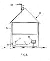
- the figure 3 shows an example of an installation including the amplification system of the figure 2 .
- the repeater device 20 is placed inside a building 40, for example a private dwelling, to allow good GSM reception inside the walls.
- the bidirectional amplification of the device 20 compensates for the propagation attenuation related to the building.
- the gains of the amplifiers 27, 27 'on the figure 2 can for example be between 15 dB and 25 dB.
- the device 20 To install the device 20, simply connect it to the television antenna 23 via the coaxial cable 34.
- Most homes are equipped with a TV socket connected to a television antenna, so one can benefit from a GSM coverage of good quality inside the walls, without the need to pull cables or lay antennas.
Landscapes
- Engineering & Computer Science (AREA)
- Computer Networks & Wireless Communication (AREA)
- Signal Processing (AREA)
- Radio Relay Systems (AREA)
- Mobile Radio Communication Systems (AREA)
Claims (9)
- Verstärkungssystem für in einem ersten Frequenzband empfangene Mobiltelefonie-Radiofrequenzsignale, das enthält• eine erste Antenne (23) und eine zweite Antenne (24), die zum Empfang und zum Senden von Mobiltelefonie-Radiofrequenzsignalen im ersten Frequenzband geeignet sind,• eine mit der ersten und der zweiten Antenne zusammenwirkende Repeater-Vorrichtung (20), die enthält:• Isoliereinrichtungen (25, 30, 31), um die von der zweiten Antenne empfangenen Mobiltelefonie-Radiofrequenzsignale zu einem Upstream-Kanal (29) und die von der ersten Antenne empfangenen Mobiltelefonie-Radiofrequenzsignale zu einem Downstream-Kanal (26) zu lenken, und• bidirektionale Verstärkungseinrichtungen von Funksignalen (27, 27'), um die auf dem Upstream-Kanal und auf dem Downstream-Kanal transportierten Funksignale zu verstärken;und bei dem
die erste Antenne eingerichtet ist, um außerdem Rundfunk-Radiofrequenzsignale in einem zweiten Frequenzband zu empfangen, das vom ersten Frequenzband getrennt ist,
die Repeater-Vorrichtung (20) außerdem Anschlusseinrichtungen (33) aufweist,
wobei die Isoliereinrichtungen (25, 30, 31) geeignet sind, um:• die von der ersten Antenne empfangenen Rundfunk-Radiofrequenzsignale zum Downstream-Kanal zu lenken,• die verstärkten Rundfunk-Radiofrequenzsignale zu den Anschlusseinrichtungen zu lenken. - Verstärkungssystem nach Anspruch 1, bei dem das zweite Frequenzband im Wesentlichen zwischen 460 MHz und 860 MHz liegt.
- Repeater-Vorrichtung (20) für Mobiltelefonie-Signale, die dazu bestimmt ist, im Betrieb verbunden zu werden mit:einer ersten Antenne und mindestens einer zweiten Antenne, die zum Empfang und zum Senden von Mobiltelefonie-Radiofrequenzsignalen in einem ersten Frequenzband geeignet sind,wobei die Vorrichtung mindestens aufweist
erste Anschlusseinrichtungen (21), die mit der ersten Antenne verbunden werden können,
zweite Anschlusseinrichtungen (22), die mit der zweiten Antenne verbunden werden können,
Isoliereinrichtungen (25, 30, 31), um die von der zweiten Antenne empfangenen Mobiltelefonie-Radiofrequenzsignale zu einem Upstream-Kanal (29) zu lenken und die von der ersten Antenne empfangenen Mobiltelefonie-Radiofrequenzsignale zu einem Downstream-Kanal (26) zu lenken, und
bidirektionale Verstärkungseinrichtungen von Funksignalen (27, 27'), um die auf dem Upstream-Kanal und auf dem Downstream-Kanal transportierten Funksignale zu verstärken;
dadurch gekennzeichnet, dass die ersten Anschlusseinrichtungen (21) eingerichtet sind, um im Betrieb außerdem von der ersten Antenne stammende Rundfunksignale in einem zweiten Frequenzband zu empfangen, das vom ersten Frequenzband getrennt ist,
und dass die Isoliereinrichtungen (25, 30, 31) geeignet sind, um zu lenken:• die von der ersten Antenne empfangenen Rundfunksignale zum Downstream-Kanal,• die verstärkten Rundfunksignale zu dritten Anschlusseinrichtungen (33). - Repeater-Vorrichtung (20) nach Anspruch 3, bei der das zweite Frequenzband im Wesentlichen zwischen 460 MHz und 860 MHz liegt.
- Repeater-Vorrichtung (20) nach einem der Ansprüche 3 oder 4, die außerdem enthält:erste Filtereinrichtungen, um die von der zweiten Antenne empfangenen Upstream-Funksignale zu filtern.
- Repeater-Vorrichtung (20) nach einem der Ansprüche 3 bis 5, die außerdem enthält:zweite Filtereinrichtungen, die eine Grenzfrequenz zwischen dem zweiten Frequenzband und einem Teilband des ersten Bands aufweisen, zu dem die Downstream-Mobiltelefonie-Funksignale gehören.
- Repeater-Vorrichtung (20) nach den Ansprüchen 4, 5 und 6, bei der die Isoliereinrichtungen einen Duplexer (31) enthalten, der die ersten und zweiten Filtereinrichtungen umfasst.
- Repeater-Vorrichtung (20) nach einem der Ansprüche 4 bis 7, bei der die Isoliereinrichtungen einen Koppler (25) enthalten.
- Verfahren zur Verstärkung von Mobiltelefonie-Radiofrequenzsignalen in einem Frequenzband und von in einem zweiten Frequenzband getrennt vom ersten empfangenen Rundfunksignalen, das die folgenden Schritte enthält:Lenken der von einer zweiten Antenne empfangenen Mobiltelefonie-Radiofrequenzsignale zu einem Upstream-Kanal (29) und der von einer ersten Antenne empfangenen Mobiltelefonie-Radiofrequenzsignale zu einem Downstream-Kanal (26),Lenken der von der ersten Antenne empfangenen Rundfunksignale zum Downstream-Kanal,Verstärken der auf dem Upstream-Kanal und auf dem Downstream-Kanal transportierten Funksignale,Lenken der verstärkten Rundfunksignale zu Anschlusseinrichtungen.
Applications Claiming Priority (1)
| Application Number | Priority Date | Filing Date | Title |
|---|---|---|---|
| FR0605091 | 2006-06-08 |
Publications (2)
| Publication Number | Publication Date |
|---|---|
| EP1865621A1 EP1865621A1 (de) | 2007-12-12 |
| EP1865621B1 true EP1865621B1 (de) | 2010-05-26 |
Family
ID=37622127
Family Applications (1)
| Application Number | Title | Priority Date | Filing Date |
|---|---|---|---|
| EP07109776A Active EP1865621B1 (de) | 2006-06-08 | 2007-06-07 | Wiederholer von Funkfrequenzsignalen mobiler Telephonie |
Country Status (4)
| Country | Link |
|---|---|
| EP (1) | EP1865621B1 (de) |
| AT (1) | ATE469470T1 (de) |
| DE (1) | DE602007006719D1 (de) |
| ES (1) | ES2346155T3 (de) |
Families Citing this family (1)
| Publication number | Priority date | Publication date | Assignee | Title |
|---|---|---|---|---|
| FR3091088B1 (fr) * | 2018-12-21 | 2021-05-14 | Inst Mines Telecom | "procede pour fournir une connectivite radiomobile dans un espace confine par une antenne de television exterieure et systeme associe" |
Family Cites Families (7)
| Publication number | Priority date | Publication date | Assignee | Title |
|---|---|---|---|---|
| US5638422A (en) * | 1992-01-15 | 1997-06-10 | General Instrument Corp. | Distributed antenna personal communication networks system |
| GB9508901D0 (en) * | 1995-05-02 | 1995-06-21 | Northern Telecom Ltd | Communications system |
| US5918154A (en) * | 1995-08-23 | 1999-06-29 | Pcs Wireless, Inc. | Communications systems employing antenna diversity |
| US5867763A (en) * | 1996-02-08 | 1999-02-02 | Qualcomm Incorporated | Method and apparatus for integration of a wireless communication system with a cable T.V. system |
| JP2000232403A (ja) * | 1999-02-08 | 2000-08-22 | Maspro Denkoh Corp | 有線放送システム,及びヘッドエンド装置,屋内装置 |
| WO2000072466A1 (en) * | 1999-05-20 | 2000-11-30 | Transcept, Inc. | Wide band noise reduction system |
| US20050030915A1 (en) | 2001-12-05 | 2005-02-10 | Harel Golombek | Multi-band cellular service over direct broadcasting service (dbs) network |
-
2007
- 2007-06-07 AT AT07109776T patent/ATE469470T1/de not_active IP Right Cessation
- 2007-06-07 DE DE602007006719T patent/DE602007006719D1/de active Active
- 2007-06-07 EP EP07109776A patent/EP1865621B1/de active Active
- 2007-06-07 ES ES07109776T patent/ES2346155T3/es active Active
Also Published As
| Publication number | Publication date |
|---|---|
| ES2346155T3 (es) | 2010-10-11 |
| EP1865621A1 (de) | 2007-12-12 |
| DE602007006719D1 (de) | 2010-07-08 |
| ATE469470T1 (de) | 2010-06-15 |
Similar Documents
| Publication | Publication Date | Title |
|---|---|---|
| CN1685632A (zh) | 具有数字信道选择器的中继器 | |
| US20160254857A1 (en) | High throughput satellite | |
| FR2897215A1 (fr) | Dispositif et procede d'annulation des interferences | |
| FR2954869A1 (fr) | Installation d'emission/reception de signaux satellitaires | |
| EP1865621B1 (de) | Wiederholer von Funkfrequenzsignalen mobiler Telephonie | |
| CN102668557A (zh) | 保护卫星接收不受强地面信号影响的方法 | |
| EP1331749A1 (de) | Mehrfachsignalübertragungs auf ein Koaxialkabel | |
| EP2587700B1 (de) | Installation für die Aussendung/ den Empfang von Funksignalen | |
| EP3900219B1 (de) | Verfahren um eine mobilfunkverbinbung in einem geschlossenen raum durch eine externe fernsehantenne bereitzustellen und entsprechende vorrichtung | |
| EP2063549B1 (de) | Repeater zur Rückübertragung eines Funksignals vom Typ DVB-H in einer Wohnung | |
| KR100690327B1 (ko) | 건물내 지상파 수신 중계장치 | |
| FR2760930A1 (fr) | Procede de configuration de cellules d'un meme site dans un systeme de radiocommunication numerique cellulaire, et site correspondant | |
| EP1271937A1 (de) | Verfahren zur Gleichfrequenzwiederholungsübertragung von einem terrestrischen digitalen Fernsehsignal | |
| EP1690429B1 (de) | Mobiltelefonnetz für die kommunikation zwischen zwei kommunikationsapparaten | |
| KR100533534B1 (ko) | 방송위성 신호를 연장하는 차량 중계 장치 및 그 방법 | |
| FR2800216A1 (fr) | Dispositif de reception/emission simultanees de signaux comprenant un amplificateur a faible bruit | |
| EP0991215B1 (de) | Aperiodisches modulares System zur Übertragungswiederholung mit mehreren digitalen Kanälen | |
| FR2906422B1 (fr) | Repeteur terrestre multi-entrees pour un systeme de diffusion de contenus | |
| CN1224201C (zh) | Catv网络上的移动无线电通信服务 | |
| FR2879390A1 (fr) | Terminal micro-onde multibandes | |
| FR2988958A1 (fr) | Systeme de communications par liaison lte | |
| KR200421803Y1 (ko) | 차량용 디엠비 증폭기 | |
| FR2888689A1 (fr) | Procede de re emission isofrequence d'un signal numerique a suppression d'echo et dispositif de re-emission correspondant | |
| FR2798793A1 (fr) | Dispositif de supression d'interferences entre deux antennes et son procede associe | |
| EP1490981A1 (de) | Hochfrequenz-duplexsystem und rundsende- oder kommunikationssystem unter benutzung des systems |
Legal Events
| Date | Code | Title | Description |
|---|---|---|---|
| PUAI | Public reference made under article 153(3) epc to a published international application that has entered the european phase |
Free format text: ORIGINAL CODE: 0009012 |
|
| AK | Designated contracting states |
Kind code of ref document: A1 Designated state(s): AT BE BG CH CY CZ DE DK EE ES FI FR GB GR HU IE IS IT LI LT LU LV MC MT NL PL PT RO SE SI SK TR |
|
| AX | Request for extension of the european patent |
Extension state: AL BA HR MK YU |
|
| 17P | Request for examination filed |
Effective date: 20080605 |
|
| 17Q | First examination report despatched |
Effective date: 20080716 |
|
| AKX | Designation fees paid |
Designated state(s): AT BE BG CH CY CZ DE DK EE ES FI FR GB GR HU IE IS IT LI LT LU LV MC MT NL PL PT RO SE SI SK TR |
|
| GRAP | Despatch of communication of intention to grant a patent |
Free format text: ORIGINAL CODE: EPIDOSNIGR1 |
|
| GRAC | Information related to communication of intention to grant a patent modified |
Free format text: ORIGINAL CODE: EPIDOSCIGR1 |
|
| GRAS | Grant fee paid |
Free format text: ORIGINAL CODE: EPIDOSNIGR3 |
|
| GRAA | (expected) grant |
Free format text: ORIGINAL CODE: 0009210 |
|
| AK | Designated contracting states |
Kind code of ref document: B1 Designated state(s): AT BE BG CH CY CZ DE DK EE ES FI FR GB GR HU IE IS IT LI LT LU LV MC MT NL PL PT RO SE SI SK TR |
|
| REG | Reference to a national code |
Ref country code: GB Ref legal event code: FG4D Free format text: NOT ENGLISH |
|
| REG | Reference to a national code |
Ref country code: CH Ref legal event code: EP |
|
| REG | Reference to a national code |
Ref country code: IE Ref legal event code: FG4D Free format text: LANGUAGE OF EP DOCUMENT: FRENCH |
|
| REF | Corresponds to: |
Ref document number: 602007006719 Country of ref document: DE Date of ref document: 20100708 Kind code of ref document: P |
|
| REG | Reference to a national code |
Ref country code: NL Ref legal event code: VDEP Effective date: 20100526 |
|
| REG | Reference to a national code |
Ref country code: ES Ref legal event code: FG2A Ref document number: 2346155 Country of ref document: ES Kind code of ref document: T3 |
|
| LTIE | Lt: invalidation of european patent or patent extension |
Effective date: 20100526 |
|
| PG25 | Lapsed in a contracting state [announced via postgrant information from national office to epo] |
Ref country code: LT Free format text: LAPSE BECAUSE OF FAILURE TO SUBMIT A TRANSLATION OF THE DESCRIPTION OR TO PAY THE FEE WITHIN THE PRESCRIBED TIME-LIMIT Effective date: 20100526 Ref country code: SE Free format text: LAPSE BECAUSE OF FAILURE TO SUBMIT A TRANSLATION OF THE DESCRIPTION OR TO PAY THE FEE WITHIN THE PRESCRIBED TIME-LIMIT Effective date: 20100526 |
|
| PG25 | Lapsed in a contracting state [announced via postgrant information from national office to epo] |
Ref country code: AT Free format text: LAPSE BECAUSE OF FAILURE TO SUBMIT A TRANSLATION OF THE DESCRIPTION OR TO PAY THE FEE WITHIN THE PRESCRIBED TIME-LIMIT Effective date: 20100526 Ref country code: FI Free format text: LAPSE BECAUSE OF FAILURE TO SUBMIT A TRANSLATION OF THE DESCRIPTION OR TO PAY THE FEE WITHIN THE PRESCRIBED TIME-LIMIT Effective date: 20100526 Ref country code: SI Free format text: LAPSE BECAUSE OF FAILURE TO SUBMIT A TRANSLATION OF THE DESCRIPTION OR TO PAY THE FEE WITHIN THE PRESCRIBED TIME-LIMIT Effective date: 20100526 Ref country code: LV Free format text: LAPSE BECAUSE OF FAILURE TO SUBMIT A TRANSLATION OF THE DESCRIPTION OR TO PAY THE FEE WITHIN THE PRESCRIBED TIME-LIMIT Effective date: 20100526 Ref country code: IS Free format text: LAPSE BECAUSE OF FAILURE TO SUBMIT A TRANSLATION OF THE DESCRIPTION OR TO PAY THE FEE WITHIN THE PRESCRIBED TIME-LIMIT Effective date: 20100926 |
|
| BERE | Be: lapsed |
Owner name: FRANCE TELECOM Effective date: 20100630 |
|
| PG25 | Lapsed in a contracting state [announced via postgrant information from national office to epo] |
Ref country code: CY Free format text: LAPSE BECAUSE OF FAILURE TO SUBMIT A TRANSLATION OF THE DESCRIPTION OR TO PAY THE FEE WITHIN THE PRESCRIBED TIME-LIMIT Effective date: 20100526 Ref country code: PL Free format text: LAPSE BECAUSE OF FAILURE TO SUBMIT A TRANSLATION OF THE DESCRIPTION OR TO PAY THE FEE WITHIN THE PRESCRIBED TIME-LIMIT Effective date: 20100526 |
|
| REG | Reference to a national code |
Ref country code: IE Ref legal event code: FD4D |
|
| PG25 | Lapsed in a contracting state [announced via postgrant information from national office to epo] |
Ref country code: PT Free format text: LAPSE BECAUSE OF FAILURE TO SUBMIT A TRANSLATION OF THE DESCRIPTION OR TO PAY THE FEE WITHIN THE PRESCRIBED TIME-LIMIT Effective date: 20100927 Ref country code: MC Free format text: LAPSE BECAUSE OF NON-PAYMENT OF DUE FEES Effective date: 20100630 Ref country code: EE Free format text: LAPSE BECAUSE OF FAILURE TO SUBMIT A TRANSLATION OF THE DESCRIPTION OR TO PAY THE FEE WITHIN THE PRESCRIBED TIME-LIMIT Effective date: 20100526 Ref country code: DK Free format text: LAPSE BECAUSE OF FAILURE TO SUBMIT A TRANSLATION OF THE DESCRIPTION OR TO PAY THE FEE WITHIN THE PRESCRIBED TIME-LIMIT Effective date: 20100526 Ref country code: NL Free format text: LAPSE BECAUSE OF FAILURE TO SUBMIT A TRANSLATION OF THE DESCRIPTION OR TO PAY THE FEE WITHIN THE PRESCRIBED TIME-LIMIT Effective date: 20100526 Ref country code: IE Free format text: LAPSE BECAUSE OF FAILURE TO SUBMIT A TRANSLATION OF THE DESCRIPTION OR TO PAY THE FEE WITHIN THE PRESCRIBED TIME-LIMIT Effective date: 20100526 |
|
| PG25 | Lapsed in a contracting state [announced via postgrant information from national office to epo] |
Ref country code: SK Free format text: LAPSE BECAUSE OF FAILURE TO SUBMIT A TRANSLATION OF THE DESCRIPTION OR TO PAY THE FEE WITHIN THE PRESCRIBED TIME-LIMIT Effective date: 20100526 Ref country code: RO Free format text: LAPSE BECAUSE OF FAILURE TO SUBMIT A TRANSLATION OF THE DESCRIPTION OR TO PAY THE FEE WITHIN THE PRESCRIBED TIME-LIMIT Effective date: 20100526 Ref country code: CZ Free format text: LAPSE BECAUSE OF FAILURE TO SUBMIT A TRANSLATION OF THE DESCRIPTION OR TO PAY THE FEE WITHIN THE PRESCRIBED TIME-LIMIT Effective date: 20100526 |
|
| PG25 | Lapsed in a contracting state [announced via postgrant information from national office to epo] |
Ref country code: IT Free format text: LAPSE BECAUSE OF NON-PAYMENT OF DUE FEES Effective date: 20100607 |
|
| PLBE | No opposition filed within time limit |
Free format text: ORIGINAL CODE: 0009261 |
|
| STAA | Information on the status of an ep patent application or granted ep patent |
Free format text: STATUS: NO OPPOSITION FILED WITHIN TIME LIMIT |
|
| PG25 | Lapsed in a contracting state [announced via postgrant information from national office to epo] |
Ref country code: MT Free format text: LAPSE BECAUSE OF FAILURE TO SUBMIT A TRANSLATION OF THE DESCRIPTION OR TO PAY THE FEE WITHIN THE PRESCRIBED TIME-LIMIT Effective date: 20100526 Ref country code: GR Free format text: LAPSE BECAUSE OF FAILURE TO SUBMIT A TRANSLATION OF THE DESCRIPTION OR TO PAY THE FEE WITHIN THE PRESCRIBED TIME-LIMIT Effective date: 20100827 |
|
| 26N | No opposition filed |
Effective date: 20110301 |
|
| REG | Reference to a national code |
Ref country code: DE Ref legal event code: R097 Ref document number: 602007006719 Country of ref document: DE Effective date: 20110228 |
|
| PG25 | Lapsed in a contracting state [announced via postgrant information from national office to epo] |
Ref country code: BE Free format text: LAPSE BECAUSE OF NON-PAYMENT OF DUE FEES Effective date: 20100630 |
|
| REG | Reference to a national code |
Ref country code: CH Ref legal event code: PL |
|
| PG25 | Lapsed in a contracting state [announced via postgrant information from national office to epo] |
Ref country code: CH Free format text: LAPSE BECAUSE OF NON-PAYMENT OF DUE FEES Effective date: 20110630 Ref country code: LI Free format text: LAPSE BECAUSE OF NON-PAYMENT OF DUE FEES Effective date: 20110630 |
|
| PG25 | Lapsed in a contracting state [announced via postgrant information from national office to epo] |
Ref country code: LU Free format text: LAPSE BECAUSE OF NON-PAYMENT OF DUE FEES Effective date: 20100607 Ref country code: BG Free format text: LAPSE BECAUSE OF FAILURE TO SUBMIT A TRANSLATION OF THE DESCRIPTION OR TO PAY THE FEE WITHIN THE PRESCRIBED TIME-LIMIT Effective date: 20100526 Ref country code: HU Free format text: LAPSE BECAUSE OF FAILURE TO SUBMIT A TRANSLATION OF THE DESCRIPTION OR TO PAY THE FEE WITHIN THE PRESCRIBED TIME-LIMIT Effective date: 20101127 |
|
| PG25 | Lapsed in a contracting state [announced via postgrant information from national office to epo] |
Ref country code: TR Free format text: LAPSE BECAUSE OF FAILURE TO SUBMIT A TRANSLATION OF THE DESCRIPTION OR TO PAY THE FEE WITHIN THE PRESCRIBED TIME-LIMIT Effective date: 20100526 |
|
| PG25 | Lapsed in a contracting state [announced via postgrant information from national office to epo] |
Ref country code: BG Free format text: LAPSE BECAUSE OF FAILURE TO SUBMIT A TRANSLATION OF THE DESCRIPTION OR TO PAY THE FEE WITHIN THE PRESCRIBED TIME-LIMIT Effective date: 20100826 |
|
| REG | Reference to a national code |
Ref country code: FR Ref legal event code: PLFP Year of fee payment: 9 |
|
| REG | Reference to a national code |
Ref country code: FR Ref legal event code: PLFP Year of fee payment: 10 |
|
| REG | Reference to a national code |
Ref country code: FR Ref legal event code: PLFP Year of fee payment: 11 |
|
| REG | Reference to a national code |
Ref country code: FR Ref legal event code: PLFP Year of fee payment: 12 |
|
| PGFP | Annual fee paid to national office [announced via postgrant information from national office to epo] |
Ref country code: DE Payment date: 20250520 Year of fee payment: 19 |
|
| PGFP | Annual fee paid to national office [announced via postgrant information from national office to epo] |
Ref country code: GB Payment date: 20250520 Year of fee payment: 19 |
|
| PGFP | Annual fee paid to national office [announced via postgrant information from national office to epo] |
Ref country code: IT Payment date: 20250520 Year of fee payment: 19 |
|
| PGFP | Annual fee paid to national office [announced via postgrant information from national office to epo] |
Ref country code: FR Payment date: 20250520 Year of fee payment: 19 |
|
| PGFP | Annual fee paid to national office [announced via postgrant information from national office to epo] |
Ref country code: ES Payment date: 20250701 Year of fee payment: 19 |