EP1867258A2 - Pulverisierender Produktverteiler mit abnehmbaren Behälter - Google Patents
Pulverisierender Produktverteiler mit abnehmbaren Behälter Download PDFInfo
- Publication number
- EP1867258A2 EP1867258A2 EP07356079A EP07356079A EP1867258A2 EP 1867258 A2 EP1867258 A2 EP 1867258A2 EP 07356079 A EP07356079 A EP 07356079A EP 07356079 A EP07356079 A EP 07356079A EP 1867258 A2 EP1867258 A2 EP 1867258A2
- Authority
- EP
- European Patent Office
- Prior art keywords
- housing
- reservoir
- flap
- dispenser according
- tank
- Prior art date
- Legal status (The legal status is an assumption and is not a legal conclusion. Google has not performed a legal analysis and makes no representation as to the accuracy of the status listed.)
- Withdrawn
Links
Images


Classifications
-
- A—HUMAN NECESSITIES
- A47—FURNITURE; DOMESTIC ARTICLES OR APPLIANCES; COFFEE MILLS; SPICE MILLS; SUCTION CLEANERS IN GENERAL
- A47J—KITCHEN EQUIPMENT; COFFEE MILLS; SPICE MILLS; APPARATUS FOR MAKING BEVERAGES
- A47J31/00—Apparatus for making beverages
- A47J31/40—Beverage-making apparatus with dispensing means for adding a measured quantity of ingredients, e.g. coffee, water, sugar, cocoa, milk, tea
- A47J31/404—Powder dosing devices
Definitions
- the present invention relates to a powdery product dispensing device comprising a removable reservoir for a powdered infusion or percolation food product, such as ground coffee, tea, chocolate, etc. and suitable for use with a beverage preparation and dispensing apparatus.
- a powdery product dispensing device comprising a removable reservoir for a powdered infusion or percolation food product, such as ground coffee, tea, chocolate, etc. and suitable for use with a beverage preparation and dispensing apparatus.
- An apparatus for preparing and dispensing hot drinks for example from ground coffee, generally comprises a cold water tank, an electric pump, a boiler and an infusion head adapted to receive a certain quantity of ground coffee. for injecting a predetermined amount of hot water from the boiler, the resulting beverage is then directed to a collection vessel. At the end of the infusion cycle, the infusion head must be opened in order to introduce a new dose of ground coffee after evacuating the rest of previously infused product. The ground coffee is fed into the brewing chamber from a powder product dispenser. These devices require a regular filling of the dispenser tank, maneuver that requires time and a lot of attention from the user, especially when access to the tank is in a small space.
- the document DE 203 00 928 U1 discloses another removable coffee bean tank solution for a coffee machine having a central opening closed by two arcuate shutters rotated relative to each other when the tank is rotated around its center. vertical axis inside the machine.
- this solution has the disadvantage of being able to be used with coffee beans larger in size than the orifice existing between the two flaps when they are in their closed position.
- it proves not only complex construction, but also complicated use for the user who must then turn itself the tank, going through several phases of rotation, each corresponding to a specific function: setting up the tank, then several possibilities of opening flaps, then closing by turning in the other direction, etc.
- the object of the invention is to overcome the aforementioned drawbacks and to propose a dispenser of pulverulent product with a removable reservoir which allows the user to easily install the reservoir relative to the dispenser and to withdraw it safely in a easy and intuitive, for a simplified and reliable constructive solution in operation.
- Another object of the invention is a pulverulent product dispenser with a removable reservoir comprising a dispensing orifice capable of being opened and closed automatically.
- Another object of the invention is a pulverulent product dispenser with removable reservoir comprising an automatic closure system of its simplified construction dispensing orifice, easy to industrialize for lower costs, while being reliable in operation.
- a powdery product dispenser comprising a housing, a tank removably mounted in a housing made in the housing, containing the powdery product and having a dispensing orifice, and a shutter device of this orifice comprising at least one flap carried by the reservoir and mounted movably between a closed position of the dispensing orifice and an opening position of this orifice, because the introduction by vertical translation of the reservoir in the housing housing triggers the displacement of the shutter from its closed position to its open position.
- Such a powdery product dispenser is preferably used with a machine for preparing beverages, the powdery product can be coffee beans or ground coffee, tea, chocolate, etc.
- the dispenser comprises a reservoir of powdery product provided with a dispensing orifice and a shutter device of this orifice, the tank allowing, thanks to its removability, to easily switch from one type of powdery product to another, by simple change of reservoir.
- the reservoir being removable, the dispensing or outlet orifice of the reservoir is kept closed when the reservoir is outside the dispenser, thereby avoiding the risk of powdery product flow during the withdrawal and handling of the tank containing the product.
- the shutter device of the dispensing orifice cooperates with actuating means enabling a closing flap of the dispenser orifice to automatically move from a closed position, when the reservoir is out of the housing, in an open position, when the reservoir is positioned in its housing within the dispenser.
- the opening of the dispensing orifice occurs automatically at the same time as the installation of the reservoir by vertical translation in its housing provided for this purpose in the dispenser housing, a housing that can be, for example, connected to that belonging to a machine for preparing drinks.
- the introduction of the tank in its housing by a linear downward movement automatically moves the flap from its closed position to an open position so that at the end of its downhill stroke to the inside its housing, the tank is already in the operating position.
- the installation of the tank inside its housing is advantageously by a vertical downward translation, this already requiring less effort on the part of the user, the tank taking its place naturally, simply by descending into the housing under the influence of its weight.
- the user only has to correctly position the tank relative to the upper opening of its housing inside the housing of the machine, then simply let it slide vertically inside this housing, where it takes place under the effect of its own weight. There is therefore no longer the obligation for the user to have to handle the tank or its components after the end of its descent stroke in the housing of the machine, or to have to control by a lever or command button the opening of the dispensing orifice of the reservoir, the latter being guaranteed by the simple setting in position by vertical translation of the reservoir in its housing.
- This greatly simplifies the construction of the dispenser and its reservoir and especially the operation of setting up and removing the reservoir relative to the machine, which then proves to be very intuitive operation. In addition, it avoids any risk of manipulation or mishandling on the part of the user, including a possible omission of operation of the opening which could then cause malfunctions of the dispenser or the machine with it.
- the flap is actuated towards its closed position by a return spring when the reservoir is removed from the housing.
- This solution makes it possible to automatically close the product outlet orifice of the reservoir when it is withdrawn from the housing and to keep the reservoir containing the powdery product closed when it is transported or stored outside the dispenser, while being easy to put on. implemented.
- the housing of the housing comprises a cam cooperating with the periphery of the flap.
- the flap comprises a rib engaging in a slot in a wall of the housing.
- the slot in a wall thereof is both easily identifiable from the upper portion of the housing and may, in addition, present in this same upper part, a chamfer introduction of the rib of the flap.
- the introduction by translation of the reservoir in the housing of the housing triggers the rotational movement of the flap.
- the flap is rotatably mounted at the bottom of the tank, being rotated about the longitudinal axis of the latter.
- Such a flap mounted at the bottom of the tank allows to evacuate its entire contents.
- a flap rotating around the longitudinal axis of the reservoir can advantageously be used with a generally cylindrical tank.
- the dispensing orifice is a window formed in a cylindrical side wall of the reservoir and extending on a bottom wall of the reservoir.
- Such a dispensing orifice made in the lower part of a side wall of the tank and extending on the bottom wall of the tank allows to distribute a large volume of product for a small displacement of the flap, including a low angle of rotation of the flap .
- the flap pivots outside the reservoir and has a guide pin in a groove of the reservoir.
- the pivoting of the flap outside the tank ensures a very good closure of the dispensing orifice for easier mounting of the flap relative to the tank.
- the flap is made to ensure an airtight closure of the tank.
- the walls of the shutter have a shape and dimensions corresponding to those of the dispensing orifice and the flap is mounted relative to the reservoir with a very small clearance, so as to ensure an airtight closure of the reservoir and thus prevent the oxidation of the product contained in the reservoir and its preservation outside the dispenser.
- the reservoir comprises indexing means in position relative to the housing of the housing.
- the tank contains coffee grounds and the dispenser comprises metering means for delivering defined quantities of ground coffee.
- the tank contains coffee beans and the coffee machine comprises means for grinding said beans and delivering the grind.
- the dispenser removable reservoir of the invention can therefore be used with tanks containing grind or coffee beans, indifferently, so with different categories of machines.
- the removable tank dispenser of the invention is advantageously used in an automatic machine for preparing beverages.
- Such an automatic machine comprises means for supplying a predetermined quantity of fluid inside an infusion chamber receiving the powdery product delivered by the distributor of the invention, as well as means for evacuation of the product. infusion outside the brewing chamber in the direction of a collecting vessel.
- the removable tank dispenser of the invention makes it possible to close and open the outlet orifice of powdery product without user intervention, to avoid the risks of fouling when removing the tank, to better preserve the taste and the aroma of the product when stored outside the machine, while allowing the machine to produce several types of drinks from interchangeable removable tanks.
- a coffee machine incorporating a powdery product dispenser according to the invention comprises the known elements encountered in this category of machines and can incorporate the specificities described in the document.
- WO 9912457 as regards the device for compacting the coffee grounds in the brewing chamber and for the ejection of the coffee cakes.
- Such a machine is particularly suitable for ensuring the adequate temperature of the water fed into the brewing chamber and capable of compacting the grinding inside the brewing chamber.
- the coffee obtained after the infusion of the ground coffee into the chamber is discharged outside the machine in a collecting container, as for example described in the document WO 9912456 .
- the pulverulent product dispenser described furthermore comprises dosing means, in particular a hub which rotates the dosing blades to deliver defined quantities of ground coffee, these means comprising known elements and capable of incorporating the specificities described in the document. FR 2,713,906 .
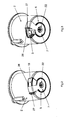
- the ground coffee dispenser comprises a tank 2 of generally cylindrical shape including a dispensing orifice 3 at its lower part and a closure device 5 of this orifice with a flap 7.
- the reservoir 2 comprises a lateral wall 14 of generally cylindrical shape, a bottom wall 15 and an upper rim 16 adapted to receive a removable cover (not shown).
- a protuberance 17a is formed on one side of the upper flange 16 and extends downwards by a semi-cylindrical protuberance 17b on one side of the reservoir 2, the protuberance 17b forming an indexing means of the reservoir 2 when it is in place. in a housing provided for this purpose in the coffee machine, as will be described later.
- the bottom wall 15 is made in a separate part nested on the side wall 14 and has a central orifice 18.
- the dispensing orifice 3 is formed on one side of the reservoir 2, and is in the form of a corner window 4 which has a rectangular shape in the lower part of the side wall 14 and which is extended by an opening in the form of a circular sector of an angle of about 30 ° on the bottom wall 15.
- the dispensing orifice 3 extends laterally on one side by a cutout 19, the same width as that of the dispensing orifice 3, being practiced on a small thickness in the outer surface of the tank 2 and for housing the flap 7, as will be explained later.
- a groove 26 borders the upper part of the blank 19, being parallel to the bottom wall 15, and extends above the dispensing orifice 3.
- the flap 7 has a base 20 of generally circular shape with an external diameter corresponding to that of the central orifice 18.
- the flap 7 is fixed to the bottom wall 15 of the tank 2 by means of mounting lugs 21, the lugs of the legs mounting 21 in the bottom wall 15 allowing the rotation of the flap 7 about the vertical axis of the tank 2 passing through the center of the orifice 18.
- An opening 22 in the center of the base 20 of the flap allows the passage of a rotating drive shaft (not shown), from the machine housing, of a hub 23 carrying metering blades (not shown) inside the distributor 1.
- the base 20 of the flap is extended radially on one side by a corner hatch 25 having the same shape, but slightly larger dimensions than those of the corner window 4 of the tank 2 it covers.
- the vertical side wall of the corner hatch 25 has a vertical protruding rib 27 of constant thickness over the entire height of this side wall of the hatch.
- the flap 7 is mounted elastically with respect to the reservoir 2, by means of a torsion return spring 24 (FIG 1a), the spring being located between the bottom wall 15 and the base 20 of the flap 7. More particularly , the return spring 24 has a general shape of concentric loop in the center of the orifice 18, one of its ends being fixed to the bottom wall 15 and the other end being fixed to the base 20 of the flap 7. In the rest position, the return spring 24 maintains the shutter 7 in the closed position relative to the dispensing orifice 3, the angle window 4 being sealed by the angle hatch 25.
- the tank 2 is removably mounted in a housing 9 of a housing 10 of the coffee machine dispenser, which housing is supported by the upper part of the frame of the machine.
- an outlet opening 30 is seen located at the bottom of the housing 9 communicating, via a chute, with the infusion chamber (not shown) and allowing, after the introduction of the reservoir 2 in the housing 9, the flow of the ground coffee towards the brewing chamber of the machine.
- the housing 9 has, on one side, a notch 31 for receiving the protuberance 17b of the tank 2 allowing a correct and rapid positioning thereof relative to the housing 9 and preventing rotation of the tank relative to the housing 9.
- the introduction by vertical translation of the reservoir 2 in its housing 9 triggers the rotational movement of the flap 7 about the longitudinal or vertical axis of the reservoir.
- the housing 9 comprises a cam 32 cooperating with the periphery of the flap 7 when the reservoir is inserted into the housing 9 of the housing 10.
- a cavity or slot 33 is formed in the lateral inner wall 11 of the housing 9 and has a first oblique portion 33a extended towards the bottom of the housing by a vertical portion 33b, the oblique portions 33a and vertical 33b forming cam surfaces.
- the slot 33 is positioned relative to the notch 31 so as to come into contact with the rib 27 of the flap 7 of the reservoir 2 when the latter is positioned in its housing 9, the flap 7 being in the closed position.
- the rib 27 of the flap 7 bears on the slot 33 forming a cam ramp which pushes the flap 7 pivotally against the force of the return spring 24 during the vertical descent of the tank 2 in the housing 9.
- the shutter is guided pivoting by a lug 35 (FIG 4) internal sliding in the groove 26 of the reservoir 2, the return spring 24 maintaining the rib 27 in contact with the sides of the slot 33.
- Figure 4 shows a top view of the dispenser housing mounted in the housing of a coffee machine with the reservoir removed for clarity.
- the distributor tank When the distributor tank is in position in its housing 9 within the coffee machine, the rib 27 of the flap 7 is at the vertical part of the slot 33, and the corner window 25 of the flap 7 is pivotally offset to cover the cutout 19 of the tank leaving completely free the dispensing orifice 3 located vis-à-vis the outlet opening 30 and thus allowing the flow of coffee towards the chamber of infusion.
- Figures 2 and 3 show the reservoir 2 in the two extreme operating positions of the shutter device 5 of the dispenser of the invention.
- Figure 2 shows the reservoir 2 when removed from the machine, the flap 7 having completely closed the dispensing orifice, leaving the cutout 19 completely uncovered.
- the tank 2 is thus ready for transport or for storage.
- Figure 3 shows the tank 2 in its operating position within the coffee machine. It is observed, contrary to FIG. 2, that the flap 7 has shifted to the right, superimposed on the cutout 19 of FIG. 2 to completely open the dispensing orifice 3.
- the user begins by choosing the type of grinding desired, then fills the tank 2 and then positions it in the housing 9 of the housing 10 of the distributor.
- the rib 27 of the flap 7 coming into contact with the slot 33 of the cam 32 makes it possible to shift the flap which opens the dispensing orifice 3 to make it communicate with the outlet opening 30 at the bottom of the housing 9.
- the machine is ready for operation, the user can control an infusion cycle.
- the control of the infusion cycle sets the dosing blades of the dispenser which distribution 3 a dose of ground coffee inside the brewing chamber.
- a tamping piston compresses the grind and a predetermined amount of hot water is fed from a boiler into the infusion chamber, and the beverage obtained by passing through the grind is collected outside the machine. This infusion cycle completed, the user can remove the removable tank 2 of the machine, the return spring 24 of the flap 7 then automatically closing the dispensing orifice 3.
- any other type of movable flap associated with tanks of various shapes such as a sliding shutter on a flat wall of a parallelepiped tank, or on a bottom wall of the tank, etc., can be used.
Landscapes
- Engineering & Computer Science (AREA)
- Food Science & Technology (AREA)
- Apparatus For Making Beverages (AREA)
- Closures For Containers (AREA)
Applications Claiming Priority (1)
| Application Number | Priority Date | Filing Date | Title |
|---|---|---|---|
| FR0605346A FR2902303B1 (fr) | 2006-06-15 | 2006-06-15 | Distributeur de produit pulverulent a reservoir amovible |
Publications (2)
| Publication Number | Publication Date |
|---|---|
| EP1867258A2 true EP1867258A2 (de) | 2007-12-19 |
| EP1867258A3 EP1867258A3 (de) | 2012-01-25 |
Family
ID=37897737
Family Applications (1)
| Application Number | Title | Priority Date | Filing Date |
|---|---|---|---|
| EP07356079A Withdrawn EP1867258A3 (de) | 2006-06-15 | 2007-06-13 | Pulverisierender Produktverteiler mit abnehmbaren Behälter |
Country Status (3)
| Country | Link |
|---|---|
| US (1) | US7975882B2 (de) |
| EP (1) | EP1867258A3 (de) |
| FR (1) | FR2902303B1 (de) |
Cited By (4)
| Publication number | Priority date | Publication date | Assignee | Title |
|---|---|---|---|---|
| WO2013014040A1 (en) * | 2011-07-28 | 2013-01-31 | Nestec S.A. | Beverage dispenser with automatic closure of the powder containers chutes |
| ITUB20160831A1 (it) * | 2016-02-19 | 2016-05-19 | Sandenvendo Europe S P A | Contenitore di sostanza di ingredienti per preparare bevande. |
| EP3135161A1 (de) * | 2015-08-26 | 2017-03-01 | Bernd Müller | Kaffeebohnenbehälter, kaffeebrühvorrichtung damit und kaffeebrühverfahren |
| ITUA20161566A1 (it) * | 2016-03-11 | 2017-09-11 | De Longhi Appliances Srl | Macchina da caffè incorporante un macinino |
Families Citing this family (13)
| Publication number | Priority date | Publication date | Assignee | Title |
|---|---|---|---|---|
| WO2009035920A2 (en) * | 2007-09-11 | 2009-03-19 | Johnsondiversey, Inc. | Dispenser system and method |
| US8047408B2 (en) * | 2008-07-17 | 2011-11-01 | Prince Castle LLC | Dispenser for granules and powders |
| CA2738727C (en) | 2008-09-17 | 2018-01-02 | Sara Lee/De N.V. | System for preparing a coffee beverage |
| WO2011082254A1 (en) * | 2009-12-31 | 2011-07-07 | Abbott Laboratories | Dispensing appliance for dispensing a beverage from a powdered beverage container |
| US20120017765A1 (en) * | 2010-07-21 | 2012-01-26 | Simatelex Manufactory Co. Ltd. | Coffee maker having a bean grinder and coffee bean grinder |
| ES2553865T3 (es) * | 2011-10-21 | 2015-12-14 | Koninklijke Philips N.V. | Un dispositivo para separar dos espacios entre sí |
| US9222231B2 (en) * | 2013-03-15 | 2015-12-29 | Fred Marconi | Electrically powered hand spreader |
| CN107049028B (zh) * | 2017-02-27 | 2025-02-18 | 深圳前海小智萌品科技有限公司 | 冲调漏斗组件和冲奶机 |
| EP3384815A1 (de) * | 2017-04-05 | 2018-10-10 | Nestec S.A. | Spender für schüttgut |
| JP6671659B2 (ja) * | 2017-08-07 | 2020-03-25 | 株式会社Tree Field | 飲料製造装置 |
| CN112638216B (zh) * | 2018-07-06 | 2024-12-27 | 阳光股份有限责任公司 | 食品处理系统 |
| IT201900019088A1 (it) * | 2019-10-16 | 2021-04-16 | La Marzocco Srl | Tramoggia per macchina macina caffè dotata di dispositivo di chiusura inferiore salva chicchi e macchina macina caffè dotata di tale tramoggia |
| CN113979222B (zh) * | 2021-09-28 | 2023-05-23 | 张家港宏昌钢板有限公司 | 一种快速可拆装线材集卷分配器 |
Family Cites Families (12)
| Publication number | Priority date | Publication date | Assignee | Title |
|---|---|---|---|---|
| US3123107A (en) * | 1964-03-03 | Particulate material transfer | ||
| US2138204A (en) | 1936-07-09 | 1938-11-29 | Enterprise Mfg Co | Coffee mill |
| US4169051A (en) * | 1976-06-22 | 1979-09-25 | Eisai Co., Ltd. | Blood purification with coated activated carbon spheres |
| US4173101A (en) * | 1977-11-07 | 1979-11-06 | Wingerden Aart Van | Greenhouse gutter assembly |
| DE2926389A1 (de) * | 1979-06-29 | 1981-01-15 | Bosch Siemens Hausgeraete | Kaffeemuehle |
| US5125438A (en) * | 1989-03-27 | 1992-06-30 | Deere & Company | Closed granular chemical handling system |
| WO2000065969A1 (en) | 1999-04-30 | 2000-11-09 | Food Equipment Technologies, Inc. | Food ingredient grinder removable ingredient hopper and method |
| US6698624B2 (en) * | 2001-04-04 | 2004-03-02 | Nestec S.A. | Device for dispensing a flowable powder substance |
| CA2411809C (en) * | 2002-11-08 | 2009-06-23 | Vki Technologies Inc. | Systems useful for beverage making machines |
| DE20300928U1 (de) * | 2003-01-22 | 2004-05-27 | Wik Far East Ltd. | Kaffeebohnenbehälter für einen Kaffeeautomaten |
| US6868988B2 (en) * | 2003-02-28 | 2005-03-22 | Nestec S.A. | Containers of flowable substance adapted for connecting to dispensing devices of a beverage or food dispensing machine |
| MXPA05011309A (es) * | 2003-04-23 | 2006-03-08 | Bunn O Matic Corp | Molino de tolva removible. |
-
2006
- 2006-06-15 FR FR0605346A patent/FR2902303B1/fr not_active Expired - Lifetime
-
2007
- 2007-06-13 EP EP07356079A patent/EP1867258A3/de not_active Withdrawn
- 2007-06-15 US US11/763,737 patent/US7975882B2/en not_active Expired - Fee Related
Cited By (10)
| Publication number | Priority date | Publication date | Assignee | Title |
|---|---|---|---|---|
| WO2013014040A1 (en) * | 2011-07-28 | 2013-01-31 | Nestec S.A. | Beverage dispenser with automatic closure of the powder containers chutes |
| CN103841863A (zh) * | 2011-07-28 | 2014-06-04 | 雀巢产品技术援助有限公司 | 具有自动闭合的粉末容器滑槽的饮料分配机 |
| CN103841863B (zh) * | 2011-07-28 | 2017-05-03 | 雀巢产品技术援助有限公司 | 具有自动闭合的粉末容器滑槽的饮料分配机 |
| EP3135161A1 (de) * | 2015-08-26 | 2017-03-01 | Bernd Müller | Kaffeebohnenbehälter, kaffeebrühvorrichtung damit und kaffeebrühverfahren |
| ITUB20160831A1 (it) * | 2016-02-19 | 2016-05-19 | Sandenvendo Europe S P A | Contenitore di sostanza di ingredienti per preparare bevande. |
| EP3207837A1 (de) * | 2016-02-19 | 2017-08-23 | Sandenvendo Europe S.p.a. | Behälter einer substanz von zutaten zur zubereitung von getränken |
| ITUA20161566A1 (it) * | 2016-03-11 | 2017-09-11 | De Longhi Appliances Srl | Macchina da caffè incorporante un macinino |
| EP3216374A1 (de) * | 2016-03-11 | 2017-09-13 | De'Longhi Appliances S.r.l. | Kaffeemaschine mit einer mahlvorrichtung |
| CN107174130A (zh) * | 2016-03-11 | 2017-09-19 | 德隆吉器具有限公司 | 包含研磨机的咖啡机 |
| CN107174130B (zh) * | 2016-03-11 | 2020-11-03 | 德隆吉器具有限公司 | 包含研磨机的咖啡机 |
Also Published As
| Publication number | Publication date |
|---|---|
| FR2902303B1 (fr) | 2013-07-12 |
| EP1867258A3 (de) | 2012-01-25 |
| FR2902303A1 (fr) | 2007-12-21 |
| US7975882B2 (en) | 2011-07-12 |
| US20070290003A1 (en) | 2007-12-20 |
Similar Documents
| Publication | Publication Date | Title |
|---|---|---|
| BE1019953A5 (fr) | Machine a cafe cartouche d'emballage de grains de cafe a utiliser avec ladite machine, procede de preparation d'une boisson, procede de percolation de cafe, procede d'alimentation de grains de cafe, cartouches pour une matiere de grains de cafe, procede d'alimentation d'une matiere de grains de cafe. | |
| BE1019877A5 (fr) | Systeme pour boisson au cafe, appareil de brassage de cafe, cartouche d'emballage pour grains de cafe et procede de preparation de cafe. | |
| FR2902303A1 (fr) | Distributeur de produit pulverulent a reservoir amovible | |
| EP1829469B1 (de) | Brühgerät mit einer Auswurfvorrichtung des aufgebrühten Produkts | |
| EP1757212B2 (de) | Vorrichtung zur Extraktion einer Kapsel | |
| EP3463007B1 (de) | Kaffeemaschine mit einer vorrichtung zum überführen von gemahlenem kaffee | |
| EP1827182B1 (de) | Getränkeautomat für Brühgetränke mit Vorrichtung zum Auswerfen des aufgebrühten Produktes | |
| EP1654968B1 (de) | Brühgetränkemaschine | |
| EP1707088B1 (de) | Automatische Kaffeemaschine | |
| EP1872697B1 (de) | Pulverisierender Produktverteiler mit abnehmbarem Behälter | |
| EP1900314B1 (de) | Maschine zur Zubereitung von Getränken, die mit einer Ausstossvorrichtung für eine verbrauchte Getränke-Dosis ausgestattet ist | |
| EP1521542A2 (de) | Kaffeemaschine mit einer verbesserten verriegelungsvorrichtung | |
| CH700288A2 (fr) | Machine automatique a portions pour la preparation d'une boisson chaude et notamment machine a cafe. | |
| EP3463006A1 (de) | Mit einer turbine mit gekrümmten klingen ausgestatteter spender von gemahlenem kaffee für eine kaffeemaschine | |
| WO2014106722A1 (fr) | Distributeur automatique de boisson infusee a partir d'une mouture | |
| EP2661999B1 (de) | Dosierer und entsprechender Ausgabeautomat | |
| FR2901114A1 (fr) | Machine a cafe comportant un dispositif de securite perfectionne | |
| EP2542129B1 (de) | Vorrichtung für zeitlich festgelegte infusion | |
| FR3162001A1 (fr) | Appareil de préparation de boissons équipé d’une goulotte de distribution de mouture mobile | |
| FR2842089A1 (fr) | Machine a cafe comportant un dispositif perfectionne de perforation des doses | |
| WO2015056151A1 (fr) | Dispositif de distribution de doses de produit a infuser | |
| FR3161999A1 (fr) | Appareil de préparation de boissons équipé d’un organe de raclage de mouture | |
| FR2905844A1 (fr) | Machine pour preparer une infusion equipee d'un dispositif d'extraction d'une dose de produit infuse. | |
| FR2624288A1 (fr) | Appareil distributeur de sachets |
Legal Events
| Date | Code | Title | Description |
|---|---|---|---|
| PUAI | Public reference made under article 153(3) epc to a published international application that has entered the european phase |
Free format text: ORIGINAL CODE: 0009012 |
|
| AK | Designated contracting states |
Kind code of ref document: A2 Designated state(s): AT BE BG CH CY CZ DE DK EE ES FI FR GB GR HU IE IS IT LI LT LU LV MC MT NL PL PT RO SE SI SK TR |
|
| AX | Request for extension of the european patent |
Extension state: AL BA HR MK YU |
|
| PUAL | Search report despatched |
Free format text: ORIGINAL CODE: 0009013 |
|
| AK | Designated contracting states |
Kind code of ref document: A3 Designated state(s): AT BE BG CH CY CZ DE DK EE ES FI FR GB GR HU IE IS IT LI LT LU LV MC MT NL PL PT RO SE SI SK TR |
|
| AX | Request for extension of the european patent |
Extension state: AL BA HR MK RS |
|
| RIC1 | Information provided on ipc code assigned before grant |
Ipc: A47J 31/40 20060101AFI20111220BHEP |
|
| 17P | Request for examination filed |
Effective date: 20120629 |
|
| AKX | Designation fees paid |
Designated state(s): AT BE BG CH CY CZ DE DK EE ES FI FR GB GR HU IE IS IT LI LT LU LV MC MT NL PL PT RO SE SI SK TR |
|
| STAA | Information on the status of an ep patent application or granted ep patent |
Free format text: STATUS: THE APPLICATION IS DEEMED TO BE WITHDRAWN |
|
| 18D | Application deemed to be withdrawn |
Effective date: 20160105 |