EP1867268B1 - Staubwedel und zugehöriges Staubtuch - Google Patents
Staubwedel und zugehöriges Staubtuch Download PDFInfo
- Publication number
- EP1867268B1 EP1867268B1 EP06012174A EP06012174A EP1867268B1 EP 1867268 B1 EP1867268 B1 EP 1867268B1 EP 06012174 A EP06012174 A EP 06012174A EP 06012174 A EP06012174 A EP 06012174A EP 1867268 B1 EP1867268 B1 EP 1867268B1
- Authority
- EP
- European Patent Office
- Prior art keywords
- fabric layer
- nonwoven fabric
- dusting
- layer
- intermingled yarn
- Prior art date
- Legal status (The legal status is an assumption and is not a legal conclusion. Google has not performed a legal analysis and makes no representation as to the accuracy of the status listed.)
- Not-in-force
Links
- 238000010410 dusting Methods 0.000 title claims abstract description 68
- 239000004745 nonwoven fabric Substances 0.000 claims abstract description 79
- 239000002759 woven fabric Substances 0.000 claims abstract description 23
- 230000000694 effects Effects 0.000 claims description 10
- 230000004927 fusion Effects 0.000 claims description 9
- 238000007731 hot pressing Methods 0.000 claims description 8
- 238000000034 method Methods 0.000 claims description 6
- 239000000428 dust Substances 0.000 abstract description 26
- 239000000843 powder Substances 0.000 abstract description 2
- 239000000835 fiber Substances 0.000 description 34
- 238000004140 cleaning Methods 0.000 description 10
- 239000004698 Polyethylene Substances 0.000 description 5
- 239000004744 fabric Substances 0.000 description 5
- 239000004743 Polypropylene Substances 0.000 description 4
- 239000005020 polyethylene terephthalate Substances 0.000 description 4
- 229920000139 polyethylene terephthalate Polymers 0.000 description 4
- -1 polyethylene Polymers 0.000 description 3
- 238000005304 joining Methods 0.000 description 2
- 230000007774 longterm Effects 0.000 description 2
- 239000002245 particle Substances 0.000 description 2
- 241000894006 Bacteria Species 0.000 description 1
- 102100027340 Slit homolog 2 protein Human genes 0.000 description 1
- 101710133576 Slit homolog 2 protein Proteins 0.000 description 1
- 230000021615 conjugation Effects 0.000 description 1
- 238000005520 cutting process Methods 0.000 description 1
- 230000007613 environmental effect Effects 0.000 description 1
- 238000010030 laminating Methods 0.000 description 1
- 210000004072 lung Anatomy 0.000 description 1
- 239000000463 material Substances 0.000 description 1
- 230000004048 modification Effects 0.000 description 1
- 238000012986 modification Methods 0.000 description 1
- 229920000573 polyethylene Polymers 0.000 description 1
- 229920001155 polypropylene Polymers 0.000 description 1
- 238000006748 scratching Methods 0.000 description 1
- 230000002393 scratching effect Effects 0.000 description 1
Images




Classifications
-
- A—HUMAN NECESSITIES
- A47—FURNITURE; DOMESTIC ARTICLES OR APPLIANCES; COFFEE MILLS; SPICE MILLS; SUCTION CLEANERS IN GENERAL
- A47L—DOMESTIC WASHING OR CLEANING; SUCTION CLEANERS IN GENERAL
- A47L13/00—Implements for cleaning floors, carpets, furniture, walls, or wall coverings
- A47L13/10—Scrubbing; Scouring; Cleaning; Polishing
- A47L13/38—Other dusting implements
Definitions
- the present invention relates to a duster, in particular to a duster article structure comprising a plurality of nonwoven fabric layers and fibers, wherein the nonwoven fabric layers undergo hot-pressing and cutting, so as to generate a slit in the middle to receive the spiral handle, thereby forming a dusting surface with multi-layers and better dusting effect.
- the cleaning article comprises two sheets, at least one of which has a plurality of strips; and two layers of a fiber bundle, wherein said two sheets are overlaid in a face-to-face relationship with each other at two joining portions, defining a holding space between confronting faces of said two sheets, and said two fiber bundle layers are disposed on cleaning faces of said two sheets opposite from said confronting faces and joined to said two sheets at said two joining portions.
- This prior art further includes a cleaning article having a brush portion for collecting dust, comprising a base sheet; a fiber bundle layer of filaments disposed on a cleaning-face of said base sheet, the individual filaments extending in one direction to traverse said whole fiber bundle layer; and a cleaning-side sheet disposed on a cleaning-face of said fiber bundle layer, said cleaning-side sheet being cut from opposing edges to have a plurality of strips oriented in the same direction as the filaments, said fiber bundle layer and said cleaning-side sheet being joined to said base sheet along a longitudinal centerline of the article so that said strips and said filaments have free ends on each side of said longitudinal centerline to thereby provide brush portions, wherein a holding space, into which a hand of a user or a holder is to be inserted, is formed between said base sheet and a holding sheet disposed on a face of said base sheet opposite from the cleaning-face, said holding space being located above said fiber bundle layer and said cleaning-side sheet in a thickness direction of the article.
- fiber bundle in this prior art refers to a bundle of a number of fibers.
- the fibers include filaments, flat yarns, split yarns and the like, wherein examples of the fibers include: fibers of PE (polyethylene), PP (polypropylene) or PET (polyethylene terephthalate); and conjugated fibers of PE/PET or PE/PP (e.g., conjugated fibers of a core/sheath structure having a core of PP or PET and a sheath of PE).
- the fibers forming the fiber bundle layer of the prior art are crimped. With the fibers being crimped, the fiber bundle layer becomes so bulky as to take a structure enabled to capture dust easily by the crimped portions. Especially preferred are crimped filaments opened from a tow.
- a plurality of strips are further adopted to overlay the fibers of the fiber bundle layer, so as to keep the fiber bundles from intertwining caused by friction over a large area.
- the fibers are not limited to be a single filament, it does disclose any other embodiments thereof.
- an intermingled yarn with segmented structure comprising alternate loose and tight segments is capable of capturing more dust powder with the fibers on the loose segments.
- the alternate loose and tight segments are formed by twisting the intermingled yarn, each of the bundles of the intermingled yarn is effectively bound and will not tangle with each other, thereby prohibiting the problems of fiber tangle and shortage of fiber capacity in the prior art.
- the fiber bundle layer used in the prior art is too fluffy, it requires a plurality of strips to gather the fiber bundles in the center portion of the cleaning article, which increases the cost of material.
- the directions of the fiber bundles of the present invention can be confined merely by relatively short border strips, thereby dramatically increasing the contact area between the fiber bundle layer possessing higher cleaning capability and the article to be cleaned.
- the fiber bundle layer is softer than the strips, the possibility of scratching the articles to be cleaned thus can be reduced.
- the present invention discloses a spiral handle to be used in combination, which forms a cleaning surface with multi-layer structure that possesses higher dusting capability
- the applicant of this application also proposes a spiral duster in an application entitled "Spiral Duster", wherein the duster comprises a handle with a crooked pole extending from the front end of the handle; a groove is disposed on each of the two lateral sides of the crooked pole, and a post is disposed under each of the lateral sides; an elbow tenon is disposed at the front end of the crooked pole; the elbow tenon comprises an arc housing, wherein a streamlined slot is disposed in the arc housing along the crooked pole, a rib is disposed on each of the two lateral sides of the slot, and a via hole is disposed under each of the two lateral sides, such that when operated by an user, the via holes of the arc housing engage with the posts of the crooked pole to form a bend point, and the two ribs of the arc housing engage with the grooves of the crooked pole, thereby the handle is integrally coupled with a spiral batten, and
- Document DE 20 2005 009005 U1 discloses a duster having three non-woven layers and a brush fixed below the layers.
- Document DE 20 2004 018160 U1 discloses a duster having a spiral haule.
- an object of the present invention is to provide a duster capable of reducing the raise of dust, wherein the fiber bundles are not likely to be tangled and the duster portion is gathered onward.
- the duster comprises a plurality of nonwoven fabric layers and intermingled yarn undergone hot-pressing in conjugation with a detachable handle. Since the width of the nonwoven fabric layers are always less than the width of the intermingled yarn layer, the intermingled yarn is gathered onward, whereby an excellent dusting effect can be obtained.
- the intermingled yarn is segmented and has an alternately loose and tight structure, and which is also formed by two strands of yam twisted in different directions, each bundleof the intermingled yarn is effectively bound and will not tangle with each other.
- the duster of the present invention does not require any strips arranged besides the intermingled yarn to prevent tangling.
- An aspect of the duster of the present invention uses a handle with a spiral end, such that the dusting portion of the duster becomes spiral and capable of providing a multi-directional dusting function.
- Another aspect of the duster of this invention uses a fork-shaped handle, such that the dusting portion of the duster has the segmented intermingled yam exposed, and the dusting effect of the duster is best when the angle between the segmented intermingled yarn and the surface of the article to be cleaned is 90 degree.
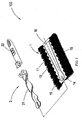
- Fig. 1 is an exploded view of the duster 100according to the first embodiment of the present invention.
- the duster 100 consists of a dusting portion 1 and a handle 2, wherein the handle 2 is formed by the combination of a spiral end 21 and a hand-holding portion 22.
- the dusting portion 1 comprises a hot-meltable nonwoven fabric layer 12, an intermingled yarn layer 11 disposed on the hot-meltable nonwoven fabric layer 12, a smooth nonwoven fabric layer 13 disposed on the intermingled yarn layer 11, and a nonwoven/woven fabric layer 14 disposed on the smooth nonwoven fabric layer 13; wherein the intermingled yarn layer 11 is comprised of a plurality of segmented intermingled yarn.
- Fig. 2B which shows the finished product of the dusting portion 1.
- the hot-meltable nonwoven fabric layer 12, the intermingled yarn layer 11, the smooth nonwoven fabric layer 13, and the nonwoven/woven fabric layer 14 are laminated in this order and a hot-pressing process is performed thereto, such that the hot-meltable nonwoven fabric layer 12, the intermingled yarn layer 11, the smooth nonwoven fabric layer 13, and the nonwoven/woven fabric layer 14 are fused with a semi-closed fusion line 15, leaving an opening 16 to form an elongate pocket.
- the widths of the hot-meltable nonwoven fabric layer 12, the smooth nonwoven fabric layer 13, and the nonwoven/woven fabric layer 14 are less than the width of the intermingled yarn layer 11, and the long sides of the hot-meltable nonwoven fabric layer 12, the smooth nonwoven fabric layer 13, and the nonwoven/woven fabric layer 14 are cut to be wavy or straight to effectively control the extending direction of the segmented intermingled yarn of the intermingled yarn layer 11.
- the plurality of segmented intermingled yarn of the intermingled yarn layer 11 comprises an alternately loose and tight structure.
- the fibers at the loose portions of the plurality of segmented intermingled yarn are capable of capturing more dust, hence the performance of the dusting portion 1 is improved.
- each bundle of segmented intermingled yarn is formed by two strands of yarn twisted in different direction, the each bundle of segmented intermingled yarn is effectively bound so as not to tangle with the other bundles of segmented intermingled yarn.
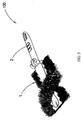
- Figs. 1 and 3 As shown in Fig. 1 , the spiral end 21 of the handle 2 of the duster 100 is inserted into the elongate pocket of the dusting portion 1 through the opening 16. One end of the elongate pocket opposing to the opening 16 is divided into two portions by a fusion line 18, so as to accomodate the fork-shaped front-end of the spiral end 21, thereby making the dusting portion 1 spiral along with the spiral end 21, as shown in Fig. 3 .
- the duster 100 with the spiral dusting portion 1 provides a multi-directional dusting function, and by such a design the dusting portion 1 and the handle 2 can easily engage/disengage with/from each other. Further, the width on the middle portion of the elongate pocket is slightly narrowed to prevent the spiral end 21 of the handle 2 from easily slipping out of the dusting portion 1.
- Fig. 4 is a schematic view of the integral duster 200 according to the second embodiment of the present invention. According to the figure, it can be known that the duster 200 consists of a dusting portion 1' and a handle 3.
- Fig. 5 is a schematic view of the finished product of the dusting portion 1' of the duster 200 according to the second embodiment of the present invention.
- the dusting portion 1' is formed by laminating a hot-meltable nonwoven fabric layer 12', an intermingled yam layer 11', a smooth nonwoven fabric layer 13', and a nonwoven/woven fabric layer 14' in this order then performing a hot-pressing process thereto, wherein the intermingled yarn layer 11' is comprised of a plurality of segmented intermingled yarn.
- the dusting portion 1' undergone hot-pressing comprises fusion lines 15' which combine the hot-meltable nonwoven fabric layer 12', the intermingled yarn layer 11', the smooth nonwoven fabric layer 13', and the nonwoven/woven fabric layer 14' by fusion.
- the fusion lines 15' leave two openings 16' on the dusting portion 1' on the same side and form two juxtaposed-elongate pockets, wherein a slit 17 is further formed between the two elongate pockets so that the dusting portion 1' is easily to be folded.
- the plurality of segmented intermingled yam of the intermingled yarn layer 11' also comprises an alternately loose and tight structure, therefore the performance of the dusting portion 1' is improved; and since each bundle of segmented intermingled yarn is formed by two strands of yam twisted in different direction, the each bundle of segmented intermingled yarn is effectively bound so as not to tangle with the other bundles of segmented intermingled yarn.
- the widths of the hot-meltable nonwoven fabric layer 12', the smooth nonwoven fabric layer 13', and the nonwoven/woven fabric layer 14' are less than the width of the intermingled yarn layer 11', and the long sides of the hot-meltable nonwoven fabric layer 12', the smooth nonwoven fabric layer 13', and the nonwoven/woven fabric layer 14' are cut to be wavy or straight to effectively control the extending direction of the segmented intermingled yam of the intermingled yam layer 11'.
- the handle 3 is fork-shaped and comprises two elongate ends 31.
- the two elongate ends 31 are inserted into the two elongate pockets on the dusting portion 1' through the openings 16 in the direction indicated by the arrow, thereby forming the duster 200.
- the dusting portion 1' and the handle 3 can easily engage/disengage with/from each other.
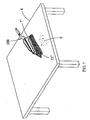
- Fig. 7 shows a schematic view of the use of the duster 200according to the second embodiment of the present invention. It can be seen from the view that the segmented intermingled yarn of the dusting portion 1' of the duster 200 is exposed for capturing the dust 5 on a table 4, and the duster 200 involves the best dusting effect when the angle between the segmented intermingled yarn and the surface of the table is 90 degree.
Landscapes
- Cleaning Implements For Floors, Carpets, Furniture, Walls, And The Like (AREA)
Claims (13)
- Staubbesen (100) bestehend aus einem Staubwischbereich (1) und einem Griff (2), wobei der Griff (2) einen spiralförmigen Abschluss (21) und einen als Handgriff ausgebildeten Abschnitt (22) beinhaltet oder gabelförmig ist und zwei längliche Enden beinhaltet,
wobei der Staubwischbereich (1) beinhaltet:eine heiß schmelzbare nicht-gewebte Textilschicht (12);eine vermischte Fadenschicht (11), die auf der heiß schmelzbaren, nicht-gewebten Textilschicht (12) angeordnet ist und eine Vielzahl von segmentierten, vermischten Fäden aufweist;eine glatte, nicht-gewebte Textilschicht (13), die auf der vermischten Fadenschicht (11) angeordnet ist; undeine nicht-gewebte/gewebte Textilschicht (14), die auf der glatten, nicht-gewebten Textilschicht (13) angeordnet ist;wobei ein Aufnahmeraum zur Aufnahme des Griffes (2) an dem Staubwischbereich (1) angeordnet ist,dadurch gekennzeichnet, dassdie Breite der heiß schmelzbaren, nicht-gewebten Textilschicht (12), der glatten, nicht-gewebten Textilschicht (13) und der nicht-gewebten/gewebten Textilschicht (14) kleiner ist als die der vermischten Fadenschicht (11), so dass die vermischten Fäden des Staubwischbereichs exponiert sind unddass die Längsseiten der heiß schmelzbaren, nicht-gewebten Textilschicht (12), der glatten, nicht-gewebten Textilschicht (13) und der nicht-gewebten/gewebten Textilschicht (14) zugeschnitten sind, um wellenartig oder gerade zu sein, um die Verlaufsrichtung der segmentierten vermischten Fäden der vermischten Fadenschicht (11) effektiv zu kontrollieren. - Staubbesen (100) nach Anspruch 1, wobei jedes Bündel der segmentierten, vermischten Fäden durch zwei Gamstränge ausgebildet ist, die in verschiedene Richtungen verdreht sind.
- Staubbesen (100) nach Anspruch 1, wobei die heiß schmelzbare, nicht-gewebte Textilschicht (12), die vermischte Fadenschicht (11), die glatte, nicht-gewebte Textilschicht (13) und die nicht-gewebte/gewebte Textilschicht (14) in dieser Reihenfolge geschichtet sind und ein Heißpressprozess daran durchgeführt wird, so dass die heiß schmelzbare, nicht-gewebte Textilschicht (12), die vermischte Fadenschicht (11), die glatte, nicht-gewebte Textilschicht (13) und die nicht-gewebte/gewebte Textilschicht (14) in einer halbgeschlossenen Schmelzlinie (15) verschmolzen sind, um den Aufnahmeraum frei zu lassen.
- Staubbesen (100) nach Anspruch 1, wobei der spiralförmige Abschluss (21) des Griffes (2) in den Aufnahmeraum eingefügt wird, so dass der Staubwischbereich (1) zusammen mit dem spiralförmigen Abschluss (21) spiralförmig wird.
- Staubbesen (100) nach Anspruch 1, wobei der Aufnahmeraum für den gabelförmigen Griff aus zwei nebeneinanderstehenden Taschen zur Aufnahme der beiden länglichen Enden des Griffs besteht.
- Staubbesen (100) nach Anspruch 5, wobei ein Schlitz zwischen den beiden Taschen ausgebildet ist, so dass der Staubwischbereich leicht gefaltet werden kann.
- Staubbesen (100) nach Anspruch 1, wobei die segmentierten vermischten Fäden des Staubwischbereichs exponiert sind und der Abstaubeffekt des Staubbesens am Besten ist, wenn der Winkel zwischen den segmentierten vermischten Fäden des Staubwischbereichs und der Oberfläche eines zu reinigenden Gegenstandes 90 Grad beträgt.
- Staubtuch umfassend:eine heiß schmelzbare, nicht-gewebte Textilschicht (12);eine vermischte Fadenschicht (11), die auf der heiß schmelzbaren, nicht-gewebten Textilschicht (12) angeordnet ist und eine Vielzahl von segmentierten, vermischten Fäden aufweist;eine glatte, nicht-gewebte Textilschicht (13), die auf der vermischten Fadenschicht (11) angeordnet ist; undeine nicht-gewebte/gewebte Textilschicht (14), die auf der glatten, nicht-gewebten Textilschicht (13) angeordnet ist;wobei ein Aufnahmeraum zur Aufnahme des Griffes (2) eines Staubbesens (100) an dem Staubtuch angeordnet ist,dadurch gekennzeichnet, dassdie Breite der heiß schmelzbaren, nicht-gewebten Textilschicht (12), der glatten, nicht-gewebten Textilschicht (13) und der nicht-gewebten/gewebten Textilschicht (14) kleiner ist als die der vermischten Fadenschicht (11), so dass die vermischten Fäden des Staubwischbereichs exponiert sind,wobei die Längsseiten der heiß schmelzbaren, nicht-gewebten Textilschicht (12), der glatten, nicht-gewebten Textilschicht (13) und der nicht-gewebten/gewebten Textilschicht (14) zugeschnitten sind, um wellenartig oder gerade zu sein, um die Verlaufsrichtung der segmentierten vermischten Fäden der vermischten Fadenschicht (11) effektiv zu kontrollieren.
- Staubtuch nach Anspruch 8, wobei jedes Bündel der segmentierten, vermischten Fäden durch zwei Garnstränge ausgebildet ist, die in verschiedenen Richtungen verdreht sind.
- Staubtuch nach Anspruch 8, wobei die heiß schmelzbare, nicht-gewebte Textilschicht (12), die vermischte Fadenschicht (11), die glatte, nicht-gewebte Textilschicht (13) und die nicht-gewebte/gewebte Textilschicht (14) in dieser Reihenfolge geschichtet sind und ein Heißpressprozess daran durchgeführt wird, so dass die heiß schmelzbare, nicht-gewebte Textilschicht (12), die vermischte Fadenschicht (11), die glatte, nicht-gewebte Textilschicht (13) und die nicht-gewebte/gewebte Textilschicht(14) in einer halbgeschlossenen Schmelzlinie (15) verschmolzen sind, um einen Aufnahmeraum frei zu lassen.
- Staubtuch nach Anspruch 8, wobei der Aufnahmeraum aus zwei, nebeneinander angeordneten Taschen zur Aufnahme der beiden länglichen Enden des Griffs (2) besteht und die heiß schmelzbare nicht-gewebte Textilschicht (12), die vermischte Fadenschicht (11), die glatte, nicht-gewebte Textilschicht (13) und die nicht-gewebte/gewebte Textilschicht (14) in dieser Reihenfolge geschichtet sind und ein Heißpressprozess daran durchgeführt wird, so dass die heiß schmelzbare, nicht-gewebte Textilschicht (12), die vermischte Fadenschicht (11), die glatte, nicht-gewebte Textilschicht (13) und die nicht-gewebte/gewebte Textilschicht (14) mit Schmelzlinien verschmolzen sind, um die zwei Taschen frei zu lassen.
- Staubtuch nach Anspruch 11, wobei ein Schlitz zwischen den beiden Taschen ausgebildet ist, so dass das Staubtuch leicht gefaltet werden kann.
- Staubtuch nach Anspruch 8, wobei die segmentierten, vermischten Fäden des Staubtuchs exponiert sind und der Abstaubeffekt des Staubtuchs am Besten ist, wenn der Winkel zwischen den segmentierten, vermischten Fäden des Staubtuchs und der Oberfläche eines zu reinigenden Gegenstandes 90 Grad beträgt.
Priority Applications (2)
| Application Number | Priority Date | Filing Date | Title |
|---|---|---|---|
| EP06012174A EP1867268B1 (de) | 2006-06-13 | 2006-06-13 | Staubwedel und zugehöriges Staubtuch |
| AT06012174T ATE514370T1 (de) | 2006-06-13 | 2006-06-13 | Staubwedel und zugehöriges staubtuch |
Applications Claiming Priority (1)
| Application Number | Priority Date | Filing Date | Title |
|---|---|---|---|
| EP06012174A EP1867268B1 (de) | 2006-06-13 | 2006-06-13 | Staubwedel und zugehöriges Staubtuch |
Publications (2)
| Publication Number | Publication Date |
|---|---|
| EP1867268A1 EP1867268A1 (de) | 2007-12-19 |
| EP1867268B1 true EP1867268B1 (de) | 2011-06-29 |
Family
ID=36972739
Family Applications (1)
| Application Number | Title | Priority Date | Filing Date |
|---|---|---|---|
| EP06012174A Not-in-force EP1867268B1 (de) | 2006-06-13 | 2006-06-13 | Staubwedel und zugehöriges Staubtuch |
Country Status (2)
| Country | Link |
|---|---|
| EP (1) | EP1867268B1 (de) |
| AT (1) | ATE514370T1 (de) |
Families Citing this family (2)
| Publication number | Priority date | Publication date | Assignee | Title |
|---|---|---|---|---|
| USD1105679S1 (en) * | 2023-07-07 | 2025-12-09 | Kristine R. Gorinas | Dusting attachment for a broom |
| USD1093793S1 (en) * | 2024-10-31 | 2025-09-16 | Lanhu Brand Management (Hangzhou) Co., Ltd | Dusting tool |
Family Cites Families (3)
| Publication number | Priority date | Publication date | Assignee | Title |
|---|---|---|---|---|
| JP4785369B2 (ja) * | 2004-11-16 | 2011-10-05 | ユニ・チャーム株式会社 | 清掃用物品 |
| DE202004018160U1 (de) * | 2004-11-23 | 2005-04-14 | Oimo Industrial Company Ltd. | Gewölbtes Staubtuch |
| TWI281385B (en) * | 2005-03-10 | 2007-05-21 | Ya-Jin Yang | Duster cleaning tool |
-
2006
- 2006-06-13 EP EP06012174A patent/EP1867268B1/de not_active Not-in-force
- 2006-06-13 AT AT06012174T patent/ATE514370T1/de not_active IP Right Cessation
Also Published As
| Publication number | Publication date |
|---|---|
| EP1867268A1 (de) | 2007-12-19 |
| ATE514370T1 (de) | 2011-07-15 |
Similar Documents
| Publication | Publication Date | Title |
|---|---|---|
| CA2698605C (en) | Disposable cleaning pad | |
| JP5427628B2 (ja) | 清掃用具、清掃体 | |
| US8646144B2 (en) | Cleaning sheet | |
| AU2004318325B2 (en) | Cleaning tool sheet and cleaning tool | |
| AU2009237048B2 (en) | Cleaning sheet and process for producing the same | |
| US7650664B2 (en) | Disposable cleaning pad and handle therefor | |
| EP2308361B1 (de) | Reinigungswerkzeug und Reinigungselement | |
| US7788759B2 (en) | Standing duster article | |
| AU2009247447B2 (en) | Cleaning tool and cleaning element holder | |
| US20110119852A1 (en) | Cleaning tool | |
| EP1867268A1 (de) | Staubwedel und zugehöriges Staubtuch | |
| JP5427627B2 (ja) | 清掃用具、清掃体 | |
| JP2008212429A (ja) | 清掃用具及び清掃体 | |
| US8857006B2 (en) | Cleaning implement and cleaning body |
Legal Events
| Date | Code | Title | Description |
|---|---|---|---|
| PUAI | Public reference made under article 153(3) epc to a published international application that has entered the european phase |
Free format text: ORIGINAL CODE: 0009012 |
|
| AK | Designated contracting states |
Kind code of ref document: A1 Designated state(s): AT BE BG CH CY CZ DE DK EE ES FI FR GB GR HU IE IS IT LI LT LU LV MC NL PL PT RO SE SI SK TR |
|
| AX | Request for extension of the european patent |
Extension state: AL BA HR MK YU |
|
| 17P | Request for examination filed |
Effective date: 20080507 |
|
| AKX | Designation fees paid |
Designated state(s): AT BE BG CH CY CZ DE DK EE ES FI FR GB GR HU IE IS IT LI LT LU LV MC NL PL PT RO SE SI SK TR |
|
| 17Q | First examination report despatched |
Effective date: 20090617 |
|
| GRAP | Despatch of communication of intention to grant a patent |
Free format text: ORIGINAL CODE: EPIDOSNIGR1 |
|
| GRAS | Grant fee paid |
Free format text: ORIGINAL CODE: EPIDOSNIGR3 |
|
| GRAA | (expected) grant |
Free format text: ORIGINAL CODE: 0009210 |
|
| AK | Designated contracting states |
Kind code of ref document: B1 Designated state(s): AT BE BG CH CY CZ DE DK EE ES FI FR GB GR HU IE IS IT LI LT LU LV MC NL PL PT RO SE SI SK TR |
|
| REG | Reference to a national code |
Ref country code: GB Ref legal event code: FG4D |
|
| REG | Reference to a national code |
Ref country code: CH Ref legal event code: EP |
|
| REG | Reference to a national code |
Ref country code: IE Ref legal event code: FG4D |
|
| REG | Reference to a national code |
Ref country code: DE Ref legal event code: R096 Ref document number: 602006022738 Country of ref document: DE Effective date: 20110818 |
|
| REG | Reference to a national code |
Ref country code: NL Ref legal event code: VDEP Effective date: 20110629 |
|
| PG25 | Lapsed in a contracting state [announced via postgrant information from national office to epo] |
Ref country code: LT Free format text: LAPSE BECAUSE OF FAILURE TO SUBMIT A TRANSLATION OF THE DESCRIPTION OR TO PAY THE FEE WITHIN THE PRESCRIBED TIME-LIMIT Effective date: 20110629 Ref country code: SE Free format text: LAPSE BECAUSE OF FAILURE TO SUBMIT A TRANSLATION OF THE DESCRIPTION OR TO PAY THE FEE WITHIN THE PRESCRIBED TIME-LIMIT Effective date: 20110629 |
|
| PG25 | Lapsed in a contracting state [announced via postgrant information from national office to epo] |
Ref country code: AT Free format text: LAPSE BECAUSE OF FAILURE TO SUBMIT A TRANSLATION OF THE DESCRIPTION OR TO PAY THE FEE WITHIN THE PRESCRIBED TIME-LIMIT Effective date: 20110629 Ref country code: LV Free format text: LAPSE BECAUSE OF FAILURE TO SUBMIT A TRANSLATION OF THE DESCRIPTION OR TO PAY THE FEE WITHIN THE PRESCRIBED TIME-LIMIT Effective date: 20110629 Ref country code: FI Free format text: LAPSE BECAUSE OF FAILURE TO SUBMIT A TRANSLATION OF THE DESCRIPTION OR TO PAY THE FEE WITHIN THE PRESCRIBED TIME-LIMIT Effective date: 20110629 Ref country code: GR Free format text: LAPSE BECAUSE OF FAILURE TO SUBMIT A TRANSLATION OF THE DESCRIPTION OR TO PAY THE FEE WITHIN THE PRESCRIBED TIME-LIMIT Effective date: 20110930 Ref country code: SI Free format text: LAPSE BECAUSE OF FAILURE TO SUBMIT A TRANSLATION OF THE DESCRIPTION OR TO PAY THE FEE WITHIN THE PRESCRIBED TIME-LIMIT Effective date: 20110629 |
|
| PG25 | Lapsed in a contracting state [announced via postgrant information from national office to epo] |
Ref country code: BE Free format text: LAPSE BECAUSE OF FAILURE TO SUBMIT A TRANSLATION OF THE DESCRIPTION OR TO PAY THE FEE WITHIN THE PRESCRIBED TIME-LIMIT Effective date: 20110629 |
|
| PG25 | Lapsed in a contracting state [announced via postgrant information from national office to epo] |
Ref country code: IS Free format text: LAPSE BECAUSE OF FAILURE TO SUBMIT A TRANSLATION OF THE DESCRIPTION OR TO PAY THE FEE WITHIN THE PRESCRIBED TIME-LIMIT Effective date: 20111029 Ref country code: EE Free format text: LAPSE BECAUSE OF FAILURE TO SUBMIT A TRANSLATION OF THE DESCRIPTION OR TO PAY THE FEE WITHIN THE PRESCRIBED TIME-LIMIT Effective date: 20110629 Ref country code: NL Free format text: LAPSE BECAUSE OF FAILURE TO SUBMIT A TRANSLATION OF THE DESCRIPTION OR TO PAY THE FEE WITHIN THE PRESCRIBED TIME-LIMIT Effective date: 20110629 Ref country code: CZ Free format text: LAPSE BECAUSE OF FAILURE TO SUBMIT A TRANSLATION OF THE DESCRIPTION OR TO PAY THE FEE WITHIN THE PRESCRIBED TIME-LIMIT Effective date: 20110629 Ref country code: PT Free format text: LAPSE BECAUSE OF FAILURE TO SUBMIT A TRANSLATION OF THE DESCRIPTION OR TO PAY THE FEE WITHIN THE PRESCRIBED TIME-LIMIT Effective date: 20111031 |
|
| PG25 | Lapsed in a contracting state [announced via postgrant information from national office to epo] |
Ref country code: CY Free format text: LAPSE BECAUSE OF FAILURE TO SUBMIT A TRANSLATION OF THE DESCRIPTION OR TO PAY THE FEE WITHIN THE PRESCRIBED TIME-LIMIT Effective date: 20110629 Ref country code: PL Free format text: LAPSE BECAUSE OF FAILURE TO SUBMIT A TRANSLATION OF THE DESCRIPTION OR TO PAY THE FEE WITHIN THE PRESCRIBED TIME-LIMIT Effective date: 20110629 Ref country code: SK Free format text: LAPSE BECAUSE OF FAILURE TO SUBMIT A TRANSLATION OF THE DESCRIPTION OR TO PAY THE FEE WITHIN THE PRESCRIBED TIME-LIMIT Effective date: 20110629 Ref country code: RO Free format text: LAPSE BECAUSE OF FAILURE TO SUBMIT A TRANSLATION OF THE DESCRIPTION OR TO PAY THE FEE WITHIN THE PRESCRIBED TIME-LIMIT Effective date: 20110629 Ref country code: IT Free format text: LAPSE BECAUSE OF FAILURE TO SUBMIT A TRANSLATION OF THE DESCRIPTION OR TO PAY THE FEE WITHIN THE PRESCRIBED TIME-LIMIT Effective date: 20110629 |
|
| PLBE | No opposition filed within time limit |
Free format text: ORIGINAL CODE: 0009261 |
|
| STAA | Information on the status of an ep patent application or granted ep patent |
Free format text: STATUS: NO OPPOSITION FILED WITHIN TIME LIMIT |
|
| 26N | No opposition filed |
Effective date: 20120330 |
|
| PG25 | Lapsed in a contracting state [announced via postgrant information from national office to epo] |
Ref country code: DK Free format text: LAPSE BECAUSE OF FAILURE TO SUBMIT A TRANSLATION OF THE DESCRIPTION OR TO PAY THE FEE WITHIN THE PRESCRIBED TIME-LIMIT Effective date: 20110629 |
|
| REG | Reference to a national code |
Ref country code: DE Ref legal event code: R097 Ref document number: 602006022738 Country of ref document: DE Effective date: 20120330 |
|
| PG25 | Lapsed in a contracting state [announced via postgrant information from national office to epo] |
Ref country code: MC Free format text: LAPSE BECAUSE OF NON-PAYMENT OF DUE FEES Effective date: 20120630 |
|
| REG | Reference to a national code |
Ref country code: CH Ref legal event code: PL |
|
| REG | Reference to a national code |
Ref country code: CH Ref legal event code: PL |
|
| REG | Reference to a national code |
Ref country code: IE Ref legal event code: MM4A |
|
| PG25 | Lapsed in a contracting state [announced via postgrant information from national office to epo] |
Ref country code: ES Free format text: LAPSE BECAUSE OF FAILURE TO SUBMIT A TRANSLATION OF THE DESCRIPTION OR TO PAY THE FEE WITHIN THE PRESCRIBED TIME-LIMIT Effective date: 20111010 Ref country code: CH Free format text: LAPSE BECAUSE OF NON-PAYMENT OF DUE FEES Effective date: 20120630 Ref country code: LI Free format text: LAPSE BECAUSE OF NON-PAYMENT OF DUE FEES Effective date: 20120630 Ref country code: IE Free format text: LAPSE BECAUSE OF NON-PAYMENT OF DUE FEES Effective date: 20120613 |
|
| REG | Reference to a national code |
Ref country code: DE Ref legal event code: R082 Ref document number: 602006022738 Country of ref document: DE Representative=s name: LANGPATENT ANWALTSKANZLEI IP LAW FIRM, DE |
|
| PG25 | Lapsed in a contracting state [announced via postgrant information from national office to epo] |
Ref country code: BG Free format text: LAPSE BECAUSE OF FAILURE TO SUBMIT A TRANSLATION OF THE DESCRIPTION OR TO PAY THE FEE WITHIN THE PRESCRIBED TIME-LIMIT Effective date: 20110929 |
|
| PG25 | Lapsed in a contracting state [announced via postgrant information from national office to epo] |
Ref country code: TR Free format text: LAPSE BECAUSE OF FAILURE TO SUBMIT A TRANSLATION OF THE DESCRIPTION OR TO PAY THE FEE WITHIN THE PRESCRIBED TIME-LIMIT Effective date: 20110629 |
|
| PG25 | Lapsed in a contracting state [announced via postgrant information from national office to epo] |
Ref country code: LU Free format text: LAPSE BECAUSE OF NON-PAYMENT OF DUE FEES Effective date: 20120613 |
|
| PG25 | Lapsed in a contracting state [announced via postgrant information from national office to epo] |
Ref country code: HU Free format text: LAPSE BECAUSE OF FAILURE TO SUBMIT A TRANSLATION OF THE DESCRIPTION OR TO PAY THE FEE WITHIN THE PRESCRIBED TIME-LIMIT Effective date: 20060613 |
|
| PGFP | Annual fee paid to national office [announced via postgrant information from national office to epo] |
Ref country code: GB Payment date: 20140620 Year of fee payment: 9 |
|
| PGFP | Annual fee paid to national office [announced via postgrant information from national office to epo] |
Ref country code: DE Payment date: 20140513 Year of fee payment: 9 |
|
| PGFP | Annual fee paid to national office [announced via postgrant information from national office to epo] |
Ref country code: FR Payment date: 20140617 Year of fee payment: 9 |
|
| REG | Reference to a national code |
Ref country code: DE Ref legal event code: R119 Ref document number: 602006022738 Country of ref document: DE |
|
| GBPC | Gb: european patent ceased through non-payment of renewal fee |
Effective date: 20150613 |
|
| REG | Reference to a national code |
Ref country code: FR Ref legal event code: ST Effective date: 20160229 |
|
| PG25 | Lapsed in a contracting state [announced via postgrant information from national office to epo] |
Ref country code: GB Free format text: LAPSE BECAUSE OF NON-PAYMENT OF DUE FEES Effective date: 20150613 Ref country code: DE Free format text: LAPSE BECAUSE OF NON-PAYMENT OF DUE FEES Effective date: 20160101 |
|
| PG25 | Lapsed in a contracting state [announced via postgrant information from national office to epo] |
Ref country code: FR Free format text: LAPSE BECAUSE OF NON-PAYMENT OF DUE FEES Effective date: 20150630 |