EP1867378B1 - Komprimierbares Filterelement - Google Patents
Komprimierbares Filterelement Download PDFInfo
- Publication number
- EP1867378B1 EP1867378B1 EP07011014A EP07011014A EP1867378B1 EP 1867378 B1 EP1867378 B1 EP 1867378B1 EP 07011014 A EP07011014 A EP 07011014A EP 07011014 A EP07011014 A EP 07011014A EP 1867378 B1 EP1867378 B1 EP 1867378B1
- Authority
- EP
- European Patent Office
- Prior art keywords
- filter element
- element according
- filter
- component
- components
- Prior art date
- Legal status (The legal status is an assumption and is not a legal conclusion. Google has not performed a legal analysis and makes no representation as to the accuracy of the status listed.)
- Active
Links
Images


Classifications
-
- B—PERFORMING OPERATIONS; TRANSPORTING
- B01—PHYSICAL OR CHEMICAL PROCESSES OR APPARATUS IN GENERAL
- B01D—SEPARATION
- B01D46/00—Filters or filtering processes specially modified for separating dispersed particles from gases or vapours
- B01D46/52—Particle separators, e.g. dust precipitators, using filters embodying folded corrugated or wound sheet material
- B01D46/521—Particle separators, e.g. dust precipitators, using filters embodying folded corrugated or wound sheet material using folded, pleated material
-
- B—PERFORMING OPERATIONS; TRANSPORTING
- B01—PHYSICAL OR CHEMICAL PROCESSES OR APPARATUS IN GENERAL
- B01D—SEPARATION
- B01D35/00—Filtering devices having features not specifically covered by groups B01D24/00 - B01D33/00, or for applications not specifically covered by groups B01D24/00 - B01D33/00; Auxiliary devices for filtration; Filter housing constructions
- B01D35/30—Filter housing constructions
- B01D35/305—Filter housing constructions with features related to crash tests or crash safety measures
-
- B—PERFORMING OPERATIONS; TRANSPORTING
- B01—PHYSICAL OR CHEMICAL PROCESSES OR APPARATUS IN GENERAL
- B01D—SEPARATION
- B01D2275/00—Filter media structures for filters specially adapted for separating dispersed particles from gases or vapours
- B01D2275/20—Shape of filtering material
- B01D2275/203—Shapes flexible in their geometry, e.g. bendable, adjustable to a certain size
Definitions
- the invention relates to a filter element according to the preamble of patent claim 1.
- a filter element which has a layered nonwoven fabric, which is strongly densified in some areas.
- a filter element which has a filter material and a support material.
- the US Pat. No. 5,924,445 shows a filter element having a plurality of flow openings.
- a filter element is known, in which a fuel Saugrohrieitung is partially arranged.
- a filter element for a vacuum cleaner made of paper known.
- a filter element is disclosed which comprises a thermoplastic resin as binder material.
- Filter elements of the type mentioned are already known from the prior art and are used in particular in the engine air filtration in motor vehicles, namely in their intake systems, application.
- the known filter elements have as a filter medium paper, which is folded.
- the known filter elements are currently often arranged in crumple zones and thus crash-relevant areas of a motor vehicle.
- the known filter elements due to their compact design and rigid shape! offer a very large resistance to deformation and limit the deformability of the entire intake system. This is particularly critical when a road user, such as a pedestrian, with a body part abuts against a region of the body, under which such a hard component is arranged.
- a generic filter element made of paper is arranged under the body, for example the hood, in an intake system. Then the deformability of the intake system and thus the body by the generic filter element is so severely limited that a significant risk of injury to the road user is given.
- the generic filter elements must be arranged in such a spaced from body components, that a trouble-free deformability of the body and the intake system is ensured.
- the consequence of this are unused space, especially under the hood,
- the invention is therefore based on the object, a filter element of the type mentioned in such a way and further, that this has a sufficiently large filter performance with ease deformability.
- the filter element is characterized in that the distance by at least 20%, preferably by at least 75%, can be reduced.
- a nonwoven fabric allows in a surprisingly simple manner to produce a reversibly deformable filter element, which provides a sufficiently large filter surface.
- the filter performance of a paper can also be ensured by a nonwoven having a specific fold with a lower fold density.
- the pleats of two adjacent folds can be further spaced than those of a filter medium made of paper. So the fold density can be reduced can.
- the further spacing of the folds allows buckling of the folds and thus a problem-free reduction of the distance between the components.
- a nonwoven fabric has a particular elasticity, which allows a reversible deformation of the filter element. This ensures a conditional serviceability of the filter element after deformation by an accident, namely a so-called emergency running property.
- a filter element is specified, which has a problem-free deformability with sufficiently large filter performance.
- the filter medium has folds whose wrinkle faces are facing the components.
- This specific embodiment allows a problem-free connection of the filter medium with the components.
- an adhesive is assigned to the components, in which the pleated end sides dip and thus form a composite with the components.
- the distance between the components can be reduced by at least 20%, preferably by at least 75%. This specific embodiment ensures that a pedestrian who comes with a body part against the body of a motor vehicle, is largely spared injury. The risk of injury is thereby considerably reduced.
- the filter medium has a height h which can be reduced by at least 20%, preferably by at least 75%.
- the components may be made of a hard material and must contribute almost nothing to the compressibility of the entire filter element.
- the components can be made of conventional plastics.
- the components are made of a consolidated nonwoven fabric. As a result, a material-integrated structure of the filter element can be realized.
- the compressibility of the filter element ie its force-displacement behavior, could be adjusted by modifying the nonwoven fabric used. This modification could be realized by using fibers of different flexural stiffness, which could include synthetic fibers with natural fibers in a certain mixing ratio be connected to each other.
- the stiffness of the nonwoven fabric could also be adjusted by different manufacturing methods. For example, by suitable choice of the parameters of a water jet needling, the stiffness of the nonwoven fabric could be adjusted.
- the nonwoven fabric could comprise synthetic fibers or consist entirely of synthetic fibers. It is conceivable that the synthetic fibers are made of polypropylene, polyester or polybutadiene terephthalate.
- the automotive industry requires from a useable filter element in intake systems according to DIN ISO 5011 a very specific filter performance, namely a separation efficiency of more than 98%. According to this standard, a filter element only shows sufficient filter performance if 98% of the test dusts in the air to be filtered are separated in the filter medium.
- a nonwoven fabric comprising synthetic fibers meets these requirements with problem-free deformability. The easy deformability is essentially realized by a relatively wide pleat spacing.
- the filter medium could be made of a thermoplastic nonwoven fabric.
- a thermoplastic nonwoven surprisingly shows a high compressibility in the folded state. Tests have shown that a folded 48 mm high nonwoven fabric, which is urged in the direction of the pleats, is compressible by 28.32 mm at 100 N. At 0, 5 N, 10 N, 20 N and 50 N, the examined nonwoven fabric can be reduced in height by 0, 0.4 mm, 2.76 mm, 9.54 mm and 17.23 mm respectively. The force vector is oriented parallel to the fold backs in this measurement.
- the thermoplastic nonwoven fabric used is a nonwoven fabric made from polyester fibers. The nonwoven fabric has no binder, but the fibers are welded together by thermal consolidation processes. The nonwoven fabric has a basis weight of 230 g / m 2 .
- Nonwovens which have a basis weight of 100 to 500 g / m 2 .
- Nonwovens of this basis weights have a sufficiently high inherent rigidity in order to space two components apart and at the same time provide a sufficiently high filtration capacity.
- nonwoven fabric surprisingly allows the spacing of the components solely by the filter medium, since the nonwoven fabric shows a sufficiently high inherent stiffness due to its fiber structure.
- a nonwoven fabric has a very high tensile strength and thus high stability, even after soaking and subsequent drying in contrast to paper.
- a nonwoven fabric made of synthetic material shows a high temperature stability and is therefore suitable for use in engine compartments of motor vehicles.
- Other stabilizers that support the filter medium in the spacing of the components are not absolutely necessary. As a result, a cost-effective production of the filter element can be realized.
- further stabilizing agents can be provided to set the deformability of the Filterelments defined.
- the folds are provided with predetermined bending points, which cause a defined buckling of the filter medium when force is applied.
- the wrinkles are imprinted contours that specify or initiate a specific buckling behavior of the folds upon application of force to the components.
- the predetermined bending points could be impressed on the filter medium by ultrasonic welding processes. Uitraschaiisch passluie can be particularly fast and cost-effective perform and allow easy area rejuvenation of a filter medium. It is also conceivable to realize embossing of the filter medium solely by Kraftbaufschlagung.
- the pleat backs could include an angle different from 90 ° with the base surfaces of the components.
- the thus inclined pleat backs can then be easily and particularly easily deformed such that the components approach each other.
- two or more folds are connected to each other at defined intervals such that the fold walls or fold flanks lie against one another. Regions of two or more connected folds could be spaced by a defined number of unconnected folds. Thus, for example, all five folds, two folds could be connected together in a very concise way, but not restrictively. As a result, the deformability of the filter element can be adjusted.
- the fold walls could be glued together, welded or positively connected with each other. Bonding produces a very strong bond. A weld can be realized by stiffening the wrinkles. The interlocking bond allows peeling of the pleats from one another under certain circumstances.
- the pleats of two adjacent pleats could be 0.5 to 3 cm apart.
- the selection of the distance from this range has proved to be particularly advantageous in order to provide both a problem-free deformability of the filter medium and on the other hand still a sufficiently large effective filter area available, which is necessary for the engine air filtration.
- Paper filter media can not realize sufficient filter performance, ie no deposition rate required by the automotive industry, and are therefore unsuitable for intake systems.
- At least one component could be made of a material that is harder or more rigid than the filter medium.
- This specific embodiment allows a production of a stable filter element, which protects the filter medium against impact and shock. Furthermore, the filter medium is protected against contamination. Against this background, it is conceivable that at least one component is made of a consolidated nonwoven fabric.
- At least one component could be produced by injection molding. It is conceivable that the components are made of polypropylene or polyamide.
- At least one component could be made foamed. Such a component forms a very good bond with the filter medium, since the foamed material can flow around the folds of the filter medium.
- Polyurethane could be used as the foamed material. This material is easy to process.
- Metals give the filter element high stability and temperature resistance.
- At least one component could have a passage. This ensures that tubes, hoses or other lines for a medium to be filtered can be connected to the filter element.
- the components sandwich a filter medium, wherein the components and the filter medium form the walls of a volume.
- the medium to be filtered through the filter medium namely a wall of the filter element, inflow and filtered exit through the passage.
- a reversal of the flow direction is also conceivable, namely an entry of the unfiltered medium through the passage and exit through the wall.
- the passage could be associated with sealing means which act as locking means.
- This specific embodiment allows the connection of the passage with a hose, a pipe or other conduit, on the one hand, an elastic seal and on the other hand, a frictional bond is produced.
- the sealing means is designed as a sealing lip, which has a projection which can be engaged behind by a counterpart.
- At least one component locking means could be assigned, which are integrally formed with the component and in complementarily formed latching means receiving an air filter housing can be latched. These latching means could protrude from the edge of the component tongue-shaped. This is concretely conceivable that the tongue-shaped locking means are arranged all around running on a component. As a result, the filter element can be latched into an air filter housing of a motor vehicle without the use of further fastening means.
- At least one component could be assigned predetermined breaking means, which space apart the components in addition to the filter medium.
- predetermined breaking means could be designed such that they break with a very specific application of force to the components and ensure a deformability of the filter element.
- the stabilizing elements are arranged between the components. As a result, a spring-in and rebound of the components is possible.
- the stabilizing elements could be designed as coil springs or leaf springs, since These are mechanically very stable and easily adjustable in terms of their spring constants.
- the filter element could be designed as an air filter of a motor vehicle.
- the easy deformability of the filter element according to the invention makes it ideal for the arrangement in a motor vehicle directly under the hood, where usually air filters are positioned.
- a component acts as a cover of the volume in the air filter housing into which the filter element is inserted.
- the component could be assigned at the factory to seal the volume in the air filter housing seals. As a result, a faster assembly process can be realized.
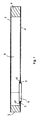
- Fig. 1 shows a first component 1, a second component 2 and a arranged between the components 1, 2, folded filter medium 3.
- the components 1, 2 are spaced by the filter medium 3.
- the filter medium 3 is made of a nonwoven fabric and folded such that a distance between the components 1,2 in their application of force is at least partially reversibly reduced.
- the filter medium 3 acts as a support material due to its inherent rigidity and can space the two components 1, 2 as a single part without further stabilization means.
- the filter medium 3 bounded by the components 1, 2, a volume 9.
- a passage 6 is formed on the lines to the volume 9 are flanged.
- the passage 6 is assigned a ramp-shaped area 10 and a sealing means 7.
- the medium to be filtered enters the volume 9 via the filter medium 3 and is filtered.
- the filtered medium exits via the passage 6 from the volume 9 again.
- a medium to be filtered can also penetrate through the passage 6 into the volume 9 of the filter element and exit via the filter medium 3.
- the volume 9 is limited by the components 1, 2 and the filter medium 3.
- the distance between the two components 1, 2 can be reduced by at least 20%, preferably by at least 75%.
- the filter medium 3 is made of a thermoplastic nonwoven fabric.
- Fig. 2 shows a plan view of a component 2, which is associated with a filter medium 3 made of a thermoplastic nonwoven fabric.
- the filter medium 3 has folds 4, whose fold end faces 4a face the components 1, 2.
- a fold end face 4a faces the component 2 in such a way that the fold end faces 4a are immersed in an adhesive. As a result, a bond between the component 2 and the filter medium 3 is produced.
- the fold backs 5 of two adjacent folds have a spacing of 0.5 to 3 cm.
- the components 1, 2 are made of a material that is harder than the filter medium 3.
- the components 1, 2 are injection-molded and made of polypropylene.
- the filter element shows a wedge-shaped or teardrop-shaped structure.
- the folded filter medium 3 made of a thermoplastic nonwoven fabric is sandwiched between the components 2 and the component 1, not shown.
- Component 2 has a passage 6.
- the component 2 latching means 8 are assigned, which are integrally formed with the component 2 and in complementary thereto formed locking means receiving an air filter housing can be latched.
- the locking means 8 protrude from the edge of the component 2 from tongue-shaped.
- the tongue-shaped locking means 8 are arranged all around running on the component 2. As a result, the filter element can be latched into an air filter housing of a motor vehicle without the use of further fastening means.
- Fig. 3 shows a section of the component 2 according to Fig. 1 , which is connected to the component 1 by a filter medium 3.
- the component 2 has a passage 6, to which a sealing means 7 is assigned.
- the sealing means 7 is designed as a sealing lip made of a thermoplastic ethylene.
- the sealing means 7 has a projection 7a, which acts as a locking means into which a counterpart can engage.
- the counterpart can be designed as a hose, pipe or conduit for a medium to be filtered or filtered.
- the passage 6 is associated with a ramp-shaped region 10, which causes a particularly favorable flow behavior of the medium to be filtered in the relatively narrow volume 9.
- Fig. 4 shows a first component 1, a second component 2 and a arranged between the components 1, 2, folded filter medium 3.
- the components 1, 2 are spaced by the filter medium 3.
- the filter medium 3 is made of a nonwoven fabric and folded such that a distance between the components 1, 2 in their application of force is at least partially reversibly reduced.
- the filter medium 3 acts as a support material due to its inherent rigidity and spaced together with a stabilizing element 11, the two components 1, 2.
- the stabilizing element 11 is formed as a spiral spring and causes compression and rebound of the components 1, 2.
- the coil spring 11 can two approximate each other Components 1, 2 after deformation of the filter medium 3 again to space and spend in their original position.
- the filter medium 3 bounded by the components 1, 2, a volume 9.
- a passage 6 is formed on the lines to the volume 9 are flanged.
- the passage 6 is assigned a ramp-shaped area 10 and a sealing means 7.
Landscapes
- Chemical & Material Sciences (AREA)
- Chemical Kinetics & Catalysis (AREA)
- Filtering Materials (AREA)
- Filtering Of Dispersed Particles In Gases (AREA)
Priority Applications (1)
| Application Number | Priority Date | Filing Date | Title |
|---|---|---|---|
| PL07011014T PL1867378T3 (pl) | 2006-06-14 | 2007-06-05 | Ściśliwy element filtracyjny |
Applications Claiming Priority (2)
| Application Number | Priority Date | Filing Date | Title |
|---|---|---|---|
| DE102006028039 | 2006-06-14 | ||
| DE102006030410A DE102006030410A1 (de) | 2006-06-14 | 2006-06-29 | Komprimierbares Filterelement |
Publications (2)
| Publication Number | Publication Date |
|---|---|
| EP1867378A1 EP1867378A1 (de) | 2007-12-19 |
| EP1867378B1 true EP1867378B1 (de) | 2008-07-09 |
Family
ID=38477268
Family Applications (1)
| Application Number | Title | Priority Date | Filing Date |
|---|---|---|---|
| EP07011014A Active EP1867378B1 (de) | 2006-06-14 | 2007-06-05 | Komprimierbares Filterelement |
Country Status (3)
| Country | Link |
|---|---|
| US (1) | US20080110145A1 (pl) |
| EP (1) | EP1867378B1 (pl) |
| PL (1) | PL1867378T3 (pl) |
Families Citing this family (2)
| Publication number | Priority date | Publication date | Assignee | Title |
|---|---|---|---|---|
| DE102008028834A1 (de) * | 2008-06-19 | 2009-12-31 | Carl Freudenberg Kg | Komprimierbares Filterelement mit zueinander geneigten Endkappen |
| DE202008014270U1 (de) | 2008-10-27 | 2010-03-04 | Mann+Hummel Gmbh | Verformbarer Luftfilter |
Family Cites Families (24)
| Publication number | Priority date | Publication date | Assignee | Title |
|---|---|---|---|---|
| US3417551A (en) * | 1965-11-16 | 1968-12-24 | Ford Motor Co | Air filter |
| US3413782A (en) * | 1966-06-07 | 1968-12-03 | Gem Corp | Automotive air filter |
| US3870495A (en) * | 1972-12-22 | 1975-03-11 | Air Purification Systems Inc | Particulate and/or gas filters and associated filtering equipment to purify air to be breathed by persons in vehicles and/or buildings, and manufacture and installation of these filters |
| DE2901876A1 (de) * | 1979-01-18 | 1980-07-31 | Rommag P Woerwag & Co | Filter fuer staubsauger |
| JPS59162354A (ja) * | 1983-03-08 | 1984-09-13 | Nissan Motor Co Ltd | 燃料フイルタ− |
| US4735720A (en) * | 1986-03-17 | 1988-04-05 | Nelson Industries Inc. | Pleated filter element having improved side seam seal |
| US5320657A (en) * | 1993-04-30 | 1994-06-14 | Dana Corporation | Staggered short pleat air filter |
| USRE37150E1 (en) * | 1994-08-01 | 2001-05-01 | 3M Innovative Properties Company | Occupant air filter for vehicles |
| DE4427817C1 (de) * | 1994-08-05 | 1996-02-29 | Freudenberg Carl Fa | Patronenfilter und Verfahren zur Herstellung eines Patronenfilters |
| US5743927A (en) * | 1996-07-31 | 1998-04-28 | Donaldson Company, Inc. | Air filter element; assembly; and, method |
| DE19634720A1 (de) * | 1996-08-28 | 1998-03-05 | Mann & Hummel Filter | Filterpatrone |
| US5924445A (en) * | 1997-02-20 | 1999-07-20 | Sikorsky Aircraft Corporation | Fuel intake device for fuel systems |
| US5954847A (en) * | 1998-06-23 | 1999-09-21 | Dana Corporation | Radial air filter |
| US6059851A (en) * | 1998-09-03 | 2000-05-09 | Donaldson Company, Inc. | Air cleaner; method and use |
| CA2261919A1 (en) * | 1999-02-09 | 2000-08-09 | Wendell E. Ng-See-Quan | Air filter for vehicles |
| US6638333B2 (en) * | 2001-10-09 | 2003-10-28 | Carrier Corporation | Method and apparatus for assembling an expandable media filter with spacing ribbons |
| US6814773B2 (en) * | 2001-10-09 | 2004-11-09 | Carrier Corporation | Expandable media filter assembly |
| US6726751B2 (en) * | 2001-11-13 | 2004-04-27 | Daniel E. Bause | Accordion-pleated filter material and filter element incorporating same |
| US20040000313A1 (en) * | 2002-06-28 | 2004-01-01 | Kimberly-Clark Worldwide, Inc. | Spunbonded/meltblown/spunbonded laminate face mask |
| US7282077B2 (en) * | 2003-10-24 | 2007-10-16 | Briggs & Stratton Corporation | Air cleaner assembly |
| US7537645B2 (en) * | 2004-03-24 | 2009-05-26 | Advanced Flow Engineering, Inc. | High flow air filtration system for Dodge truck |
| DE102004054245A1 (de) * | 2004-11-09 | 2006-05-18 | Carl Freudenberg Kg | Filterelement und Filter |
| US20060260469A1 (en) * | 2005-05-18 | 2006-11-23 | Advanced Flow Engineering, Inc. | High flow air filtration system |
| DE202005008092U1 (de) * | 2005-05-19 | 2006-09-28 | Mann + Hummel Gmbh | Filterelement |
-
2007
- 2007-06-05 EP EP07011014A patent/EP1867378B1/de active Active
- 2007-06-05 PL PL07011014T patent/PL1867378T3/pl unknown
- 2007-06-13 US US11/762,256 patent/US20080110145A1/en not_active Abandoned
Also Published As
| Publication number | Publication date |
|---|---|
| EP1867378A1 (de) | 2007-12-19 |
| US20080110145A1 (en) | 2008-05-15 |
| PL1867378T3 (pl) | 2009-04-30 |
Similar Documents
| Publication | Publication Date | Title |
|---|---|---|
| EP2135662B2 (de) | Komprimierbares Filterelement mit zueinander geneigten Endkappen | |
| EP1894610B1 (de) | Flexibles Filterelement | |
| DE102009033587B4 (de) | Verstärktes Filterelement und Verfahren zum Verstärken eines Axialfilterkörpers | |
| EP2030665B1 (de) | Filterelement | |
| DE10111318B4 (de) | Filtervorrichtung zur Ausrüstung einer Belüftungs- und/oder Heizungs- und/oder Klimanlage, insbesondere für Kraftfahrzeuge | |
| EP1946811A1 (de) | Filterelement | |
| DE102013019327A1 (de) | Filterelement mit Filterbalg | |
| DE102020113615B4 (de) | Filterelement, Innenraumluftfilter, Filteranordnung und Verwendung eines Filterelements | |
| DE202007011096U1 (de) | Filterelement, Filtergehäuse und Filteranordnung | |
| DE102022125133A1 (de) | Filtervorrichtung, Fahrzeug, Verwendung und Verfahren | |
| DE102019115568A1 (de) | Filterelement und Filtersystem | |
| DE102014016560A1 (de) | Innenraumfilter und Filteranordnung | |
| DE69502386T2 (de) | Filteranordnung zum filtern einer fluidströmung | |
| EP1867378A1 (de) | Komprimierbares Filterelement | |
| DE102008033044B3 (de) | Komprimierbares Filterelement mit einsatzbarem Strömungskanal | |
| DE102016011451A1 (de) | Innenraumluftfilter, eine Filteranordnung und ein Verfahren zum Einbauen eines Innenraumluftfilters | |
| DE102006030410A1 (de) | Komprimierbares Filterelement | |
| EP2070577A1 (de) | Komprimierbares Filterelement mit umklappbarer Dichtlippe | |
| EP4605108A1 (de) | Filterelement, filtervorrichtung, fahrzeug, verwendung und verfahren | |
| DE60132530T2 (de) | Filtervorrichtung für ein Gerät zur Belüftung und/oder zur Beheizung und/oder zur Klimatisierung, insbesondere für ein Kraftfahrzeug und Verwendung solch einer Filtervorrichtung | |
| EP4415852B1 (de) | Filterelement zum filtern von luft und luftfilter | |
| DE102005037313A1 (de) | Filterelement und Anordnung | |
| DE102017221592A1 (de) | Plattenfilterelement für eine Luftfiltereinrichtung | |
| WO2008055486A1 (de) | Filtertasche | |
| DE102022106562A1 (de) | Filterelement und Filtersystem |
Legal Events
| Date | Code | Title | Description |
|---|---|---|---|
| PUAI | Public reference made under article 153(3) epc to a published international application that has entered the european phase |
Free format text: ORIGINAL CODE: 0009012 |
|
| AK | Designated contracting states |
Kind code of ref document: A1 Designated state(s): AT BE BG CH CY CZ DE DK EE ES FI FR GB GR HU IE IS IT LI LT LU LV MC MT NL PL PT RO SE SI SK TR |
|
| AX | Request for extension of the european patent |
Extension state: AL BA HR MK YU |
|
| 17P | Request for examination filed |
Effective date: 20071207 |
|
| GRAP | Despatch of communication of intention to grant a patent |
Free format text: ORIGINAL CODE: EPIDOSNIGR1 |
|
| GRAS | Grant fee paid |
Free format text: ORIGINAL CODE: EPIDOSNIGR3 |
|
| GRAA | (expected) grant |
Free format text: ORIGINAL CODE: 0009210 |
|
| AK | Designated contracting states |
Kind code of ref document: B1 Designated state(s): AT BE BG CH CY CZ DE DK EE ES FI FR GB GR HU IE IS IT LI LT LU LV MC MT NL PL PT RO SE SI SK TR |
|
| REG | Reference to a national code |
Ref country code: GB Ref legal event code: FG4D Free format text: NOT ENGLISH |
|
| REG | Reference to a national code |
Ref country code: CH Ref legal event code: EP |
|
| RIN2 | Information on inventor provided after grant (corrected) |
Inventor name: FELBER, UWE Inventor name: KRUEGER, JOERN-UWE Inventor name: GERHARD, WERNER Inventor name: BEER, BERNHARD Inventor name: WIMMER, RUDOLF Inventor name: MERZ, ROLF DANIEL Inventor name: STAHL, ULRICH |
|
| REF | Corresponds to: |
Ref document number: 502007000042 Country of ref document: DE Date of ref document: 20080821 Kind code of ref document: P |
|
| AKX | Designation fees paid |
Designated state(s): AT BE BG CH CY CZ DE DK EE ES FI FR GB GR HU IE IS IT LI LT LU LV MC MT NL PL PT RO SE SI SK TR |
|
| RAP2 | Party data changed (patent owner data changed or rights of a patent transferred) |
Owner name: BAYERISCHE MOTORENWERKE AKTIENGESELLSCHAFT Owner name: MONTAPLAST GMBH Owner name: CARL FREUDENBERG KG |
|
| REG | Reference to a national code |
Ref country code: IE Ref legal event code: FG4D Free format text: LANGUAGE OF EP DOCUMENT: GERMAN |
|
| NLT2 | Nl: modifications (of names), taken from the european patent patent bulletin |
Owner name: CARL FREUDENBERG KG EN MONTAPLAST GMBH EN BAYERISC Effective date: 20080903 |
|
| NLV1 | Nl: lapsed or annulled due to failure to fulfill the requirements of art. 29p and 29m of the patents act | ||
| PG25 | Lapsed in a contracting state [announced via postgrant information from national office to epo] |
Ref country code: IS Free format text: LAPSE BECAUSE OF FAILURE TO SUBMIT A TRANSLATION OF THE DESCRIPTION OR TO PAY THE FEE WITHIN THE PRESCRIBED TIME-LIMIT Effective date: 20081109 Ref country code: NL Free format text: LAPSE BECAUSE OF FAILURE TO SUBMIT A TRANSLATION OF THE DESCRIPTION OR TO PAY THE FEE WITHIN THE PRESCRIBED TIME-LIMIT Effective date: 20080709 Ref country code: LT Free format text: LAPSE BECAUSE OF FAILURE TO SUBMIT A TRANSLATION OF THE DESCRIPTION OR TO PAY THE FEE WITHIN THE PRESCRIBED TIME-LIMIT Effective date: 20080709 |
|
| PG25 | Lapsed in a contracting state [announced via postgrant information from national office to epo] |
Ref country code: LV Free format text: LAPSE BECAUSE OF FAILURE TO SUBMIT A TRANSLATION OF THE DESCRIPTION OR TO PAY THE FEE WITHIN THE PRESCRIBED TIME-LIMIT Effective date: 20080709 Ref country code: FI Free format text: LAPSE BECAUSE OF FAILURE TO SUBMIT A TRANSLATION OF THE DESCRIPTION OR TO PAY THE FEE WITHIN THE PRESCRIBED TIME-LIMIT Effective date: 20080709 Ref country code: BG Free format text: LAPSE BECAUSE OF FAILURE TO SUBMIT A TRANSLATION OF THE DESCRIPTION OR TO PAY THE FEE WITHIN THE PRESCRIBED TIME-LIMIT Effective date: 20081009 Ref country code: SI Free format text: LAPSE BECAUSE OF FAILURE TO SUBMIT A TRANSLATION OF THE DESCRIPTION OR TO PAY THE FEE WITHIN THE PRESCRIBED TIME-LIMIT Effective date: 20080709 Ref country code: PT Free format text: LAPSE BECAUSE OF FAILURE TO SUBMIT A TRANSLATION OF THE DESCRIPTION OR TO PAY THE FEE WITHIN THE PRESCRIBED TIME-LIMIT Effective date: 20081209 Ref country code: ES Free format text: LAPSE BECAUSE OF FAILURE TO SUBMIT A TRANSLATION OF THE DESCRIPTION OR TO PAY THE FEE WITHIN THE PRESCRIBED TIME-LIMIT Effective date: 20081020 |
|
| REG | Reference to a national code |
Ref country code: IE Ref legal event code: FD4D |
|
| PG25 | Lapsed in a contracting state [announced via postgrant information from national office to epo] |
Ref country code: IE Free format text: LAPSE BECAUSE OF FAILURE TO SUBMIT A TRANSLATION OF THE DESCRIPTION OR TO PAY THE FEE WITHIN THE PRESCRIBED TIME-LIMIT Effective date: 20080709 Ref country code: EE Free format text: LAPSE BECAUSE OF FAILURE TO SUBMIT A TRANSLATION OF THE DESCRIPTION OR TO PAY THE FEE WITHIN THE PRESCRIBED TIME-LIMIT Effective date: 20080709 Ref country code: DK Free format text: LAPSE BECAUSE OF FAILURE TO SUBMIT A TRANSLATION OF THE DESCRIPTION OR TO PAY THE FEE WITHIN THE PRESCRIBED TIME-LIMIT Effective date: 20080709 |
|
| REG | Reference to a national code |
Ref country code: PL Ref legal event code: T3 |
|
| PLBE | No opposition filed within time limit |
Free format text: ORIGINAL CODE: 0009261 |
|
| STAA | Information on the status of an ep patent application or granted ep patent |
Free format text: STATUS: NO OPPOSITION FILED WITHIN TIME LIMIT |
|
| PG25 | Lapsed in a contracting state [announced via postgrant information from national office to epo] |
Ref country code: RO Free format text: LAPSE BECAUSE OF FAILURE TO SUBMIT A TRANSLATION OF THE DESCRIPTION OR TO PAY THE FEE WITHIN THE PRESCRIBED TIME-LIMIT Effective date: 20080709 Ref country code: CZ Free format text: LAPSE BECAUSE OF FAILURE TO SUBMIT A TRANSLATION OF THE DESCRIPTION OR TO PAY THE FEE WITHIN THE PRESCRIBED TIME-LIMIT Effective date: 20080709 |
|
| 26N | No opposition filed |
Effective date: 20090414 |
|
| BERE | Be: lapsed |
Owner name: MONTAPLAST G.M.B.H. Effective date: 20090630 Owner name: CARL FREUDENBERG K.G. Effective date: 20090630 |
|
| PG25 | Lapsed in a contracting state [announced via postgrant information from national office to epo] |
Ref country code: SE Free format text: LAPSE BECAUSE OF FAILURE TO SUBMIT A TRANSLATION OF THE DESCRIPTION OR TO PAY THE FEE WITHIN THE PRESCRIBED TIME-LIMIT Effective date: 20081009 Ref country code: MC Free format text: LAPSE BECAUSE OF NON-PAYMENT OF DUE FEES Effective date: 20090630 |
|
| PG25 | Lapsed in a contracting state [announced via postgrant information from national office to epo] |
Ref country code: BE Free format text: LAPSE BECAUSE OF NON-PAYMENT OF DUE FEES Effective date: 20090630 |
|
| PG25 | Lapsed in a contracting state [announced via postgrant information from national office to epo] |
Ref country code: AT Free format text: LAPSE BECAUSE OF NON-PAYMENT OF DUE FEES Effective date: 20090605 |
|
| PG25 | Lapsed in a contracting state [announced via postgrant information from national office to epo] |
Ref country code: GR Free format text: LAPSE BECAUSE OF FAILURE TO SUBMIT A TRANSLATION OF THE DESCRIPTION OR TO PAY THE FEE WITHIN THE PRESCRIBED TIME-LIMIT Effective date: 20081010 |
|
| PG25 | Lapsed in a contracting state [announced via postgrant information from national office to epo] |
Ref country code: IT Free format text: LAPSE BECAUSE OF NON-PAYMENT OF DUE FEES Effective date: 20100605 |
|
| PG25 | Lapsed in a contracting state [announced via postgrant information from national office to epo] |
Ref country code: LU Free format text: LAPSE BECAUSE OF NON-PAYMENT OF DUE FEES Effective date: 20090605 |
|
| PG25 | Lapsed in a contracting state [announced via postgrant information from national office to epo] |
Ref country code: HU Free format text: LAPSE BECAUSE OF FAILURE TO SUBMIT A TRANSLATION OF THE DESCRIPTION OR TO PAY THE FEE WITHIN THE PRESCRIBED TIME-LIMIT Effective date: 20090110 |
|
| PG25 | Lapsed in a contracting state [announced via postgrant information from national office to epo] |
Ref country code: TR Free format text: LAPSE BECAUSE OF FAILURE TO SUBMIT A TRANSLATION OF THE DESCRIPTION OR TO PAY THE FEE WITHIN THE PRESCRIBED TIME-LIMIT Effective date: 20080709 |
|
| PG25 | Lapsed in a contracting state [announced via postgrant information from national office to epo] |
Ref country code: CY Free format text: LAPSE BECAUSE OF FAILURE TO SUBMIT A TRANSLATION OF THE DESCRIPTION OR TO PAY THE FEE WITHIN THE PRESCRIBED TIME-LIMIT Effective date: 20080709 |
|
| REG | Reference to a national code |
Ref country code: CH Ref legal event code: PL |
|
| GBPC | Gb: european patent ceased through non-payment of renewal fee |
Effective date: 20110605 |
|
| PG25 | Lapsed in a contracting state [announced via postgrant information from national office to epo] |
Ref country code: CH Free format text: LAPSE BECAUSE OF NON-PAYMENT OF DUE FEES Effective date: 20110630 Ref country code: LI Free format text: LAPSE BECAUSE OF NON-PAYMENT OF DUE FEES Effective date: 20110630 |
|
| PG25 | Lapsed in a contracting state [announced via postgrant information from national office to epo] |
Ref country code: GB Free format text: LAPSE BECAUSE OF NON-PAYMENT OF DUE FEES Effective date: 20110605 |
|
| REG | Reference to a national code |
Ref country code: FR Ref legal event code: PLFP Year of fee payment: 9 |
|
| REG | Reference to a national code |
Ref country code: FR Ref legal event code: PLFP Year of fee payment: 10 |
|
| REG | Reference to a national code |
Ref country code: FR Ref legal event code: PLFP Year of fee payment: 11 |
|
| REG | Reference to a national code |
Ref country code: FR Ref legal event code: PLFP Year of fee payment: 12 |
|
| PGFP | Annual fee paid to national office [announced via postgrant information from national office to epo] |
Ref country code: FR Payment date: 20200620 Year of fee payment: 14 |
|
| PGFP | Annual fee paid to national office [announced via postgrant information from national office to epo] |
Ref country code: SK Payment date: 20200522 Year of fee payment: 14 Ref country code: PL Payment date: 20200521 Year of fee payment: 14 |
|
| PGFP | Annual fee paid to national office [announced via postgrant information from national office to epo] |
Ref country code: IT Payment date: 20200630 Year of fee payment: 14 |
|
| REG | Reference to a national code |
Ref country code: SK Ref legal event code: MM4A Ref document number: E 4474 Country of ref document: SK Effective date: 20210605 |
|
| PG25 | Lapsed in a contracting state [announced via postgrant information from national office to epo] |
Ref country code: SK Free format text: LAPSE BECAUSE OF NON-PAYMENT OF DUE FEES Effective date: 20210605 Ref country code: FR Free format text: LAPSE BECAUSE OF NON-PAYMENT OF DUE FEES Effective date: 20210630 |
|
| PG25 | Lapsed in a contracting state [announced via postgrant information from national office to epo] |
Ref country code: PL Free format text: LAPSE BECAUSE OF NON-PAYMENT OF DUE FEES Effective date: 20210605 |
|
| PG25 | Lapsed in a contracting state [announced via postgrant information from national office to epo] |
Ref country code: IT Free format text: LAPSE BECAUSE OF NON-PAYMENT OF DUE FEES Effective date: 20210630 |
|
| P01 | Opt-out of the competence of the unified patent court (upc) registered |
Effective date: 20230904 |
|
| PGFP | Annual fee paid to national office [announced via postgrant information from national office to epo] |
Ref country code: DE Payment date: 20260623 Year of fee payment: 20 |