EP1867554A2 - Actionnement de direction d'une roue directrice d'un chariot de manutention, en particulier une roue arrière d'un chariot de manutention à trois roues - Google Patents
Actionnement de direction d'une roue directrice d'un chariot de manutention, en particulier une roue arrière d'un chariot de manutention à trois roues Download PDFInfo
- Publication number
- EP1867554A2 EP1867554A2 EP07009378A EP07009378A EP1867554A2 EP 1867554 A2 EP1867554 A2 EP 1867554A2 EP 07009378 A EP07009378 A EP 07009378A EP 07009378 A EP07009378 A EP 07009378A EP 1867554 A2 EP1867554 A2 EP 1867554A2
- Authority
- EP
- European Patent Office
- Prior art keywords
- steering
- gear
- drive according
- bearing
- motor
- Prior art date
- Legal status (The legal status is an assumption and is not a legal conclusion. Google has not performed a legal analysis and makes no representation as to the accuracy of the status listed.)
- Granted
Links
Images

Classifications
-
- B—PERFORMING OPERATIONS; TRANSPORTING
- B62—LAND VEHICLES FOR TRAVELLING OTHERWISE THAN ON RAILS
- B62D—MOTOR VEHICLES; TRAILERS
- B62D5/00—Power-assisted or power-driven steering
- B62D5/04—Power-assisted or power-driven steering electrical, e.g. using an electric servo-motor connected to, or forming part of, the steering gear
- B62D5/0418—Electric motor acting on road wheel carriers
-
- B—PERFORMING OPERATIONS; TRANSPORTING
- B62—LAND VEHICLES FOR TRAVELLING OTHERWISE THAN ON RAILS
- B62D—MOTOR VEHICLES; TRAILERS
- B62D7/00—Steering linkage; Stub axles or their mountings
- B62D7/02—Steering linkage; Stub axles or their mountings for pivoted bogies
- B62D7/023—Steering turntables
-
- B—PERFORMING OPERATIONS; TRANSPORTING
- B62—LAND VEHICLES FOR TRAVELLING OTHERWISE THAN ON RAILS
- B62D—MOTOR VEHICLES; TRAILERS
- B62D7/00—Steering linkage; Stub axles or their mountings
- B62D7/02—Steering linkage; Stub axles or their mountings for pivoted bogies
- B62D7/04—Steering linkage; Stub axles or their mountings for pivoted bogies with more than one wheel
-
- F—MECHANICAL ENGINEERING; LIGHTING; HEATING; WEAPONS; BLASTING
- F16—ENGINEERING ELEMENTS AND UNITS; GENERAL MEASURES FOR PRODUCING AND MAINTAINING EFFECTIVE FUNCTIONING OF MACHINES OR INSTALLATIONS; THERMAL INSULATION IN GENERAL
- F16H—GEARING
- F16H1/00—Toothed gearings for conveying rotary motion
- F16H1/28—Toothed gearings for conveying rotary motion with gears having orbital motion
- F16H1/46—Systems consisting of a plurality of gear trains each with orbital gears, i.e. systems having three or more central gears
Definitions
- the invention relates to a steering drive for a steered wheel of a truck according to the preamble of patent claim 1.
- Electric-powered counterbalance trucks with a tricycle landing gear usually have a steered, non-driven rear wheel.
- the rear wheel is usually designed as a twin wheel and mounted with the help of a steering wheel rotatably mounted on the vehicle frame.
- the steering movement is transmitted by means of a rack or a gear on the turntable.
- a steering drive has become known in which the steering motor acts on the steering stool via an eccentric gear.
- the steering stool is mounted on the vehicle frame by means of a four-point bearing.
- the invention has for its object to provide a steering drive for a steered rear wheel of a tricycle truck, which has a better efficiency for the steering gear, a smaller size of the steering motor and the steering gear allows and reduces the cost of storage of the steering rack.
- the steering gear has a coaxial to the steering axis single or multi-stage step planetary gear or planetary coupling gear, and the bearing assembly for the steering rack is disposed within the steering gear.
- the stepped planetary gear or the planetary coupling can be preceded by another planetary gear.
- the steering gear according to the invention allows improved efficiency. Steering motor and steering gear have a small size.
- the arrangement of the steering rack bearing within the planetary gear less expensive bearings can be used. By designing assemblies for steering rack and steering drive assembly costs can be reduced.
- the inner ring is supported by at least one rolling bearing on a central, connected to the steering rack bearing component, while the outer ring is supported on a transmission housing portion.
- rolling bearings in particular tapered roller bearings, are provided.
- the bearing component simultaneously serves as a planetary carrier, wherein the output gear of the transmission is formed by a ring gear provided on the steering wheel.
- the ring gear can be formed in one piece with the steering stool according to a further embodiment of the invention.
- the motor housing and stacked disc-like gear housing sections form a closed drive housing.
- On the steering stool can be arranged a contacting seal, which cooperates sealingly with a facing sealing surface of the facing housing portion.
- sensors and assemblies for controlling the steering motor can be arranged.
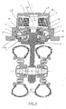
- a frame of a truck is indicated at 40, the example tricycle truck is with steered, non-driven rear wheel.
- the rear wheel is a so-called twin wheel 42, which is mounted in a steering rack 8.
- a generally designated 44 drive housing consists of a cup-like motor housing portion 46 and two disc-like, superimposed Gear housing sections 11, 3, the latter being fixed to the frame 40, which is not shown.
- the steering rack 8 is cup-shaped in the upper region, wherein in the edge of a touching seal 11 a is received, which cooperates sealingly with the facing flat lower surface of the housing portion 3 to prevent the entry of dust and moisture into the drive housing 44.
- motor housing section 46 In the motor housing section 46 is an electric motor 10 with a motor shaft 9, which has an axis 48. On the motor shaft 9, a pinion 6 is arranged or integrally formed therewith. Motor shaft 9 and steering rack 8 are coaxial. The motor shaft 9 is mounted on the housing section 11 by means of a roller bearing 50.
- a planetary coupling gear is arranged with stepped planets 4 a and 4 b, which are coupled together via a coupling shaft 5.
- the planet carrier for the stepped planet 4a is formed by the gear housing section 3.
- the lower stage of the stepped planetary 4a cooperates with a toothing 7 of a ring gear, which is formed by the steering rack 8.
- the pinion 6 cooperates with the larger stage of the stepped planet 4b, while the smaller stage cooperates with the coupling shaft 5.
- the output of the steering gear is formed on the one hand by the mounted on the steering rack bearing component 1 (planet carrier) and on the other by the connected to the fifth wheel ring gear 8.
- FIG. 1 In the illustration of Fig. 1, two tapered roller bearings 2a, 2b can be seen, which are axially spaced and whose inner rings are respectively supported on the bearing component 1 (planet carrier).
- the outer ring of the lower tapered roller bearing 2a supports on the gear housing section 3, and the outer ring of the upper tapered roller bearing 2b is supported on the gear housing section 11 from.
- the storage of the steering rack 8 is within the steering gear shown.
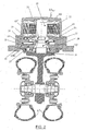
- a drive housing 44a is formed by the motor housing portion 46, in which a motor 30 is arranged with a motor shaft 33 and gear housing sections 24 and 21, which are arranged the last disk-shaped one above the other.
- the drive housing 44a is fixedly connected to the frame 40 via the gear housing section 21, which is not shown in detail.
- the motor shaft 33 has a pinion 32 which cooperates with the larger stage of first stage planet 26.
- the stepped planets 26 are mounted in the housing section 24, which is therefore planetary carrier.
- the smaller stage of the stepped planetary gears 26 is coupled via a connecting shaft 25 to the larger stage of second stepped planetary gears 22.
- the stepped planets 22 are mounted in the housing section 21, which is therefore a planetary carrier.
- the smaller stage of the stepped planetary gears 22 meshes with a ring gear 27 which is formed inside the steering rack 31.
- a pin 20 Coaxially with the steering rack 31, a pin 20 is connected, which has a larger diameter portion near the steering rack 31 and a in A first rolling bearing is formed as a tapered roller bearing and is supported on the pin 20 in the larger diameter portion, and a second tapered roller bearing 29 is supported on the smaller diameter portion of the pin 20, wherein both tapered roller bearings 28, 29 are axially spaced.
- the pin 20, the motor shaft 33 and the steering rack 31 are coaxial as well as the illustrated two-stage stepped planetary gear.
- the output of the steering gear shown is via the ring gear 27th
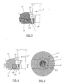
- Fig. 3 a modified compared to FIG. 1 feature is shown.
- the gear housing portion of FIG. 1 is formed by two superimposed portions 35, 36, wherein the roller bearing 50 between motor shaft 9 and housing portion 35 is arranged, while the rolling bearing 2b between the housing portion 36 and the associated portion of the support member 1 and planet carrier is arranged ,
- the housing portion 36 has for this purpose a shoulder 52 on which the outer ring of the tapered roller bearing 2b is supported, while the planet carrier 1, a spring ring 54 provides for the axial securing.
- a bearing ring 38 which sits in a recess of the housing section 37, is arranged on the housing section 37, which corresponds to the housing section 11 according to FIG. 1.
- the bearing ring takes over the support function for the tapered roller bearing 2b, which is taken over in Fig. 3 from the housing portion 36.
- the bearing ring 38 thus also has a shoulder 60 which axially secures the rolling bearing 2b.
- the bearing ring 38 is secured by tangentially arranged pins 62, 64. In this way, the bearing ring 38 can be mounted in a simple manner on the housing portion 37 and disassembled from it.
- a similar steering drive is shown as in Fig. 1, but with a single wheel is steered. Therefore, the structure of the transmission and the interaction with the steering motor will not be discussed further.
- the peculiarity in Fig. 6 is that a shaft 123 of the steering motor is hollow and a sensor shaft 122 is passed. At the lower end, the sensor shaft is rotatably connected to the planet carrier 1 (FIG. With the upper end of the sensor shaft 122 cooperates with a rotation angle sensor 120 which is mounted on the housing 46 of the steering motor.
- the steering angle sensor 120 measures the steering angle redundantly to the steering angle detection in the steering motor.
- a redundant steering angle sensor is also possible with an incremental sensor 124 having a contour on a connected to the steering rack 8 component, for. B. a toothing 125, scans.
Landscapes
- Engineering & Computer Science (AREA)
- Chemical & Material Sciences (AREA)
- Combustion & Propulsion (AREA)
- Transportation (AREA)
- Mechanical Engineering (AREA)
- Power Steering Mechanism (AREA)
- Retarders (AREA)
- Arrangement Or Mounting Of Propulsion Units For Vehicles (AREA)
- Steering-Linkage Mechanisms And Four-Wheel Steering (AREA)
- Automatic Cycles, And Cycles In General (AREA)
Applications Claiming Priority (1)
| Application Number | Priority Date | Filing Date | Title |
|---|---|---|---|
| DE102006027369A DE102006027369A1 (de) | 2006-06-13 | 2006-06-13 | Lenkantrieb für ein gelenktes Rad eines Flurförderzeugs, insbesondere eines Hinterrades eines Dreirad-Flurförderzeugs |
Publications (3)
| Publication Number | Publication Date |
|---|---|
| EP1867554A2 true EP1867554A2 (fr) | 2007-12-19 |
| EP1867554A3 EP1867554A3 (fr) | 2008-10-22 |
| EP1867554B1 EP1867554B1 (fr) | 2010-07-28 |
Family
ID=38480510
Family Applications (1)
| Application Number | Title | Priority Date | Filing Date |
|---|---|---|---|
| EP07009378A Active EP1867554B1 (fr) | 2006-06-13 | 2007-05-10 | Actionnement de direction d'une roue directrice d'un chariot de manutention, en particulier une roue arrière d'un chariot de manutention à trois roues |
Country Status (4)
| Country | Link |
|---|---|
| US (1) | US7669684B2 (fr) |
| EP (1) | EP1867554B1 (fr) |
| CN (1) | CN101088827B (fr) |
| DE (2) | DE102006027369A1 (fr) |
Cited By (1)
| Publication number | Priority date | Publication date | Assignee | Title |
|---|---|---|---|---|
| EP1880923A3 (fr) * | 2006-07-22 | 2010-06-16 | Jungheinrich Aktiengesellschaft | Actionnement de direction pour une roue d'un chariot de manutention avec un dispositif destiné à la détection de l'angle actuel de la roue dirigée |
Families Citing this family (17)
| Publication number | Priority date | Publication date | Assignee | Title |
|---|---|---|---|---|
| WO2005077695A1 (fr) * | 2004-02-11 | 2005-08-25 | Zf Friedrichshafen Ag | Entrainement de direction et de roue pour chariot de manutention |
| DE102006029283B4 (de) * | 2006-06-23 | 2008-10-02 | Kordel Antriebstechnik Gmbh | Lenkantrieb für Flurförderfahrzeug |
| DE102007017821A1 (de) * | 2007-04-16 | 2008-10-23 | Liebherr-Werk Biberach Gmbh | Lastkraftwagen |
| DE102010015713A1 (de) * | 2010-04-21 | 2011-10-27 | Schaeffler Technologies Gmbh & Co. Kg | Bewegbares System |
| DE102010029611A1 (de) * | 2010-06-02 | 2011-12-08 | Zf Friedrichshafen Ag | Lenkbare Antriebsanordnung für ein deichselgeführtes Flurförderzeug |
| DE102010030360A1 (de) * | 2010-06-22 | 2011-12-22 | Zf Friedrichshafen Ag | Lenkbare Antriebsanordnung für ein Flurförderzeug |
| ES2489341B1 (es) * | 2012-09-07 | 2015-03-17 | Microelectronica Maser, S.L. | Sistema de direccion asistida para vehiculos |
| TWI481162B (zh) * | 2012-10-16 | 2015-04-11 | Yung Sung Huang | Double motor drive device and its internal variable speed double motor and clutch deceleration drive device |
| DE102013200388A1 (de) * | 2013-01-14 | 2014-07-17 | Zf Friedrichshafen Ag | Antrieb für ein Flurförderzeug mit Lenkunterstützung |
| DE102013206802A1 (de) * | 2013-04-16 | 2014-10-16 | Zf Friedrichshafen Ag | Lageranordnung für einen Fahrantrieb für ein Flurförderfahrzeug |
| DE102013107052B4 (de) | 2013-07-04 | 2022-04-28 | Linde Material Handling Gmbh | Lenkachse eines Flurförderzeugs |
| US10399437B2 (en) | 2016-09-06 | 2019-09-03 | Joy Global Underground Mining Llc | Coupled compound planetary transmission for a wheel unit |
| CN110171472B (zh) * | 2019-07-11 | 2023-07-07 | 吉林大学 | 一种双模式后轮主动转向装置 |
| TWI755737B (zh) * | 2020-05-22 | 2022-02-21 | 新加坡商普拉希斯國際有限公司 | 具高扭力體積比之輪轂電機 |
| DE102021213067A1 (de) | 2021-11-22 | 2023-05-25 | Zf Friedrichshafen Ag | Lenkantrieb für eine Lenkachse eines lenkbaren Fahrzeugs, Lenkachse und Flurförderzeug |
| DE102021213063B4 (de) | 2021-11-22 | 2023-08-03 | Zf Friedrichshafen Ag | Lenkantrieb für eine Lenkachse eines lenkbaren Fahrzeugs, Lenkachse und Flurförderzeug |
| DE102022210114A1 (de) * | 2022-09-26 | 2024-03-28 | Zf Friedrichshafen Ag | Lenkanordnung mit mehrstufigen Planetengetriebe für ein Flurförderfahrzeug sowie Flurförderfahrzeug mit der Lenkanordnung |
Citations (3)
| Publication number | Priority date | Publication date | Assignee | Title |
|---|---|---|---|---|
| EP0157317A2 (fr) | 1984-04-04 | 1985-10-09 | Fried. Krupp Gesellschaft mit beschränkter Haftung | Procédé et dispositif pour la purification biologique aérobie d'eau résiduaire |
| DE19911458A1 (de) | 1998-03-19 | 1999-10-14 | Linde Ag | Lenkantrieb für Flurförderzeuge |
| DE10113775A1 (de) | 2001-03-21 | 2002-09-26 | Linde Ag | Lenkantrieb mit einem Lenkmotor und einem Lenkgetriebe |
Family Cites Families (13)
| Publication number | Priority date | Publication date | Assignee | Title |
|---|---|---|---|---|
| DE4421428C1 (de) * | 1994-06-18 | 1995-07-27 | Fichtel & Sachs Ag | Mit einem Elektromotor zu einer Baueinheit verbindbares Planetengetriebe |
| US6145611A (en) * | 1997-12-11 | 2000-11-14 | Haddad, Sr.; Albert G. | Computerizable robotic automated bogie |
| DE19904552A1 (de) * | 1998-03-19 | 1999-09-23 | Linde Ag | Radantrieb für Flurförderzeuge |
| DE19932586A1 (de) * | 1999-07-13 | 2001-04-12 | Zahnradfabrik Friedrichshafen | Achse mit einer unterhalb der Radachse angeordneten Achsbrücke |
| JP3995412B2 (ja) * | 2000-12-25 | 2007-10-24 | Tcm株式会社 | 横行システムを持った作業車両 |
| DE20206821U1 (de) * | 2002-04-29 | 2003-09-11 | Liebherr-Werk Biberach GmbH, 88400 Biberach | Fahrantrieb für Lastkraftwagen |
| US6852061B2 (en) * | 2002-09-30 | 2005-02-08 | Benjamin Warren Schoon | Planetary gearbox with integral electric motor and steering means. |
| DE10260001A1 (de) * | 2002-12-20 | 2004-07-08 | Zf Friedrichshafen Ag | Axiale Sicherung der Radlagerung für deichselgeführte Fahrzeuge |
| DE10260003A1 (de) * | 2002-12-20 | 2004-07-08 | Zf Friedrichshafen Ag | Radnabenantrieb |
| DE102004006722A1 (de) * | 2004-02-11 | 2005-09-01 | Zf Friedrichshafen Ag | Lenk- und Radantrieb für ein Flurförderzeug |
| US6974399B2 (en) * | 2004-02-11 | 2005-12-13 | Chiu-Hsiang Lo | Hub motor mechanism |
| DE102006002485A1 (de) * | 2006-01-17 | 2007-09-06 | Jungheinrich Ag | Antriebs- und Lenkeinheit für ein Rad eines Flurförderzeugs |
| DE102006023577A1 (de) * | 2006-05-19 | 2007-11-22 | Jungheinrich Ag | Radnabenantrieb für Flurförderzeuge |
-
2006
- 2006-06-13 DE DE102006027369A patent/DE102006027369A1/de not_active Withdrawn
-
2007
- 2007-05-10 DE DE502007004535T patent/DE502007004535D1/de active Active
- 2007-05-10 EP EP07009378A patent/EP1867554B1/fr active Active
- 2007-05-31 US US11/755,958 patent/US7669684B2/en not_active Expired - Fee Related
- 2007-06-13 CN CN2007101103927A patent/CN101088827B/zh active Active
Patent Citations (3)
| Publication number | Priority date | Publication date | Assignee | Title |
|---|---|---|---|---|
| EP0157317A2 (fr) | 1984-04-04 | 1985-10-09 | Fried. Krupp Gesellschaft mit beschränkter Haftung | Procédé et dispositif pour la purification biologique aérobie d'eau résiduaire |
| DE19911458A1 (de) | 1998-03-19 | 1999-10-14 | Linde Ag | Lenkantrieb für Flurförderzeuge |
| DE10113775A1 (de) | 2001-03-21 | 2002-09-26 | Linde Ag | Lenkantrieb mit einem Lenkmotor und einem Lenkgetriebe |
Cited By (1)
| Publication number | Priority date | Publication date | Assignee | Title |
|---|---|---|---|---|
| EP1880923A3 (fr) * | 2006-07-22 | 2010-06-16 | Jungheinrich Aktiengesellschaft | Actionnement de direction pour une roue d'un chariot de manutention avec un dispositif destiné à la détection de l'angle actuel de la roue dirigée |
Also Published As
| Publication number | Publication date |
|---|---|
| CN101088827A (zh) | 2007-12-19 |
| US20080004148A1 (en) | 2008-01-03 |
| DE102006027369A1 (de) | 2007-12-27 |
| DE502007004535D1 (de) | 2010-09-09 |
| US7669684B2 (en) | 2010-03-02 |
| EP1867554B1 (fr) | 2010-07-28 |
| CN101088827B (zh) | 2012-05-30 |
| EP1867554A3 (fr) | 2008-10-22 |
Similar Documents
| Publication | Publication Date | Title |
|---|---|---|
| EP1867554B1 (fr) | Actionnement de direction d'une roue directrice d'un chariot de manutention, en particulier une roue arrière d'un chariot de manutention à trois roues | |
| EP2991887B1 (fr) | Mecanisme de direction | |
| EP1808323B1 (fr) | Unité d'entraînement et d'orientation d'une roue de chariot élévateur | |
| EP1857317A1 (fr) | Moyeu de roue pour chariots de manutention | |
| WO2005054035A1 (fr) | Direction a superposition pour un vehicule | |
| DE102007035010A1 (de) | Lenkeinheit für ein Rad eines Flurförderzeugs | |
| EP1870314A1 (fr) | Unité de direction électrique pour un véhicule de manutention | |
| DE102017209563A1 (de) | Loslager, Lenkgetriebe und Lenksystem | |
| EP1268256A1 (fr) | Actionneur destine a un systeme de direction de vehicule | |
| EP3544878A1 (fr) | Mécanisme de direction et système de direction | |
| DE10328651A1 (de) | Antriebseinheit mit einem Drehschemel, einem Fahrmotor und einem Lenkmotor | |
| EP1334295B1 (fr) | Differentiel destine a l'entrainement d'axe d'un vehicule | |
| EP1946952A1 (fr) | Unité d'entraînement pour un chariot de manutention | |
| DE102016121412A1 (de) | Festlager und Lenkgetriebe | |
| EP3914502B1 (fr) | Ensemble palier | |
| WO2019048123A1 (fr) | Palier fixe pour un mécanisme de direction et procédé pour fabriquer le palier fixe | |
| EP1694550B1 (fr) | Systeme de direction | |
| EP1502799B1 (fr) | Entraînement de moyeu de roue | |
| DE102004001701A1 (de) | Antriebseinheit für ein Flurförderzeug mit Drehschemellenkung | |
| EP2562058B1 (fr) | Dispositif d'appui monté de manière modulaire pour un semi-remorque et semi-remorque doté d'un tel dispositif d'appui | |
| DE102010002569A1 (de) | Lenkgetriebe und damit ausgestattete Servolenkung | |
| DE102017207708A1 (de) | Festlager, Lenkgetriebe und Lenksystem | |
| EP1717128B1 (fr) | Direction assistée pour un véhicule avec un ensemble vis et écrou à billes | |
| DE102009056356A1 (de) | Servolenkung | |
| EP1913289B1 (fr) | Differentiel sans carter |
Legal Events
| Date | Code | Title | Description |
|---|---|---|---|
| PUAI | Public reference made under article 153(3) epc to a published international application that has entered the european phase |
Free format text: ORIGINAL CODE: 0009012 |
|
| AK | Designated contracting states |
Kind code of ref document: A2 Designated state(s): AT BE BG CH CY CZ DE DK EE ES FI FR GB GR HU IE IS IT LI LT LU LV MC MT NL PL PT RO SE SI SK TR |
|
| AX | Request for extension of the european patent |
Extension state: AL BA HR MK YU |
|
| PUAL | Search report despatched |
Free format text: ORIGINAL CODE: 0009013 |
|
| AK | Designated contracting states |
Kind code of ref document: A3 Designated state(s): AT BE BG CH CY CZ DE DK EE ES FI FR GB GR HU IE IS IT LI LT LU LV MC MT NL PL PT RO SE SI SK TR |
|
| AX | Request for extension of the european patent |
Extension state: AL BA HR MK RS |
|
| 17P | Request for examination filed |
Effective date: 20090206 |
|
| AKX | Designation fees paid |
Designated state(s): DE FR GB IT SE |
|
| 17Q | First examination report despatched |
Effective date: 20090703 |
|
| GRAP | Despatch of communication of intention to grant a patent |
Free format text: ORIGINAL CODE: EPIDOSNIGR1 |
|
| GRAS | Grant fee paid |
Free format text: ORIGINAL CODE: EPIDOSNIGR3 |
|
| GRAA | (expected) grant |
Free format text: ORIGINAL CODE: 0009210 |
|
| RAP1 | Party data changed (applicant data changed or rights of an application transferred) |
Owner name: JUNGHEINRICH AKTIENGESELLSCHAFT |
|
| AK | Designated contracting states |
Kind code of ref document: B1 Designated state(s): DE FR GB IT SE |
|
| REG | Reference to a national code |
Ref country code: GB Ref legal event code: FG4D Free format text: NOT ENGLISH |
|
| REF | Corresponds to: |
Ref document number: 502007004535 Country of ref document: DE Date of ref document: 20100909 Kind code of ref document: P |
|
| REG | Reference to a national code |
Ref country code: SE Ref legal event code: TRGR |
|
| PLBE | No opposition filed within time limit |
Free format text: ORIGINAL CODE: 0009261 |
|
| STAA | Information on the status of an ep patent application or granted ep patent |
Free format text: STATUS: NO OPPOSITION FILED WITHIN TIME LIMIT |
|
| 26N | No opposition filed |
Effective date: 20110429 |
|
| REG | Reference to a national code |
Ref country code: DE Ref legal event code: R097 Ref document number: 502007004535 Country of ref document: DE Effective date: 20110429 |
|
| PGFP | Annual fee paid to national office [announced via postgrant information from national office to epo] |
Ref country code: SE Payment date: 20150528 Year of fee payment: 9 Ref country code: GB Payment date: 20150529 Year of fee payment: 9 |
|
| REG | Reference to a national code |
Ref country code: FR Ref legal event code: PLFP Year of fee payment: 10 |
|
| PGFP | Annual fee paid to national office [announced via postgrant information from national office to epo] |
Ref country code: IT Payment date: 20160523 Year of fee payment: 10 |
|
| GBPC | Gb: european patent ceased through non-payment of renewal fee |
Effective date: 20160510 |
|
| PG25 | Lapsed in a contracting state [announced via postgrant information from national office to epo] |
Ref country code: SE Free format text: LAPSE BECAUSE OF NON-PAYMENT OF DUE FEES Effective date: 20160511 |
|
| REG | Reference to a national code |
Ref country code: FR Ref legal event code: PLFP Year of fee payment: 11 |
|
| PG25 | Lapsed in a contracting state [announced via postgrant information from national office to epo] |
Ref country code: GB Free format text: LAPSE BECAUSE OF NON-PAYMENT OF DUE FEES Effective date: 20160510 |
|
| REG | Reference to a national code |
Ref country code: FR Ref legal event code: PLFP Year of fee payment: 12 |
|
| PG25 | Lapsed in a contracting state [announced via postgrant information from national office to epo] |
Ref country code: IT Free format text: LAPSE BECAUSE OF NON-PAYMENT OF DUE FEES Effective date: 20170510 |
|
| PGFP | Annual fee paid to national office [announced via postgrant information from national office to epo] |
Ref country code: DE Payment date: 20250519 Year of fee payment: 19 |
|
| PGFP | Annual fee paid to national office [announced via postgrant information from national office to epo] |
Ref country code: FR Payment date: 20250523 Year of fee payment: 19 |