EP1867564A1 - Méthode et dispositif pour produire flottabilité - Google Patents
Méthode et dispositif pour produire flottabilité Download PDFInfo
- Publication number
- EP1867564A1 EP1867564A1 EP06255294A EP06255294A EP1867564A1 EP 1867564 A1 EP1867564 A1 EP 1867564A1 EP 06255294 A EP06255294 A EP 06255294A EP 06255294 A EP06255294 A EP 06255294A EP 1867564 A1 EP1867564 A1 EP 1867564A1
- Authority
- EP
- European Patent Office
- Prior art keywords
- fluid
- container
- buoyant
- buoyant fluid
- void
- Prior art date
- Legal status (The legal status is an assumption and is not a legal conclusion. Google has not performed a legal analysis and makes no representation as to the accuracy of the status listed.)
- Granted
Links
Images
Classifications
-
- B—PERFORMING OPERATIONS; TRANSPORTING
- B63—SHIPS OR OTHER WATERBORNE VESSELS; RELATED EQUIPMENT
- B63C—LAUNCHING, HAULING-OUT, OR DRY-DOCKING OF VESSELS; LIFE-SAVING IN WATER; EQUIPMENT FOR DWELLING OR WORKING UNDER WATER; MEANS FOR SALVAGING OR SEARCHING FOR UNDERWATER OBJECTS
- B63C7/00—Salvaging of disabled, stranded, or sunken vessels; Salvaging of vessel parts or furnishings, e.g. of safes; Salvaging of other underwater objects
- B63C7/06—Salvaging of disabled, stranded, or sunken vessels; Salvaging of vessel parts or furnishings, e.g. of safes; Salvaging of other underwater objects in which lifting action is generated in or adjacent to vessels or objects
- B63C7/10—Salvaging of disabled, stranded, or sunken vessels; Salvaging of vessel parts or furnishings, e.g. of safes; Salvaging of other underwater objects in which lifting action is generated in or adjacent to vessels or objects using inflatable floats external to vessels or objects
Definitions
- This invention relates to a fluid, method and apparatus for providing buoyancy, particularly for moving heavy objects underwater.
- Buoyancy techniques are well known and frequently applied for the movement or retrieval of structures underwater. In general, they comprise a container or bag that is attached to the structure that needs to be moved together with a gas which is used to fill or partially fill the container exerting a buoyant force on the structure allowing it to be lifted.
- An alternative approach involves the construction of rigid buoyancy elements using syntactic materials which are weighted. These are affixed to the structure and the weights removed by, for instance, a remote operating vehicle from the buoyancy elements.
- This approach has the disadvantage that once released of their weights, the buoyancy elements exert a sudden upward force which can be difficult to control and could cause damage to subsea equipment, such as ROVs, and personnel.
- the weight of the structure to be lifted is determined and complex calculations performed so that a suitable amount of buoyancy is provided.
- buoyancy elements must be returned to the surface when structures of different weights need to be lifted.
- a buoyant fluid comprising a liquid and a plurality of rigid containers, the rigid containers each having a sealed void containing a gas.
- the buoyant fluid has a specific gravity of less than 0.78g/cm 3 , more preferably less than 0.70g/cm 3 , even more preferably less than 0.65g/cm 3 , especially less than below 0.60g/cm 3 and more especially less than 0.56g/cm 3 .
- the rigid containers may be between 5 microns and 5mm in diameter, preferably between 10 microns and 500 micron in diameter and more preferably between 20 micron and 200 micron in diameter.
- Rigid in this context means that the rigid containers are incompressible at the pressures found in underwater environments.
- the rigid containers are microspheres.
- the buoyant fluid may comprise an oil (preferably low toxicity) such as a hydrocarbon, an aliphatic oil, poly alpha olefin, alkyl ester or vegetable oil that is a triglyceride such as one having the structure: where R 1 , R 2 , and R 3 are hydrocarbon chains typically with a chain length of between C 12 and C 22 to give a range of fatty acids and between zero to three double bonds in the hydrocarbon chain length. Most typically such materials are derived from nature as vegetable oils although synthetic alternatives maybe made.
- an oil preferably low toxicity
- the oil is biodegradable.
- the inherent environmental risk that some liquid therein may leak is not a significant concern because biodegradable oils may be used, such as vegetable oil, which would not be a concern to wildlife in the unlikely event of a leak.
- the liquid may also comprise a viscosifying agent such as organophilic clay, dispersed silica, long chain polymeric materials, surfactants or mixtures of the aforesaid agents.
- a viscosifying agent such as organophilic clay, dispersed silica, long chain polymeric materials, surfactants or mixtures of the aforesaid agents.
- the buoyant fluid exhibits viscoelastic and or rheological properties.
- the viscosity, as measured on a Brookfield type viscometer, of the buoyant fluid can optionally be between 10,000 and 100,000 centipoise, preferably between 20,000 and 100,000 centipoise, more preferably between 40,000 and 80,000 centipoise.
- the viscosity as measured on a Brookfield type viscometer, of the buoyant fluid can be between 500 and 10,000 centipoise, preferably between 1,000 and 5,000 centipoise, more preferably between 2,000 and 3,000 centipoise.
- the buoyant fluid is an incompressible fluid.
- the buoyant fluid may be used to displace water in subsea structures thereby generating a buoyant force.
- the buoyant fluid can be pumped into vessels, structures, or bags rendering them buoyant or partially buoyant. This can be done prior to installation of subsea components, during installation of subsea structures or as part of a process of recovery of subsea structures.
- a method of controlling the buoyancy of a structure comprising, in any order:
- the buoyant fluid comprises a plurality of rigid containers, the rigid containers each having a sealed void containing a gas.
- the buoyant fluid according to the second aspect of the invention is the buoyant fluid according to the first aspect of the invention.
- a method of controlling the buoyancy of a structure comprising, in any order:
- an advantage of embodiments of the present invention is that in use the amount of buoyant fluid in the first container may be increased or decreased as appropriate to further control the buoyancy.
- the buoyant fluid is of a viscosity such that it is flowable and is thus removable by pumping from the first container to control the buoyancy of the structure.
- the buoyant fluid does not solidify after it enters the first container.
- the immersion fluid is water, especially sea water.
- the buoyant fluid may also be added to or removed from the first container before it is immersed in the immersion fluid.
- the buoyant fluid substantially comprises liquid, as well as any rigid containers.
- the gas in each rigid container may be air, nitrogen, argon or another gas sufficient to achieve a low bulk density.
- the buoyant fluid is an incompressible fluid.
- the buoyant fluid may be recovered after use and re-used in a method as described herein.
- An advantage of embodiments of the present invention is that the incompressible fluid does not undergo a volume change when the depth and therefore the pressure of the first container is varied. Consequently, the first container of embodiments of the present invention will not accelerate as its depth varies and so greater control of the structure is afforded.
- an apparatus to control the buoyancy of a structure comprising:
- an apparatus to control the buoyancy of a structure comprising:
- said first void is defined within a bladder.
- a second void is defined between the bladder and the first container.
- a first valve is provided to communicate with the first void.
- the first valve is arranged at said aperture to allow injection or removal of the buoyant fluid into and out of the first container.
- a second valve is provided to communicate with the second void.
- the bladder is preferably flexible so that the volume of the first and second voids can vary although the sum of their volumes typically remains constant.
- the apparatus may comprise a supply container which, in use, contains a buoyant fluid.
- a buoyant fluid is the buoyant fluid described herein with respect to earlier aspects of the invention.
- the supply container is typically connected to the first container via a line (preferably flexible), the line suitable to transfer buoyant fluid between the first container and the supply container.
- a line preferably flexible
- the supply container comprises a first void, defined within a bladder and a second void defined between the bladder and the container.
- the supply container comprises a first valve to communicate with its first void and preferably also a second valve to communicate with its second void.
- the bladder is flexible so that the volume of the first and second void can vary, although the sum of their volumes is typically constant.
- the first container may receive the buoyant fluid from a surface vessel, such as a ship or oil rig, or any other suitable source.
- a surface vessel such as a ship or oil rig, or any other suitable source.
- the supply container comprises a stabilising means, such as weights, or a line, in order to maintain a generally constant depth during use regardless of the amount of incompressible fluid within the supply container at any one time.
- a stabilising means such as weights, or a line
- a portion of the buoyant fluid may be added to the first container onshore and the container then immersed in water.
- the apparatus comprises a pump to transfer the buoyant fluid between the supply container (or other source) and the first container.
- valves are proportional valves rather than on/off valves, especially the valves in communication with the first voids.
- accurate control of the proportion of buoyant fluid present in the first container at any one time is provided.
- the pressure in the container or source which is to reduce its buoyant fluid content is increased.
- water may be injected into the second void of the supply container to compress the bladder and increase the pressure in the supply container, thus forcing the buoyant fluid out of the first void of the supply container and into the first void of the first container.
- the buoyant fluid may be removed from the first container.
- water may be pumped into the second void of the first container to compress the bladder of the first container thus causing the buoyant fluid to move via the line into the supply container, thus reducing the buoyancy of the first container.
- the invention also allows a structure to be filled with buoyant fluid, attached to the first container and the buoyant fluid gradually removed from the first container in order to allow a controlled launch of the structure to the seabed or subsea installation.
- embodiments of the present invention provide more control because the buoyant fluid can be added or removed from the container in situ, that is when it is immersed in the water or other immersion fluid.
- a method of controlling the buoyancy of a structure comprising:
- the sixth aspect of the present invention is performed with the method, apparatus and buoyant liquid according to earlier aspects of the invention.
- the buoyant fluid may consist of or comprise air, but preferably comprises liquid.
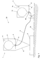
- Fig. 1 shows an apparatus 20 comprising a buoyancy device 1 and a supply unit 11.
- the apparatus 20 may be used to move an object, such as an object 8, from one subsea location to another (or even to or from the surface.) This can be useful for constructing oil well assemblies, laying pipelines, recovering submerged objects, or any other reason for moving objects underwater.
- the buoyancy device 1 is attached, via cables or shackles 6, to the object 8 on sea bed 18, and via a hollow umbilical line 3, to the supply unit 11. Buoyant fluid can be transported between the buoyancy device 1 and supply unit 11 via the umbilical 3, as described further below.
- the buoyancy device 1 comprises a rigid housing 4. Inside the housing 4 is a bag or bladder 5 manufactured from a strong impermeable material such as rubber, polypropylene or reinforced fabric or material. In use, the bag 5 contains a certain amount of buoyant fluid, described further below. A space 7 is defined between the bag 5 and the inside of the housing 4. The inside of the bag 5 is in fluid communication with the umbilical 3, via a proportional valve 9.
- the housing 4 may not be a rigid structure but may be a bag or bladder manufactured from a strong impermeable material such as rubber, polypropylene or reinforced fabric or material.
- a further valve 2 is provided on the outside of the housing 4 to allow water from outside the housing 1 to enter and exit the space 7 between the bag 5 and the inside of the housing 4.
- the supply unit 11 takes on a similar configuration: a bag 15 is provided within a rigid housing 14 and the inside of the bag 15 is in fluid communication with the umbilical 3 via a proportional valve 19. A space 17 is defined between the bag 15 and the inside of the housing 4.
- the supply unit 11 comprises a further valve 12 on the housing 14 to allow water to enter and exit the space 17 between the bag 15 and the inside of the housing 14.
- the supply unit 11 also has weights 16 which cause it to sink and rest on the seabed 18. Buoyant fluid is stored in the bag 15, but regardless of the amount of buoyant fluid, the supply unit 11 will remain on the seabed 18 during use.
- a pump (not shown) is attachable to the valves 2, 12 in order to pump sea water from the surroundings into the spaces 7, 17 between the bags 5, 15 and the housings 4, 14 respectively.
- the buoyant fluid comprising oil, a viscosifying agent and microspheres.
- the oil is preferably a low toxicity oil such as a vegetable oil.
- the viscosifying agent may be organophilic clay for example. The addition of the viscosifying agent gives the buoyant fluid viscoelastic rheological properties. Since the fluid is viscoelastic it can be pumped easily but when the fluid is at rest the increased viscosity keeps the microspheres in place ensuring a consistent material.
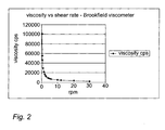
- Viscosity of a sample was measured, as defined in ISO 2555, using a Haake ViscoTester 7L at 23C using an L3 spindle. Viscosity measurements are in centipoise. The results are shown in table 1 below and in Fig. 2. Table 1. rpm viscosity cps 0.3 100560 0.5 55330 0.6 46045 1 29530 1.5 21360 2 16610 2.5 13830 3 11800 4 9350 5 7820 6 6690 10 4580 12 4030 20 2825 30 2220
- the table and graph show that the mixture has viscoelastic properties, that is, at low shear rates the mixture is very viscous. As the shear rate increases, the viscosity decreases. This is an important benefit of certain embodiments of the invention because the high viscosity at low shear rates allows microspheres to be generally evenly distributed within the body of the liquid, rather than rise to the top where they could cause an imbalance in the liquid. The lower viscosity at higher shear rates facilitates the pumping of the fluid into the buoyancy device 1 and supply unit 11 during set up.
- the microspheres are small glass spheres with a hollow centre containing air or another gas. Since they contain air, they are relatively very buoyant compared to any type of liquid. Since the air is trapped inside the glass microspheres, the microspheres and the buoyant fluid as a whole are incompressible.
- the wall thickness of the microspheres may be varied but must be sufficient to withstand the hydrostatic pressure experienced in the depth of water or other liquid in which the apparatus 20 will operate.
- the microspheres significantly contribute to the buoyancy of the buoyant fluid within the bags 5, 15.
- the microspheres are held within the buoyant fluid as a direct consequence of the fluid's viscosity.
- the individual microspheres will not have sufficient buoyancy to move to the top of the (viscous) buoyant fluid but rather, they will remain in the body of the fluid. This allows the microspheres to mix with the buoyant fluid properly, rather than gather at the surface of the buoyant fluid. This in turn provides a more even balance to the buoyancy of the buoyancy device 1.
- Suitable microspheres may be obtained from 3M corporation based in St. Paul Minnesota USA.
- the microspheres can act to viscosify the fluid and so the addition of a further viscosifying agents is not necessary.
- a buoyant fluid was prepared in the following manner: 60g of vegetable oil were placed in a beaker to which was added 40g of S38 glass microspheres from 3M corporation and the mixture was stirred gently to form a fluid viscous mixture with the appearance and consistency of thick cream. To this mixture was added between 0.5 to 1.0 millilitre of water whereupon, surprisingly, the fluid viscosified to form a fluid which at low shear rates exhibits very high viscosity whereas at higher shear rates the viscosity is reduced and the mixture will flow such fluids are described as being viscoelastic. At this point the density of the material was measured and determined to be 0.588 g/cm 3 .
- the table shows that the mixture has viscoelastic properties, that is, at low shear rates the mixture is very viscous while as the shear rate increases, the viscosity decreases.
- microspheres Although inclusion of the microspheres is preferred, certain embodiments of the invention do not require microspheres. Instead a buoyant fluid with a density less than water may be used. The relatively reduced density will provide buoyancy. Many buoyant fluids may be used, including for example diesel or methanol.
- the buoyancy device 1 and supply unit 11 are lowered to the vicinity of the object 8 to be moved.
- the buoyancy device 1 is attached to the object 8 via the cables 6.
- a remotely operated vehicle (ROV) may be utilised to attach the cables 6.
- ROV remotely operated vehicle
- the buoyancy device 1 will be assumed to have sufficient buoyancy at this stage to support itself, but if not its buoyancy can be increased in the same way as that described below for raising the object 8.
- the pump (not shown) is attached to the valve 12 of the supply unit 11 and is activated causing water to be gradually injected into the housing 14 of the supply unit 11 in the space 17 between the bag 15 and the outside of the housing 14 causing an increased pressure within the supply unit 11.
- Valve 19 in the supply unit 11 and valve 9 in the buoyancy device 1 are opened to allow the buoyant fluid, which is being forced out of the bag 15 in the supply unit 14 by the increased pressure, to travel through the umbilical 3 to the bag 5 in the buoyancy device 1.
- the valve 2 in the buoyancy device 1 is also opened. Water in the buoyancy device 1 in the space 7 between the bag 5 and the inside of the housing 4 can escape through the opened valve 2.
- buoyancy of the buoyancy device 1 is thus gradually increased by the gradual addition of buoyant fluid until it is of a sufficient magnitude to lift the object 8.
- the amount of lift or buoyancy imparted is directly proportional to the volume of buoyant fluid pumped into the buoyancy device 1.
- valve 12 Once the object 8 is raised from the seabed 18, the pump attached to the valve 12 can be stopped and the valves 9, 19 are closed to prevent further variation of buoyancy of the buoyancy device 1. Valve 2 is also closed.
- the decrease in depth of the buoyancy device 1 does not result in an increased volume of air and therefore a further increased buoyancy (which would cause upward acceleration of the device and attached object to the surface.)
- the change in buoyancy of the buoyancy device is gradual, rather than sudden as is the situation with a further known technique of removing weights from a buoyancy device.
- embodiments of the invention are more controllable and provide a safer means of raising immersed objects.
- the ROV can then move the buoyancy device 1 and object to the appropriate place, relying on the buoyancy device 1 to provide the lift.
- a pump is attached to the valve 2 and pumps water into the space 7 between the bag 5 and the inside of the housing 4.
- the valves 9, 19, as well as the valve 12 on the supply unit 11, are opened.
- the buoyant fluid is thus forced by the increased pressure in the buoyancy device through the umbilical 3.
- the buoyant fluid proceeds to the bag 15 within the supply unit 11. Water in the supply unit 11 in the space 17 between the bag 15 and the inside of the housing 14 can escape through the opened valve 12.
- the object could be removed from or placed onto another subsea object rather than the seabed.
- the buoyant fluid can provide sufficient buoyancy in a controlled manner to render a subsea element buoyant allowing it to be lifted by a remote operating vehicle or submarine and manoeuvred into the desired position or recovered to the surface from a great depth. Once in place the buoyant fluid can be removed allowing the subsea element to be secured on the sea bed. This technique can also be employed to lift items from the sea bed to the surface in a controlled manner.
- structures can be fabricated on shore filled with buoyant fluid, towed out and placed on the sea bed by pumping out the buoyant fluid such that the structure can be lowered into place.
- buoyancy elements can be constructed of lightweight simple containers which can then filled with the buoyant fluid.
Landscapes
- Engineering & Computer Science (AREA)
- Mechanical Engineering (AREA)
- Ocean & Marine Engineering (AREA)
- Other Liquid Machine Or Engine Such As Wave Power Use (AREA)
- Paper (AREA)
Applications Claiming Priority (1)
| Application Number | Priority Date | Filing Date | Title |
|---|---|---|---|
| GB0611868A GB2427173B8 (en) | 2005-06-15 | 2006-06-15 | Method for use in controlling the buoyancy of a structure |
Publications (2)
| Publication Number | Publication Date |
|---|---|
| EP1867564A1 true EP1867564A1 (fr) | 2007-12-19 |
| EP1867564B1 EP1867564B1 (fr) | 2011-07-27 |
Family
ID=38508797
Family Applications (1)
| Application Number | Title | Priority Date | Filing Date |
|---|---|---|---|
| EP06255294A Active EP1867564B1 (fr) | 2006-06-15 | 2006-10-14 | Méthode et dispositif pour produire flottabilité |
Country Status (4)
| Country | Link |
|---|---|
| US (1) | US7500439B2 (fr) |
| EP (1) | EP1867564B1 (fr) |
| AT (1) | ATE517810T1 (fr) |
| DK (1) | DK1867564T3 (fr) |
Cited By (6)
| Publication number | Priority date | Publication date | Assignee | Title |
|---|---|---|---|---|
| WO2010052493A1 (fr) * | 2008-11-06 | 2010-05-14 | Deep Sea Recovery Ltd | Perfectionnements apportés ou se rapportant à des dispositifs de flottaison |
| US20120063850A1 (en) * | 2010-09-13 | 2012-03-15 | Patrick Collins | Marine-equipment installation method and apparatus |
| DE102012011327A1 (de) * | 2012-06-06 | 2013-12-12 | Fraunhofer-Gesellschaft zur Förderung der angewandten Forschung e.V. | Verfahren und Vorrichtung zum Heben eines Objekts vom Meeresboden |
| GB2517511A (en) * | 2013-08-23 | 2015-02-25 | Aubin Ltd | Method of providing buoyancy |
| EP2985406A3 (fr) * | 2014-08-15 | 2016-03-23 | Aubin Limited | Composition de fluide flottant |
| WO2018051064A1 (fr) * | 2016-09-14 | 2018-03-22 | Aubin Limited | Appareil et procédé permettant de lever et de déplacer un objet sous l'eau |
Families Citing this family (6)
| Publication number | Priority date | Publication date | Assignee | Title |
|---|---|---|---|---|
| GB201401894D0 (en) * | 2014-02-04 | 2014-03-19 | Aubin Ltd | Method of producing a buoyant material |
| US9797525B2 (en) | 2014-05-29 | 2017-10-24 | Ecosse Subsea Systems, Ltd. | Method of governing the elevation, attitude and structural integrity of a pressure-containing vessel in a body of liquid |
| CA2959595C (fr) * | 2014-09-24 | 2018-07-03 | Halliburton Energy Services, Inc. | Agent de reticulation metallique polymere destine a etre utilise dans un fluide de fracturation tolerant au cisaillement |
| KR101969157B1 (ko) * | 2017-09-02 | 2019-08-13 | 장혁수 | 부력발생장치 |
| WO2018093186A1 (fr) * | 2016-11-17 | 2018-05-24 | 장혁수 | Dispositif de production de flottabilité |
| ES2975177T3 (es) | 2017-04-14 | 2024-07-03 | Safe Marine Transfer Llc | Procedimiento y aparato para instalar, ajustar y recuperar elementos de flotación de instalaciones submarinas |
Citations (7)
| Publication number | Priority date | Publication date | Assignee | Title |
|---|---|---|---|---|
| GB1172032A (en) * | 1967-02-23 | 1969-11-26 | S I R S S P A Societa Internaz | Device for Lifting and taking to the Surface Loads Lying on the Bottom of Bodies of Water |
| US4737407A (en) * | 1986-03-10 | 1988-04-12 | Essex Composite Systems | Thermoset plastic pellets and method and apparatus for making such pellets |
| JPS63267528A (ja) * | 1987-04-25 | 1988-11-04 | Mazda Motor Corp | 強化反応射出成形方法 |
| US5516235A (en) | 1991-01-25 | 1996-05-14 | Controlled Lifting International Limited | Method and apparatus of raising objects from the sea bed |
| WO1997031975A1 (fr) * | 1996-03-01 | 1997-09-04 | Raychem Limited | Composition polymere basse densite |
| WO2002072416A1 (fr) * | 2001-03-09 | 2002-09-19 | Controlled Variable Buoyancy Systems Limited | Dispositif flottant |
| US20040033905A1 (en) * | 2002-08-14 | 2004-02-19 | 3M Innovative Properties Company | Drilling fluid containing microspheres and use thereof |
Family Cites Families (12)
| Publication number | Priority date | Publication date | Assignee | Title |
|---|---|---|---|---|
| US3602177A (en) * | 1969-04-01 | 1971-08-31 | Cyclo Mfg Co | Apparatus for raising submerged vessels |
| US3827383A (en) | 1971-07-16 | 1974-08-06 | Us Navy | Salvage method utilizing water emulsified polyester resin and hollow microspheres |
| US3814043A (en) * | 1972-07-25 | 1974-06-04 | L Krout | Ship salvage apparatus |
| US4193057A (en) | 1978-03-20 | 1980-03-11 | Bunker Ramo Corporation | Automatic deployment of horizontal linear sensor array |
| GB2155865A (en) | 1984-03-02 | 1985-10-02 | Balmoral Glassfibre | Buoyancy material |
| US4979451A (en) * | 1989-08-23 | 1990-12-25 | LeRoy Searle | Under water air lift utility bag |
| WO1994004865A1 (fr) | 1992-08-12 | 1994-03-03 | Terrence Jeffrey Corbishley | Ameliorations apportees a un dispositif marin et sous-marin |
| US6409431B1 (en) * | 2000-02-17 | 2002-06-25 | Thomas S. Lynch | Submersible floating dock |
| AU2001244627A1 (en) | 2000-03-29 | 2001-10-08 | Idemitsu Kosan Co. Ltd. | Catalyst for reforming hydrocarbon and method for producing the same |
| GB0115918D0 (en) | 2001-06-29 | 2001-08-22 | Smit Land & Marine Engineering | Flowline delivery |
| FR2852917B1 (fr) | 2003-03-26 | 2005-06-24 | Saipem Sa | Receptacle a compartiments etanches et procede de mise en place pour recuperer des effluents polluants d'une epave |
| GB0512154D0 (en) | 2005-06-15 | 2005-07-20 | Ythan Environmental Services L | Method and apparatus |
-
2006
- 2006-10-10 US US11/545,795 patent/US7500439B2/en active Active
- 2006-10-14 AT AT06255294T patent/ATE517810T1/de not_active IP Right Cessation
- 2006-10-14 DK DK06255294.8T patent/DK1867564T3/da active
- 2006-10-14 EP EP06255294A patent/EP1867564B1/fr active Active
Patent Citations (7)
| Publication number | Priority date | Publication date | Assignee | Title |
|---|---|---|---|---|
| GB1172032A (en) * | 1967-02-23 | 1969-11-26 | S I R S S P A Societa Internaz | Device for Lifting and taking to the Surface Loads Lying on the Bottom of Bodies of Water |
| US4737407A (en) * | 1986-03-10 | 1988-04-12 | Essex Composite Systems | Thermoset plastic pellets and method and apparatus for making such pellets |
| JPS63267528A (ja) * | 1987-04-25 | 1988-11-04 | Mazda Motor Corp | 強化反応射出成形方法 |
| US5516235A (en) | 1991-01-25 | 1996-05-14 | Controlled Lifting International Limited | Method and apparatus of raising objects from the sea bed |
| WO1997031975A1 (fr) * | 1996-03-01 | 1997-09-04 | Raychem Limited | Composition polymere basse densite |
| WO2002072416A1 (fr) * | 2001-03-09 | 2002-09-19 | Controlled Variable Buoyancy Systems Limited | Dispositif flottant |
| US20040033905A1 (en) * | 2002-08-14 | 2004-02-19 | 3M Innovative Properties Company | Drilling fluid containing microspheres and use thereof |
Cited By (12)
| Publication number | Priority date | Publication date | Assignee | Title |
|---|---|---|---|---|
| WO2010052493A1 (fr) * | 2008-11-06 | 2010-05-14 | Deep Sea Recovery Ltd | Perfectionnements apportés ou se rapportant à des dispositifs de flottaison |
| CN102271994B (zh) * | 2008-11-06 | 2014-07-30 | 深海丽卡瑞有限公司 | 有关漂浮装置的改进 |
| US20120063850A1 (en) * | 2010-09-13 | 2012-03-15 | Patrick Collins | Marine-equipment installation method and apparatus |
| EP2428616A3 (fr) * | 2010-09-13 | 2012-12-12 | Aubin Limited | Procédé et appareil pour l'installation d'équipement marin, en particulier des éoliennes offshore |
| US8784011B2 (en) | 2010-09-13 | 2014-07-22 | Aubin Limited | Marine-equipment installation method and apparatus |
| DE102012011327A1 (de) * | 2012-06-06 | 2013-12-12 | Fraunhofer-Gesellschaft zur Förderung der angewandten Forschung e.V. | Verfahren und Vorrichtung zum Heben eines Objekts vom Meeresboden |
| GB2517511A (en) * | 2013-08-23 | 2015-02-25 | Aubin Ltd | Method of providing buoyancy |
| US20150053413A1 (en) * | 2013-08-23 | 2015-02-26 | Aubin Limited | Method of providing buoyancy |
| EP2845792A3 (fr) * | 2013-08-23 | 2015-08-26 | Aubin Limited | Procédé permettant d'assurer la flottabilité |
| EP2985406A3 (fr) * | 2014-08-15 | 2016-03-23 | Aubin Limited | Composition de fluide flottant |
| WO2018051064A1 (fr) * | 2016-09-14 | 2018-03-22 | Aubin Limited | Appareil et procédé permettant de lever et de déplacer un objet sous l'eau |
| US11214340B2 (en) | 2016-09-14 | 2022-01-04 | Aubin Limited | Apparatus and method for lifting and moving an object underwater |
Also Published As
| Publication number | Publication date |
|---|---|
| EP1867564B1 (fr) | 2011-07-27 |
| US20070289519A1 (en) | 2007-12-20 |
| DK1867564T3 (da) | 2011-11-14 |
| US7500439B2 (en) | 2009-03-10 |
| ATE517810T1 (de) | 2011-08-15 |
Similar Documents
| Publication | Publication Date | Title |
|---|---|---|
| EP1867564B1 (fr) | Méthode et dispositif pour produire flottabilité | |
| US5516235A (en) | Method and apparatus of raising objects from the sea bed | |
| US4575282A (en) | System for driving open end pipe piles on the ocean floor using pneumatic evacuation and existing hydrostatic pressure | |
| EP2428616B1 (fr) | Procédé et appareil pour l'installation d'équipement marin, en particulier des éoliennes offshore | |
| US9878761B2 (en) | Large subsea package deployment methods and devices | |
| MX2013004327A (es) | Torre maritima para perforacion y/o produccion. | |
| KR20130041206A (ko) | 수중 유정을 봉쇄하는 방법 및 상기 방법을 실행하는 장치 | |
| GB2463697A (en) | Method of locating a subsea structure for deployment | |
| GB2427173A (en) | Buoyant fluid for use in controlling the buoyancy of a structure | |
| Brown et al. | Performance of hydrostatic anchors in granular soils | |
| EP2845792B1 (fr) | Procédé permettant d'assurer la flottabilité | |
| BRPI0905603A2 (pt) | método de manipular a flutuabilidade de um dispositivo | |
| EP3512769B1 (fr) | Appareil et procédé permettant de lever et de déplacer un objet sous l'eau | |
| WO2015021497A1 (fr) | Procédé et système de support de structures submergées | |
| GB2618994A (en) | Apparatus for raising or lowering a load in a body of water | |
| US20050252685A1 (en) | Floatable drill cuttings bag and method and system for use in cuttings disposal | |
| CN116118958B (zh) | 一种深远海大型养殖装备坐底防吸附装置及其使用方法 | |
| AU682301B2 (en) | A method of raising objects from the sea bed | |
| US3798915A (en) | Offshore apparatus and installation technique | |
| Boeck et al. | Automated landing and mooring in deep-sea environment using suction buckets for unmanned vehicles | |
| Stangroom | Subsea Manipulation of Heavy Loads Using Fresh Water: A Concept Study | |
| EP3631095A1 (fr) | Procédé et système pour former des structures dans un fluide, en particulier sous l'eau |
Legal Events
| Date | Code | Title | Description |
|---|---|---|---|
| PUAI | Public reference made under article 153(3) epc to a published international application that has entered the european phase |
Free format text: ORIGINAL CODE: 0009012 |
|
| AK | Designated contracting states |
Kind code of ref document: A1 Designated state(s): AT BE BG CH CY CZ DE DK EE ES FI FR GB GR HU IE IS IT LI LT LU LV MC NL PL PT RO SE SI SK TR |
|
| AX | Request for extension of the european patent |
Extension state: AL BA HR MK YU |
|
| 17P | Request for examination filed |
Effective date: 20080515 |
|
| 17Q | First examination report despatched |
Effective date: 20080616 |
|
| AKX | Designation fees paid |
Designated state(s): AT BE BG CH CY CZ DE DK EE ES FI FR GB GR HU IE IS IT LI LT LU LV MC NL PL PT RO SE SI SK TR |
|
| GRAP | Despatch of communication of intention to grant a patent |
Free format text: ORIGINAL CODE: EPIDOSNIGR1 |
|
| RBV | Designated contracting states (corrected) |
Designated state(s): AT BE BG CH CY CZ DE DK EE ES FI FR GR HU IE IS IT LI LT LU LV MC NL PL PT RO SE SI SK TR |
|
| GRAS | Grant fee paid |
Free format text: ORIGINAL CODE: EPIDOSNIGR3 |
|
| RAP1 | Party data changed (applicant data changed or rights of an application transferred) |
Owner name: AUBIN LIMITED |
|
| GRAA | (expected) grant |
Free format text: ORIGINAL CODE: 0009210 |
|
| AK | Designated contracting states |
Kind code of ref document: B1 Designated state(s): AT BE BG CH CY CZ DE DK EE ES FI FR GR HU IE IS IT LI LT LU LV MC NL PL PT RO SE SI SK TR |
|
| REG | Reference to a national code |
Ref country code: CH Ref legal event code: EP |
|
| REG | Reference to a national code |
Ref country code: CH Ref legal event code: NV Representative=s name: MURGITROYD & COMPANY |
|
| REG | Reference to a national code |
Ref country code: DE Ref legal event code: R096 Ref document number: 602006023284 Country of ref document: DE Effective date: 20110922 |
|
| REG | Reference to a national code |
Ref country code: NL Ref legal event code: T3 |
|
| REG | Reference to a national code |
Ref country code: DK Ref legal event code: T3 |
|
| REG | Reference to a national code |
Ref country code: AT Ref legal event code: MK05 Ref document number: 517810 Country of ref document: AT Kind code of ref document: T Effective date: 20110727 |
|
| PG25 | Lapsed in a contracting state [announced via postgrant information from national office to epo] |
Ref country code: FI Free format text: LAPSE BECAUSE OF FAILURE TO SUBMIT A TRANSLATION OF THE DESCRIPTION OR TO PAY THE FEE WITHIN THE PRESCRIBED TIME-LIMIT Effective date: 20110727 Ref country code: LT Free format text: LAPSE BECAUSE OF FAILURE TO SUBMIT A TRANSLATION OF THE DESCRIPTION OR TO PAY THE FEE WITHIN THE PRESCRIBED TIME-LIMIT Effective date: 20110727 Ref country code: IS Free format text: LAPSE BECAUSE OF FAILURE TO SUBMIT A TRANSLATION OF THE DESCRIPTION OR TO PAY THE FEE WITHIN THE PRESCRIBED TIME-LIMIT Effective date: 20111127 Ref country code: PT Free format text: LAPSE BECAUSE OF FAILURE TO SUBMIT A TRANSLATION OF THE DESCRIPTION OR TO PAY THE FEE WITHIN THE PRESCRIBED TIME-LIMIT Effective date: 20111128 Ref country code: SE Free format text: LAPSE BECAUSE OF FAILURE TO SUBMIT A TRANSLATION OF THE DESCRIPTION OR TO PAY THE FEE WITHIN THE PRESCRIBED TIME-LIMIT Effective date: 20110727 Ref country code: BE Free format text: LAPSE BECAUSE OF FAILURE TO SUBMIT A TRANSLATION OF THE DESCRIPTION OR TO PAY THE FEE WITHIN THE PRESCRIBED TIME-LIMIT Effective date: 20110727 |
|
| PG25 | Lapsed in a contracting state [announced via postgrant information from national office to epo] |
Ref country code: LV Free format text: LAPSE BECAUSE OF FAILURE TO SUBMIT A TRANSLATION OF THE DESCRIPTION OR TO PAY THE FEE WITHIN THE PRESCRIBED TIME-LIMIT Effective date: 20110727 Ref country code: PL Free format text: LAPSE BECAUSE OF FAILURE TO SUBMIT A TRANSLATION OF THE DESCRIPTION OR TO PAY THE FEE WITHIN THE PRESCRIBED TIME-LIMIT Effective date: 20110727 Ref country code: SI Free format text: LAPSE BECAUSE OF FAILURE TO SUBMIT A TRANSLATION OF THE DESCRIPTION OR TO PAY THE FEE WITHIN THE PRESCRIBED TIME-LIMIT Effective date: 20110727 Ref country code: GR Free format text: LAPSE BECAUSE OF FAILURE TO SUBMIT A TRANSLATION OF THE DESCRIPTION OR TO PAY THE FEE WITHIN THE PRESCRIBED TIME-LIMIT Effective date: 20111028 Ref country code: AT Free format text: LAPSE BECAUSE OF FAILURE TO SUBMIT A TRANSLATION OF THE DESCRIPTION OR TO PAY THE FEE WITHIN THE PRESCRIBED TIME-LIMIT Effective date: 20110727 Ref country code: CY Free format text: LAPSE BECAUSE OF FAILURE TO SUBMIT A TRANSLATION OF THE DESCRIPTION OR TO PAY THE FEE WITHIN THE PRESCRIBED TIME-LIMIT Effective date: 20110727 |
|
| PG25 | Lapsed in a contracting state [announced via postgrant information from national office to epo] |
Ref country code: CZ Free format text: LAPSE BECAUSE OF FAILURE TO SUBMIT A TRANSLATION OF THE DESCRIPTION OR TO PAY THE FEE WITHIN THE PRESCRIBED TIME-LIMIT Effective date: 20110727 Ref country code: SK Free format text: LAPSE BECAUSE OF FAILURE TO SUBMIT A TRANSLATION OF THE DESCRIPTION OR TO PAY THE FEE WITHIN THE PRESCRIBED TIME-LIMIT Effective date: 20110727 |
|
| PG25 | Lapsed in a contracting state [announced via postgrant information from national office to epo] |
Ref country code: EE Free format text: LAPSE BECAUSE OF FAILURE TO SUBMIT A TRANSLATION OF THE DESCRIPTION OR TO PAY THE FEE WITHIN THE PRESCRIBED TIME-LIMIT Effective date: 20110727 Ref country code: IT Free format text: LAPSE BECAUSE OF FAILURE TO SUBMIT A TRANSLATION OF THE DESCRIPTION OR TO PAY THE FEE WITHIN THE PRESCRIBED TIME-LIMIT Effective date: 20110727 Ref country code: RO Free format text: LAPSE BECAUSE OF FAILURE TO SUBMIT A TRANSLATION OF THE DESCRIPTION OR TO PAY THE FEE WITHIN THE PRESCRIBED TIME-LIMIT Effective date: 20110727 |
|
| PLBE | No opposition filed within time limit |
Free format text: ORIGINAL CODE: 0009261 |
|
| STAA | Information on the status of an ep patent application or granted ep patent |
Free format text: STATUS: NO OPPOSITION FILED WITHIN TIME LIMIT |
|
| 26N | No opposition filed |
Effective date: 20120502 |
|
| REG | Reference to a national code |
Ref country code: DE Ref legal event code: R097 Ref document number: 602006023284 Country of ref document: DE Effective date: 20120502 |
|
| PGFP | Annual fee paid to national office [announced via postgrant information from national office to epo] |
Ref country code: IE Payment date: 20121019 Year of fee payment: 7 |
|
| PG25 | Lapsed in a contracting state [announced via postgrant information from national office to epo] |
Ref country code: ES Free format text: LAPSE BECAUSE OF FAILURE TO SUBMIT A TRANSLATION OF THE DESCRIPTION OR TO PAY THE FEE WITHIN THE PRESCRIBED TIME-LIMIT Effective date: 20111107 |
|
| PG25 | Lapsed in a contracting state [announced via postgrant information from national office to epo] |
Ref country code: LU Free format text: LAPSE BECAUSE OF NON-PAYMENT OF DUE FEES Effective date: 20111014 |
|
| PG25 | Lapsed in a contracting state [announced via postgrant information from national office to epo] |
Ref country code: BG Free format text: LAPSE BECAUSE OF FAILURE TO SUBMIT A TRANSLATION OF THE DESCRIPTION OR TO PAY THE FEE WITHIN THE PRESCRIBED TIME-LIMIT Effective date: 20111027 |
|
| PG25 | Lapsed in a contracting state [announced via postgrant information from national office to epo] |
Ref country code: TR Free format text: LAPSE BECAUSE OF FAILURE TO SUBMIT A TRANSLATION OF THE DESCRIPTION OR TO PAY THE FEE WITHIN THE PRESCRIBED TIME-LIMIT Effective date: 20110727 |
|
| PG25 | Lapsed in a contracting state [announced via postgrant information from national office to epo] |
Ref country code: HU Free format text: LAPSE BECAUSE OF FAILURE TO SUBMIT A TRANSLATION OF THE DESCRIPTION OR TO PAY THE FEE WITHIN THE PRESCRIBED TIME-LIMIT Effective date: 20110727 |
|
| REG | Reference to a national code |
Ref country code: IE Ref legal event code: MM4A |
|
| PG25 | Lapsed in a contracting state [announced via postgrant information from national office to epo] |
Ref country code: IE Free format text: LAPSE BECAUSE OF NON-PAYMENT OF DUE FEES Effective date: 20131014 |
|
| PGFP | Annual fee paid to national office [announced via postgrant information from national office to epo] |
Ref country code: DK Payment date: 20141001 Year of fee payment: 9 |
|
| PGFP | Annual fee paid to national office [announced via postgrant information from national office to epo] |
Ref country code: MC Payment date: 20141023 Year of fee payment: 9 Ref country code: CH Payment date: 20141007 Year of fee payment: 9 Ref country code: DE Payment date: 20141002 Year of fee payment: 9 |
|
| REG | Reference to a national code |
Ref country code: DE Ref legal event code: R119 Ref document number: 602006023284 Country of ref document: DE |
|
| REG | Reference to a national code |
Ref country code: DK Ref legal event code: EBP Effective date: 20151031 |
|
| REG | Reference to a national code |
Ref country code: CH Ref legal event code: PL |
|
| PG25 | Lapsed in a contracting state [announced via postgrant information from national office to epo] |
Ref country code: MC Free format text: LAPSE BECAUSE OF NON-PAYMENT OF DUE FEES Effective date: 20151102 |
|
| PG25 | Lapsed in a contracting state [announced via postgrant information from national office to epo] |
Ref country code: CH Free format text: LAPSE BECAUSE OF NON-PAYMENT OF DUE FEES Effective date: 20151031 Ref country code: LI Free format text: LAPSE BECAUSE OF NON-PAYMENT OF DUE FEES Effective date: 20151031 Ref country code: DE Free format text: LAPSE BECAUSE OF NON-PAYMENT OF DUE FEES Effective date: 20160503 |
|
| PG25 | Lapsed in a contracting state [announced via postgrant information from national office to epo] |
Ref country code: DK Free format text: LAPSE BECAUSE OF NON-PAYMENT OF DUE FEES Effective date: 20151031 |
|
| REG | Reference to a national code |
Ref country code: FR Ref legal event code: PLFP Year of fee payment: 11 |
|
| REG | Reference to a national code |
Ref country code: FR Ref legal event code: PLFP Year of fee payment: 12 |
|
| REG | Reference to a national code |
Ref country code: FR Ref legal event code: PLFP Year of fee payment: 13 |
|
| P01 | Opt-out of the competence of the unified patent court (upc) registered |
Effective date: 20230518 |
|
| REG | Reference to a national code |
Ref country code: NL Ref legal event code: PD Owner name: ITALMATCH CHEMICALS GB LIMITED; GB Free format text: DETAILS ASSIGNMENT: CHANGE OF OWNER(S), ASSIGNMENT; FORMER OWNER NAME: AUBIN LIMITED Effective date: 20240712 |
|
| PGFP | Annual fee paid to national office [announced via postgrant information from national office to epo] |
Ref country code: NL Payment date: 20251021 Year of fee payment: 20 |
|
| PGFP | Annual fee paid to national office [announced via postgrant information from national office to epo] |
Ref country code: FR Payment date: 20251029 Year of fee payment: 20 |