EP1867788A2 - Kippverankerungsvorrichtung - Google Patents
Kippverankerungsvorrichtung Download PDFInfo
- Publication number
- EP1867788A2 EP1867788A2 EP07301046A EP07301046A EP1867788A2 EP 1867788 A2 EP1867788 A2 EP 1867788A2 EP 07301046 A EP07301046 A EP 07301046A EP 07301046 A EP07301046 A EP 07301046A EP 1867788 A2 EP1867788 A2 EP 1867788A2
- Authority
- EP
- European Patent Office
- Prior art keywords
- wing
- anchor device
- rocking
- threshing
- link
- Prior art date
- Legal status (The legal status is an assumption and is not a legal conclusion. Google has not performed a legal analysis and makes no representation as to the accuracy of the status listed.)
- Withdrawn
Links
- 230000035515 penetration Effects 0.000 claims abstract description 8
- 238000004873 anchoring Methods 0.000 claims description 13
- 230000007423 decrease Effects 0.000 claims description 2
- 238000004519 manufacturing process Methods 0.000 claims description 2
- 230000000149 penetrating effect Effects 0.000 description 17
- 239000002689 soil Substances 0.000 description 5
- 238000005056 compaction Methods 0.000 description 2
- 239000000463 material Substances 0.000 description 2
- 230000005540 biological transmission Effects 0.000 description 1
- 230000006835 compression Effects 0.000 description 1
- 238000007906 compression Methods 0.000 description 1
- 230000007797 corrosion Effects 0.000 description 1
- 238000005260 corrosion Methods 0.000 description 1
- 238000002788 crimping Methods 0.000 description 1
- 230000000881 depressing effect Effects 0.000 description 1
- 239000010419 fine particle Substances 0.000 description 1
- 239000012634 fragment Substances 0.000 description 1
- 239000011440 grout Substances 0.000 description 1
- 238000010438 heat treatment Methods 0.000 description 1
- 238000002513 implantation Methods 0.000 description 1
- 238000002347 injection Methods 0.000 description 1
- 239000007924 injection Substances 0.000 description 1
- 230000037431 insertion Effects 0.000 description 1
- 238000003780 insertion Methods 0.000 description 1
- 239000002245 particle Substances 0.000 description 1
- 239000011435 rock Substances 0.000 description 1
- 230000035939 shock Effects 0.000 description 1
- 230000006641 stabilisation Effects 0.000 description 1
- 238000011105 stabilization Methods 0.000 description 1
- 238000011144 upstream manufacturing Methods 0.000 description 1
Images


Classifications
-
- E—FIXED CONSTRUCTIONS
- E02—HYDRAULIC ENGINEERING; FOUNDATIONS; SOIL SHIFTING
- E02D—FOUNDATIONS; EXCAVATIONS; EMBANKMENTS; UNDERGROUND OR UNDERWATER STRUCTURES
- E02D5/00—Bulkheads, piles, or other structural elements specially adapted to foundation engineering
- E02D5/74—Means for anchoring structural elements or bulkheads
- E02D5/80—Ground anchors
- E02D5/803—Ground anchors with pivotable anchoring members
-
- E—FIXED CONSTRUCTIONS
- E02—HYDRAULIC ENGINEERING; FOUNDATIONS; SOIL SHIFTING
- E02D—FOUNDATIONS; EXCAVATIONS; EMBANKMENTS; UNDERGROUND OR UNDERWATER STRUCTURES
- E02D5/00—Bulkheads, piles, or other structural elements specially adapted to foundation engineering
- E02D5/74—Means for anchoring structural elements or bulkheads
Definitions
- the present invention relates to a tilting anchor device.
- a tilting anchor device comprises a penetrating part to which is pivotally connected a tie such as a cable or a rigid rod. Front view this penetrating piece has a small cross section and a large longitudinal section in the plane substantially perpendicular to the pulling direction of the tie rod in the service position.
- This piece is introduced into the ground, in a direction substantially identical to the direction of traction by means of a driving bar whose end is connected to the penetrating part.
- This penetration bar carrying at its end the penetrating part is introduced into the ground by any suitable means, manual with impact tools such as a mass or mechanical, electric jackhammer, pneumatic or hydraulic for example.
- the driving bar is withdrawn and a dry traction is exerted on the tie rod.
- This traction causes the rotation of the part hence the term "rocker”, and its important longitudinal section then opposes its withdrawal.
- anchoring devices are numerous, whether in civil engineering, for retaining workpieces, for street furniture structures, for fixing masts, or for plant engineering for stabilization of soil, banks or for the fight against avalanches and landslides.
- a problem is related to the depression.
- a driving bar which is inserted into an inner housing of the penetrating part, said housing can be blind or through, which in this case requires a cylindro-conical hole.
- This rod has the disadvantage of being cylindrical and the user has no opportunity to control the orientation of the penetrating part during the insertion into the ground. The accuracy of the positioning remains a little random while orientation depends largely on the quality of the anchorage.
- the penetrating parts have a central body and a wing by analogy with the profile of an aircraft with a central fuselage and a wing distributed on either side of this fuselage.
- the penetrating piece is introduced into the ground and carries with it a link.
- This link particularly its connection with the penetrating part, must be protected from damage during the introduction, including friction against the elements of the soil, including rock fragments.
- connection must allow unhindered pivoting during the pulling commissioning knowing that the penetrating part is driven into the ground and subjected to fine particles of soil that act as so many points of seizure.
- the prior art essentially provides a hole formed transversely in a core of the penetrating part, but the edges of these holes must be chamfered so as not to weaken the link, which can be costly.
- EP 313936 shows an anchor with a body and a wing, a blind hole in the body to receive the driving bar and an adjustable clevis attached to said body.
- the European patent EP 725862 shows a non-polyvalent connection, intended to receive only a rod and further this arrangement illustrates all of the aforementioned drawbacks.
- the European patent EP 786035 discloses a penetrating piece arranged to generate a large tilting torque during the first pulling commissioning.
- a support boss of the link, cable or rod which makes it possible to increase the distance between the point where the traction force is exerted and the point of pivoting, thus to increase the torque of rotation.
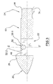
- the anchoring device comprises a body 10 and a blade 12, threshing means 14 and means 16 for receiving a link 18.
- the body 10 comprises a tapered front portion, a medial portion 22, and a rear portion 24.
- the front portion 20 is asymmetrical in that it comprises on the top an elevation 26, with respect to the plane containing the wing and including the median longitudinal axis YY ' , with a recess 28 at the front interface 20 / Middle portion 22. This arrangement is clearly visible in Figure 2.
- the wing 12 comprises two wings 30-1, 30-2, symmetrical, arranged on either side of the body 10.
- each wing 30-1, 30-2 comprises at least one recess, in this case two recesses 32-1D and 32-2D, 32-1G and 32-2 G.
- leading edges of these wings immediately upstream of the recesses, preferably have angles of 45 to 50 ° with respect to the longitudinal axis YY ' .
- Each wing 30-1, 30-2 has a profile of variable thickness.
- a boss 34 starts at the leading edges so as to increase the thickness immediately downstream of the leading edges.
- the thickness is maximum in the middle part 22 of the body 10, to the right of the means 16 for receiving the link 18.
- the thickness decreases on the back to become low and constant in the rear portion 24.
- Each wing optionally comprises flaps 36, which can be advantageously inclined downwards.
- the threshing means 14 comprise a lug 38, male thus projecting at the rear of the device.
- This lug 38 is centered on the axis YY ' preferentially and come from manufacture with the body 10 so as to constitute a monolithic assembly.
- This lug 38 comprises means 40 of anti-rotation, in this case sections 42.
- the means 16 for receiving a link 18 comprise a well 48 passing substantially rectangular shape with an orientation perpendicular to the plane of the wing along the axis ZZ ' .
- a trunnion 50 is disposed in the upper part of the well 48 as is clearly visible in FIGS. 3 and 4. This trunnion is oriented parallel to the plane containing the wing and transversely to the axis YY ' , that is to say say along the XX ' axis.
- This trunnion advantageously has a circular section with two flats 52-1 and 52-2, parallel and oriented along the axis ZZ ' .
- the link 18 is shown in its recessed portion, the termination 54 may be a cable, a strap, a tie rod, a threaded rod, or an anchor rod 56 with butt as shown.
- the opening section corresponds to just the width between flats so as to allow mounting by a perpendicular introduction but which prevents any untimely release as soon as there is a very slight rotation of the anchor rod.
- the stick itself is pivotally mounted about the axis and the dimensions of the stick are such that they prohibit the disengagement out of the well.
- the trunnion has no sharp edges that can weaken in particular the cable terminations.
- the game around the trunnion is interesting in the context of this anchor device that is embedded in the ground. It is understood that precision mechanics must be discarded in favor of mechanically very strong arrangements but that the earth particles are not likely to seize.
- bracket anchor rod When a bracket anchor rod is used, it is noted that the implementation is instantaneous and rocking anchor according to the invention shows all its versatility.
- the fixing is identical by crimping a sleeve or by mounting cable ties.
- the anchoring device is driven by means of manual, pneumatic, hydraulic, electric shock means according to the possibilities.
- the impact means exert their action on the driving bar 46 which is fitted on the lug 38.
- the anti-rotation means 40 of the lug, in this case the lugs 42, and the conjugate profile of the endpiece 44 hollow of this bar depressing 46 allow to control the orientation of the rocking anchor during the phase of penetration into the ground.
- the forces are further exerted over the entire section of the lug and transmitted throughout the body 10 without creating burst pressure as in the case of driving bars penetrating into a hole in the penetrating part.
- the wings of variable thickness cause compression of the penetration column with compaction of the medium, which allows to leave it clean, allowing if necessary an injection of a grout for ensure immobilization in position of the rocking anchor device according to the invention.
- the locking of the anchoring device ie the tilting, is more efficient with a more limited rise in the first pulling commissioning.
- the tapered front portion of the anchor penetrates in a known manner and the two recesses on each of the two wings promote penetration through the obstacles.
- the recesses can also be beveled, which further strengthens the penetrating power.
- the rear fins facilitate in a known manner the pivoting of the device during the first traction of commissioning.
- the tear resistance resistor As soon as the first operating tension is exerted, an angle of inclination of 40 ° with respect to the driving direction is reached, the tear resistance resistor is already 80% of the theoretical maximum value. This maximum value is almost reached from 60 ° and varies little over the remaining 30 °.
- the anchoring device according to the invention is easy to implement, with great precision, which leads to getting closer to each implantation of the theoretical values of resistance to tearing.
Landscapes
- Engineering & Computer Science (AREA)
- Structural Engineering (AREA)
- Life Sciences & Earth Sciences (AREA)
- General Life Sciences & Earth Sciences (AREA)
- Mining & Mineral Resources (AREA)
- Paleontology (AREA)
- Civil Engineering (AREA)
- General Engineering & Computer Science (AREA)
- Piles And Underground Anchors (AREA)
Applications Claiming Priority (1)
| Application Number | Priority Date | Filing Date | Title |
|---|---|---|---|
| FR0651810A FR2901292B1 (fr) | 2006-05-18 | 2006-05-18 | Dispositif d'ancrage a bascule |
Publications (2)
| Publication Number | Publication Date |
|---|---|
| EP1867788A2 true EP1867788A2 (de) | 2007-12-19 |
| EP1867788A3 EP1867788A3 (de) | 2007-12-26 |
Family
ID=37873071
Family Applications (1)
| Application Number | Title | Priority Date | Filing Date |
|---|---|---|---|
| EP07301046A Withdrawn EP1867788A3 (de) | 2006-05-18 | 2007-05-16 | Kippverankerungsvorrichtung |
Country Status (2)
| Country | Link |
|---|---|
| EP (1) | EP1867788A3 (de) |
| FR (1) | FR2901292B1 (de) |
Cited By (1)
| Publication number | Priority date | Publication date | Assignee | Title |
|---|---|---|---|---|
| FR3138155A1 (fr) * | 2023-04-13 | 2024-01-26 | Idelys | Amarre à bascule comportant deux plaques non soudées avec système de blocage |
Family Cites Families (5)
| Publication number | Priority date | Publication date | Assignee | Title |
|---|---|---|---|---|
| FR2564120B1 (fr) * | 1984-05-11 | 1986-11-14 | Inst Francais Du Petrole | Dispositif d'ancrage a element articule ayant une forme coudee |
| DE3533408A1 (de) * | 1985-09-19 | 1987-03-26 | Rockenfeller Kg | Vorrichtung zur verankerung von zuggliedern im erdreich |
| US6237289B1 (en) * | 1996-01-16 | 2001-05-29 | Foresight Products, Inc. | Ground Anchor |
| FR2832439B1 (fr) * | 2001-11-22 | 2004-05-14 | Philippe Cantet | Dispositif d'ancrage au sol a tirant, avec des moyens de protection et avec un profil de penetration a faces concaves |
| GB2402686B (en) * | 2003-04-22 | 2005-08-24 | Platipus Anchors Holdings Ltd | Ground anchor drainage apparatus and a method of installation of ground drainage apparatus |
-
2006
- 2006-05-18 FR FR0651810A patent/FR2901292B1/fr active Active
-
2007
- 2007-05-16 EP EP07301046A patent/EP1867788A3/de not_active Withdrawn
Cited By (1)
| Publication number | Priority date | Publication date | Assignee | Title |
|---|---|---|---|---|
| FR3138155A1 (fr) * | 2023-04-13 | 2024-01-26 | Idelys | Amarre à bascule comportant deux plaques non soudées avec système de blocage |
Also Published As
| Publication number | Publication date |
|---|---|
| FR2901292A1 (fr) | 2007-11-23 |
| FR2901292B1 (fr) | 2008-08-08 |
| EP1867788A3 (de) | 2007-12-26 |
Similar Documents
| Publication | Publication Date | Title |
|---|---|---|
| EP0161190B1 (de) | Verankerungsvorrichtung mit angelinktem geknicktem Teil | |
| CA2714270C (fr) | Ancre de manutention d'elements de construction aux branches divergentes maintenues | |
| EP2909488A1 (de) | Abnehmbare verankerungsvorrichtung zur verwendung als aufhängungsstift | |
| FR2481338A1 (fr) | Dent amovible pour excavateur | |
| FR2633959A1 (fr) | Piece d'ancrage, notamment pour beton | |
| EP2102443A1 (de) | Vorrichtung zur betätigung eines bohrlochwerkzeugs | |
| EP0874941A1 (de) | Automatisches schützentor für hydraulisches werk sowie flussschwelle, dammwasser ablass oder schutz deich | |
| EP0786035B1 (de) | Vorrichtung zum verankern des fundaments eines bauwerks im boden | |
| EP1867788A2 (de) | Kippverankerungsvorrichtung | |
| FR2863633A1 (fr) | Dispositif d'ancrage dans le sol | |
| WO2013114055A1 (fr) | Pieu d'ancrage | |
| FR2992335A1 (fr) | Structure de soutenement, dispositif de soutenement associe et dispositif d'amenagement de bord de piste skiable utilisant ceux-ci | |
| BE1008652A6 (fr) | Pylone pourvu d'un manchon conique interieur. | |
| EP1477613A1 (de) | Bodenanker mit Zuggliedschutz und konkavem Eindringungsprofil | |
| FR2718481A1 (fr) | Pieu fourreau avec blocage. Pour fixation et ancrage au sol. | |
| EP0024221A1 (de) | Schiffsanker, insbesondere für Grossschiffe | |
| FR2954788A1 (fr) | Dispositif d'ancrage dans un sol multicouches | |
| FR3098534A1 (fr) | Ancre de levage pour mur à coffrage intégré et mur à coffrage intégré comportant ladite ancre de levage | |
| CH357085A (fr) | Dispositif d'ancrage pour filet pare-avalanche | |
| FR2488301A1 (fr) | Nouveau procede d'ancrage et dispositifs pour sa mise en oeuvre | |
| WO1979001017A1 (fr) | Nouveau systeme d'ancrage | |
| FR2953231A1 (fr) | Procede de confortement d’un terrain et ouvrage de confortement | |
| FR2645109A1 (fr) | Ancre | |
| CA2202392A1 (fr) | Dispositif d'ancrage de fondation de structure dans le sol | |
| FR2978462A1 (fr) | Barriere de protection contre des blocs devalant un terrain en pente |
Legal Events
| Date | Code | Title | Description |
|---|---|---|---|
| PUAI | Public reference made under article 153(3) epc to a published international application that has entered the european phase |
Free format text: ORIGINAL CODE: 0009012 |
|
| PUAL | Search report despatched |
Free format text: ORIGINAL CODE: 0009013 |
|
| AK | Designated contracting states |
Kind code of ref document: A2 Designated state(s): AT BE BG CH CY CZ DE DK EE ES FI FR GB GR HU IE IS IT LI LT LU LV MC MT NL PL PT RO SE SI SK TR |
|
| AX | Request for extension of the european patent |
Extension state: AL BA HR MK YU |
|
| AK | Designated contracting states |
Kind code of ref document: A3 Designated state(s): AT BE BG CH CY CZ DE DK EE ES FI FR GB GR HU IE IS IT LI LT LU LV MC MT NL PL PT RO SE SI SK TR |
|
| AX | Request for extension of the european patent |
Extension state: AL BA HR MK YU |
|
| RIC1 | Information provided on ipc code assigned before grant |
Ipc: E02D 5/74 20060101ALI20071122BHEP Ipc: E02D 5/80 20060101AFI20071122BHEP |
|
| 17P | Request for examination filed |
Effective date: 20080528 |
|
| 17Q | First examination report despatched |
Effective date: 20080627 |
|
| AKX | Designation fees paid |
Designated state(s): AT BE BG CH CY CZ DE DK EE ES FI FR GB GR HU IE IS IT LI LT LU LV MC MT NL PL PT RO SE SI SK TR |
|
| STAA | Information on the status of an ep patent application or granted ep patent |
Free format text: STATUS: THE APPLICATION IS DEEMED TO BE WITHDRAWN |
|
| 18D | Application deemed to be withdrawn |
Effective date: 20100112 |