EP1867853A2 - Véhicule automobile - Google Patents
Véhicule automobile Download PDFInfo
- Publication number
- EP1867853A2 EP1867853A2 EP07011455A EP07011455A EP1867853A2 EP 1867853 A2 EP1867853 A2 EP 1867853A2 EP 07011455 A EP07011455 A EP 07011455A EP 07011455 A EP07011455 A EP 07011455A EP 1867853 A2 EP1867853 A2 EP 1867853A2
- Authority
- EP
- European Patent Office
- Prior art keywords
- motor vehicle
- vehicle according
- operating
- operating element
- signal
- Prior art date
- Legal status (The legal status is an assumption and is not a legal conclusion. Google has not performed a legal analysis and makes no representation as to the accuracy of the status listed.)
- Withdrawn
Links
Images

Classifications
-
- F—MECHANICAL ENGINEERING; LIGHTING; HEATING; WEAPONS; BLASTING
- F02—COMBUSTION ENGINES; HOT-GAS OR COMBUSTION-PRODUCT ENGINE PLANTS
- F02D—CONTROLLING COMBUSTION ENGINES
- F02D11/00—Arrangements for, or adaptations to, non-automatic engine control initiation means, e.g. operator initiated
- F02D11/06—Arrangements for, or adaptations to, non-automatic engine control initiation means, e.g. operator initiated characterised by non-mechanical control linkages, e.g. fluid control linkages or by control linkages with power drive or assistance
- F02D11/10—Arrangements for, or adaptations to, non-automatic engine control initiation means, e.g. operator initiated characterised by non-mechanical control linkages, e.g. fluid control linkages or by control linkages with power drive or assistance of the electric type
- F02D11/105—Arrangements for, or adaptations to, non-automatic engine control initiation means, e.g. operator initiated characterised by non-mechanical control linkages, e.g. fluid control linkages or by control linkages with power drive or assistance of the electric type characterised by the function converting demand to actuation, e.g. a map indicating relations between an accelerator pedal position and throttle valve opening or target engine torque
-
- B—PERFORMING OPERATIONS; TRANSPORTING
- B60—VEHICLES IN GENERAL
- B60K—ARRANGEMENT OR MOUNTING OF PROPULSION UNITS OR OF TRANSMISSIONS IN VEHICLES; ARRANGEMENT OR MOUNTING OF PLURAL DIVERSE PRIME-MOVERS IN VEHICLES; AUXILIARY DRIVES FOR VEHICLES; INSTRUMENTATION OR DASHBOARDS FOR VEHICLES; ARRANGEMENTS IN CONNECTION WITH COOLING, AIR INTAKE, GAS EXHAUST OR FUEL SUPPLY OF PROPULSION UNITS IN VEHICLES
- B60K31/00—Vehicle fittings, acting on a single sub-unit only, for automatically controlling vehicle speed, i.e. preventing speed from exceeding an arbitrarily established velocity or maintaining speed at a particular velocity, as selected by the vehicle operator
- B60K31/02—Vehicle fittings, acting on a single sub-unit only, for automatically controlling vehicle speed, i.e. preventing speed from exceeding an arbitrarily established velocity or maintaining speed at a particular velocity, as selected by the vehicle operator including electrically actuated servomechanism
- B60K31/04—Vehicle fittings, acting on a single sub-unit only, for automatically controlling vehicle speed, i.e. preventing speed from exceeding an arbitrarily established velocity or maintaining speed at a particular velocity, as selected by the vehicle operator including electrically actuated servomechanism and means for comparing one electrical quantity, e.g. voltage, pulse, waveform, flux, or the like, with another quantity of a like kind, which comparison means is involved in the development of an electrical signal which is fed into the controlling means
- B60K31/042—Vehicle fittings, acting on a single sub-unit only, for automatically controlling vehicle speed, i.e. preventing speed from exceeding an arbitrarily established velocity or maintaining speed at a particular velocity, as selected by the vehicle operator including electrically actuated servomechanism and means for comparing one electrical quantity, e.g. voltage, pulse, waveform, flux, or the like, with another quantity of a like kind, which comparison means is involved in the development of an electrical signal which is fed into the controlling means where at least one electrical quantity is set by the vehicle operator
-
- B—PERFORMING OPERATIONS; TRANSPORTING
- B60—VEHICLES IN GENERAL
- B60W—CONJOINT CONTROL OF VEHICLE SUB-UNITS OF DIFFERENT TYPE OR DIFFERENT FUNCTION; CONTROL SYSTEMS SPECIALLY ADAPTED FOR HYBRID VEHICLES; ROAD VEHICLE DRIVE CONTROL SYSTEMS FOR PURPOSES NOT RELATED TO THE CONTROL OF A PARTICULAR SUB-UNIT
- B60W10/00—Conjoint control of vehicle sub-units of different type or different function
- B60W10/04—Conjoint control of vehicle sub-units of different type or different function including control of propulsion units
- B60W10/06—Conjoint control of vehicle sub-units of different type or different function including control of propulsion units including control of combustion engines
-
- B—PERFORMING OPERATIONS; TRANSPORTING
- B60—VEHICLES IN GENERAL
- B60W—CONJOINT CONTROL OF VEHICLE SUB-UNITS OF DIFFERENT TYPE OR DIFFERENT FUNCTION; CONTROL SYSTEMS SPECIALLY ADAPTED FOR HYBRID VEHICLES; ROAD VEHICLE DRIVE CONTROL SYSTEMS FOR PURPOSES NOT RELATED TO THE CONTROL OF A PARTICULAR SUB-UNIT
- B60W10/00—Conjoint control of vehicle sub-units of different type or different function
- B60W10/18—Conjoint control of vehicle sub-units of different type or different function including control of braking systems
- B60W10/184—Conjoint control of vehicle sub-units of different type or different function including control of braking systems with wheel brakes
-
- B—PERFORMING OPERATIONS; TRANSPORTING
- B60—VEHICLES IN GENERAL
- B60W—CONJOINT CONTROL OF VEHICLE SUB-UNITS OF DIFFERENT TYPE OR DIFFERENT FUNCTION; CONTROL SYSTEMS SPECIALLY ADAPTED FOR HYBRID VEHICLES; ROAD VEHICLE DRIVE CONTROL SYSTEMS FOR PURPOSES NOT RELATED TO THE CONTROL OF A PARTICULAR SUB-UNIT
- B60W30/00—Purposes of road vehicle drive control systems not related to the control of a particular sub-unit, e.g. of systems using conjoint control of vehicle sub-units
- B60W30/14—Adaptive cruise control
- B60W30/16—Control of distance between vehicles, e.g. keeping a distance to preceding vehicle
- B60W30/17—Control of distance between vehicles, e.g. keeping a distance to preceding vehicle with provision for special action when the preceding vehicle comes to a halt, e.g. stop and go
-
- B—PERFORMING OPERATIONS; TRANSPORTING
- B60—VEHICLES IN GENERAL
- B60W—CONJOINT CONTROL OF VEHICLE SUB-UNITS OF DIFFERENT TYPE OR DIFFERENT FUNCTION; CONTROL SYSTEMS SPECIALLY ADAPTED FOR HYBRID VEHICLES; ROAD VEHICLE DRIVE CONTROL SYSTEMS FOR PURPOSES NOT RELATED TO THE CONTROL OF A PARTICULAR SUB-UNIT
- B60W2720/00—Output or target parameters relating to overall vehicle dynamics
- B60W2720/10—Longitudinal speed
- B60W2720/106—Longitudinal acceleration
-
- B—PERFORMING OPERATIONS; TRANSPORTING
- B60—VEHICLES IN GENERAL
- B60W—CONJOINT CONTROL OF VEHICLE SUB-UNITS OF DIFFERENT TYPE OR DIFFERENT FUNCTION; CONTROL SYSTEMS SPECIALLY ADAPTED FOR HYBRID VEHICLES; ROAD VEHICLE DRIVE CONTROL SYSTEMS FOR PURPOSES NOT RELATED TO THE CONTROL OF A PARTICULAR SUB-UNIT
- B60W30/00—Purposes of road vehicle drive control systems not related to the control of a particular sub-unit, e.g. of systems using conjoint control of vehicle sub-units
- B60W30/14—Adaptive cruise control
- B60W30/16—Control of distance between vehicles, e.g. keeping a distance to preceding vehicle
-
- F—MECHANICAL ENGINEERING; LIGHTING; HEATING; WEAPONS; BLASTING
- F02—COMBUSTION ENGINES; HOT-GAS OR COMBUSTION-PRODUCT ENGINE PLANTS
- F02D—CONTROLLING COMBUSTION ENGINES
- F02D41/00—Electrical control of supply of combustible mixture or its constituents
- F02D41/02—Circuit arrangements for generating control signals
- F02D41/04—Introducing corrections for particular operating conditions
- F02D41/10—Introducing corrections for particular operating conditions for acceleration
- F02D41/107—Introducing corrections for particular operating conditions for acceleration and deceleration
Definitions
- the invention relates to a motor vehicle, comprising a motor and a control device for the motor.
- congestion assistance systems have been proposed, which, however, are only known in conjunction with automatic transmissions.
- a distance sensor system is used, which can sense, for example, the distance and / or the movement of the preceding vehicle and drive the engine accordingly, so that a subsequent drive without pressing the accelerator pedal or brake pedal is possible.
- These congestion assistance systems are disadvantageous because they can only be implemented in conjunction with an automatic transmission and require a complex distance sensor.
- the invention is therefore based on the object of specifying a motor vehicle which allows easy operability in stop-and-go journeys, in particular in congestion situations, while avoiding complex sensors.
- a motor vehicle of the type mentioned that at least one manually operable, communicating with the control device control is provided by the actuation at least a digital signal for controlling the vehicle speed can be generated, wherein during actuation of Operating element, the control device in dependence of the signal transmitted by the control element for controlling the motor for accelerating or decelerating the motor vehicle is formed.
- the invention therefore provides, in addition to the usual control elements for braking and accelerating the motor vehicle, in particular the accelerator pedal and the brake pedal, at least one manual, ie by hand, to be operated control element to provide, with the speed of the motor vehicle are controlled can.
- a digital signal for controlling the vehicle speed is generated, wherein in particular the generation of two signals, namely an acceleration signal and a Abbremssignals should be possible.
- the corresponding signal is transmitted to the control device, while the operating element is actuated, that is, as long as, for example, a control lever is pressed accordingly or a switch is held accordingly.
- the signal is designed digitally, that is, it merely indicates whether the operating element is actuated accordingly or not. Therefore, it is also easy to process for the control device.
- the control device is now designed to control the motor for accelerating or decelerating the motor vehicle as a function of the signal transmitted by the operating element. For example, this means that upon receipt of a signal indicative of an acceleration request of the driver, ie an acceleration signal, the engine is driven in a predetermined manner to increase the speed of the motor vehicle, as long as the operating element is actuated, consequently a signal is transmitted.
- a signal indicative of an acceleration request of the driver ie an acceleration signal
- the engine is driven in a predetermined manner to increase the speed of the motor vehicle, as long as the operating element is actuated, consequently a signal is transmitted.
- a signal indicating a braking request of the driver ie a deceleration signal
- the deceleration and / or acceleration behavior is initially defined.
- a characteristic curve can be provided which indicates how much at which speed should be accelerated or decelerated.
- the motor vehicle can be braked to a standstill and be driven accordingly to start driving from standstill by pressing the control.
- the driver of the motor vehicle can also vary the speed of the motor vehicle by way of a permanent actuation of the control element or elements. This can be done easily by hands, a cumbersome operation of the pedals is not required. An additional complex system, such as a traffic jam assistance system, is advantageously not necessary.
- the motor vehicle In a special refinement of the acceleration and / or deceleration behavior, provision can be made for the motor vehicle to be able to be accelerated or decelerated uniformly on the basis of the signal. Accordingly, during the actuation of the operating element, a linear increase or decrease of the speed takes place with time. To actuate the motor, a characteristic curve can be stored which maps this linear behavior to the engine parameters.
- an operating function for changing the previously determined acceleration and / or deceleration behavior can be provided. This makes it possible for a user to influence the acceleration and / or deceleration behavior.
- a further operating element may be provided, for example a controller via which the degree of acceleration can be set.
- Such a further operating element can also be used to select between two discretely selectable acceleration and / or deceleration behaviors, for example between two different characteristic curves or characteristic sets.
- the operating function can be selected by the operating element. Then, for example, be provided that as the operating function a termination of the operation of the control element is provided, wherein after completion of the operation for a predetermined period of time on renewed operation, a changed acceleration and / or deceleration behavior is selectable.
- the driver can select a modified, alternative acceleration and / or deceleration behavior by briefly releasing the actuated operating element. For example, a driver who wants to accelerate faster, let go of the already operated control. If it actuates the operating element again within a predetermined period of time, for example within one second, then the motor vehicle is in turn accelerated, but now with a greater acceleration.
- Such a process may also be iterable, that is, the control element is released at a selected changed acceleration and / or deceleration behavior, it may be selected for the predetermined period of time when pressed again, a second, further modified acceleration and / or deceleration behavior, for example an even faster acceleration level.
- the selection of the changed acceleration and / or deceleration behavior need not be selectable by such a release of the control element, it may also be provided that it is made available for example by a brief actuation of the control element. In this case, for example, to think of a tapping of the control element.
- the functionality of the control element can be further expanded. For example, in a control element to be pressed can be provided that this can be pressed against a resistance in the direction of actuation further, so that in this way a changed acceleration and / or deceleration behavior can be selected.
- the control device is designed to disregard the signals when an actuated gas and / or brake pedal.
- the gas and / or brake pedal On the one hand, because of its analogous design, it provides a much more precise control of the acceleration and / or deceleration behavior of the motor vehicle; on the other hand, it is the usual driver element known to the driver, and should therefore always have priority over actuation of the operating element. For example, a full braking may be necessary, which is not accessible via the control. Then, the driver can operate the brake pedal as usual, the signal is considered as the relevant signal from the controller preferred.
- a deceleration signal and an acceleration signal can be generated by the at least one operating element.
- two embodiments are conceivable.
- a deceleration signal and an acceleration signal can be generated by means of the one control element, depending on the type of actuation.
- only one operating element is provided, which, however, can be actuated in several ways.
- a deceleration signal or an acceleration signal is then generated and transmitted to the control device.
- two operating elements are provided, wherein a deceleration signal can be generated via the first operating element and an acceleration signal can be generated via the second operating element.
- two physically separate controls are provided, one of which is clearly associated with deceleration, another clearly accelerating.
- the two control elements in particular their interconnection, designed so that only one signal can be generated with simultaneous operation of the controls.
- the control device is designed for the preferred treatment of only one of these signals.
- the brake signal can be generated or preferably treated by the control device.
- the one or more controls a different vehicle system, in particular a driver assistance system, be assigned controls. If necessary, these can then be changed in their function. In this case, therefore, no additional operating element is provided, but rather an operating element which is installed in the motor vehicle anyway.
- the functionality of a flasher lever can be multiplied by the signal is generated by actuation of the flashing lever perpendicular to the direction of the flashing lights.
- the one or more controls can be assigned to a longitudinal guide system. In particular, distance control systems or cruise control systems are anyway associated with a speed change by a driver.
- keys or an operating lever which normally serve to increase or decrease a regulating speed, can also be designed to generate the signal in the motor vehicle according to the invention. This can be made possible by additional functionality or, for example, by switching between the operating option for the driver assistance system or the cruise control according to the invention.
- the one or more operating elements can be easily reached by a driver for manual actuation, the one or more operating elements can be arranged in the grip area of the hands located on the steering wheel, that is, on or adjacent to a steering wheel. Then the driver does not have to carry out far gripping movements, but receives a simple and comfortable way to regulate the speed of the motor vehicle, for example, in stop-and-go traffic.
- the operating element may also be a control lever arranged on the steering column.
- Such manual control of the vehicle speed can also be made possible only for driving at low speeds, that is to say in particular in the stated application of stop-and-go traffic.
- a limit speed can be provided, up to which the vehicle by means of actuation of the or an operating element can be accelerated is.
- This limit speed may be 50-70 km / h, preferably 60 km / h.
- the safety of the motor vehicle is thus increased because the driver at high speeds can not rely on the - largely predetermined - acceleration and / or deceleration behavior, which can be selected by the control element.
- Such a motor vehicle can also be a motor vehicle with a manual transmission.
- a transmission in this case comprises a clutch and an actuator associated therewith for automatically opening the clutch when braking to a standstill and automatically closing the clutch when starting from standstill, which actuator can be controlled as a function of the signal.
- actuators have heretofore been mostly proposed in the context of spacing systems to enable the standoff system to decelerate the motor vehicle to stall without stalling the engine.
- an actuator can advantageously also be used in the context of the present invention.
- an operating element for controlling the vehicle speed can also be used in a manual transmission, so that the driver no longer has to operate the clutch himself.
- the actuator when the operator actuates the control member with the intention of decelerating, the actuator is activated and it is checked how high, for example, the speed and speed of the motor vehicle are. Falls due to the operation of the control element, the speed of the motor vehicle, for example, less than 10 km / h, so the clutch begins to open, so that is driven with a sliding clutch. To a stop, the clutch is then fully opened, so that a stalling of the engine is prevented. Similarly, the actuator is activated and corresponding checks are made even with an actuation of the or the controls for the purpose of acceleration by the driver. From standstill thus the clutch is closed.
- the actuation of the clutch itself and the switching is designed as independent as possible of the operation of the control element, so that it is easily possible to switch to higher gears, despite the speed control is made only manually by means of the control element.
- control elements for example, after exceeding a limit speed, but in particular but also or additionally by another control element, be activated and / or deactivated. This can be prevented, for example, that it comes to incorrect operation.
- a deactivation of the or the operating elements can also be achieved by operating an accelerator pedal and / or a brake pedal and / or a clutch pedal in a simple manner.
- the motor vehicle then comprises a display device for displaying the activated or deactivated state of the one or more operating elements.
- a display device for displaying the activated or deactivated state of the one or more operating elements.
- Such a display device can be housed for example on the dashboard, but also at any other, easily visible place.
- an automatic braking device may be provided for holding the motor vehicle brought to a standstill by actuation of the or an operating element. Decreases the speed of the motor vehicle by pressing the control accordingly to zero, so a braking device is activated, which prevents the motor vehicle can be set in motion, for example, by the idle gas or by an inclined driving surface again.
- braking devices are known in principle, they are used for example in automatic spacer systems. If the vehicle - either accelerated by pressing the accelerator pedal or by pressing the control - again accelerates, the automatic braking device automatically releases again.
- Such a braking device can be advantageously connected to an interior monitor or the like. It should be checked whether the driver is still properly in the driver's seat. It will For example, it is determined whether the driver brings the motor vehicle to a standstill by actuating the operating element and then leaves the vehicle. In such cases, the braking device is deactivated and another braking system, for example a handbrake, is activated. Alternatively, of course, a warning signal can be given.
- an interior monitor can be configured differently. Thus, a camera may be provided, the recorded images of which are analyzed by image processing, or a sensor may be provided which determines whether the driver's seat is occupied.
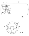
- the 1 shows a motor vehicle 1 according to the invention. It comprises a motor 2, which is controlled by a control device 3 for the motor 2.
- the engine 2 is also assigned a gear 4.
- the transmission 4 may be a manual transmission or an automatic transmission.
- the transmission 4 is controlled by means of a switching unit 5. It is about a manual transmission, the transmission 4 also includes a here only dashed lines indicated clutch 6, which is associated with an actuator 7 for automatically opening the clutch during braking to a standstill and for automatically closing the clutch when starting from a standstill. If the transmission 4 is designed as an automatic transmission, the components 6 and 7 are not required.
- the control device 3 receives signals, according to which it controls the motor 2, from different sources.
- a pedal 9 is provided, which in the case of an automatic transmission includes an accelerator pedal and a brake pedal, in the case of a manual transmission additionally a clutch pedal. Via the pedals 9, an immediate control of the motor 2 or by the clutch pedal of the transmission 4 can take place.
- a driver assistance system 10 is provided for speed control. This also communicates with the control device 3.
- the control device 3 In the area of the steering wheel 8, ie on the steering wheel 8 or adjacent to it, at least one operating element 11 is provided for manual operation, which communicates with the control device 3 and by the operation of at least one digital signal to control the vehicle speed can be generated.
- the control device 3 is designed to control the motor 2 for accelerating or decelerating the motor vehicle 1 as a function of the signal transmitted here by the operating element 11.
- Embodiments for the one or more operating elements 11 are shown in Figures 2 and 3.
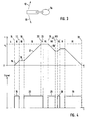
- Fig. 2 shows the steering wheel 8 from the perspective of a driver. It comprises two operating elements 11a, 11b labeled "-" and "+". Upon actuation of the operating element 11a, a deceleration signal is generated and transmitted to the control device 3, which activates the motor 2 in such a way that the motor vehicle during the operating time of the operating element 11a, which is easily accessible by the hands located on the steering wheel 8, evenly decelerates. By actuation of the operating element 11 b, an acceleration signal is generated and transmitted to the control device 3, which provides analog for a uniform acceleration of the motor vehicle 1.
- the two operating elements 11a and 11b or the control device 3 are designed such that only one signal, preferably that of the operating element 11a, is generated or processed during simultaneous actuation of the operating elements 11a and 11b.
- FIG. 3 shows an operating lever 11c arranged on the steering column of the steering wheel 8, which can be used as an alternative to the operating elements 11a and 11b.
- an acceleration signal is generated.
- arrow 13 moves, a Abbremssignal is generated.
- the operating lever 11c also serves to operate the driver assistance system 10 in this exemplary embodiment. This is a speed control system. If the operating lever 11c is used to control the driver assistance system 10, a movement in the direction of the arrow 12 triggers an increase in the regulating speed by 10 km / h, a movement along the arrow 13 a reduction of the regulating speed by 10 km / h. Regardless of the purpose for which the operating lever 11c is currently used, a driver nevertheless associates an acceleration or braking action with movements in different directions.
- the change of functionality can be configured in various ways. On the one hand, it is conceivable that a further operating element is provided with which it can be selected whether the operating lever 11 c is used to operate the driver assistance system 10 or to generate deceleration or acceleration signals. However, it is also conceivable that the operating lever 11c only when activated driver assistance system 10 is used to control the driver assistance system 10, but otherwise for generating Abbrems- or acceleration signals.
- the actual speed v of the motor vehicle 1 is plotted against the time t, in the lower graph the presence of an acceleration signal (solid line ) or a deceleration signal (dotted line).
- These signals can be generated by operating the operating elements 11a, 11b or alternatively by operating the operating lever 11c.
- a first time interval I the motor vehicle is at a standstill.
- the control element 11b is actuated or the operating lever 11 c deflected as actuation in the direction of the arrow 12.
- an acceleration signal 15 is generated for the duration of the actuation, time interval II.
- the acceleration signal 15 has the effect that the speed v of the motor vehicle 1 increases linearly with a predetermined gradient 16.
- the operation of the operating element 11 ends, so that the signal 15 is terminated. Accordingly, the speed v of the motor vehicle 1 is not further increased.
- an acceleration signal 20 is again generated by actuation of the or the operating elements 11.
- the motor vehicle 1 accelerates linearly along a gradient 21, wherein the slope is the same as in the interval 11.
- a limit speed V g is reached, which must not be exceeded by actuation of the or the operating elements 11. Consequently, the control device 3 in the engine 2 does not further control the acceleration of the motor vehicle 1, so that the speed in the time interval V constantly corresponds to the limit speed, although the operating element 11b or the operating lever 11c continues to be operated.
- the operation of the operating member 11b and the lever 11c is terminated.
- the motor vehicle 1 continues to move at the constant speed V g .
- the operating element 11a or the operating lever 11c is now actuated in the direction of the arrow 13.
- a deceleration signal 25 is generated.
- the control device 3 receives the Abbremssignal 25, ie in the time interval VII, the vehicle speed v along a gradient 26, the slope amount of which is the same as that of the gradient 16 and 21, linearly reduced.
- the actuation of the operating element 11a or of the operating lever 11c ends, so that the speed in the following time interval VIII remains unchanged.
- an acceleration signal 28 is generated, so that the motor vehicle 1 is accelerated again.
- no actuation of the operating element or controls 11 follows, so that the speed remains constant.
- the time interval XI is then in turn by actuation of the corresponding control element 11 a or 11 c generates a Abbremssignal 29, wherein the control element is held until the vehicle has come to a standstill at the time 30 again.
- the actuator 7 is activated when the acceleration signal is generated, so that, for example, when starting from a standstill, the clutch is closed accordingly. Similarly, the actuator 7 is activated even when generating a Abbremssignals, so that the clutch is opened when the motor vehicle 1 approaches the standstill. If the motor vehicle has been brought to a standstill by actuation of the corresponding operating element 11a or 11c along the arrow 13, then one will not be closer shown automatic braking device activated, which keeps the motor vehicle 1 at a standstill.
- the actual speed v of the motor vehicle 1 is plotted against the time t, in the lower graph, the signal, here the acceleration signal, against the time t.
- the signal here the acceleration signal
- the speed is increased as usual according to the predetermined acceleration and deceleration behavior linearly along the gradient 32 with a predetermined gradient.
- the acceleration signal 31 ends by ending the actuation of the corresponding control element 11 at the time 33, the vehicle continues to move at constant speed, as is known.
- a renewed generation of an acceleration signal leads to a changed acceleration behavior for a predetermined period of time.
Landscapes
- Engineering & Computer Science (AREA)
- Mechanical Engineering (AREA)
- Chemical & Material Sciences (AREA)
- Combustion & Propulsion (AREA)
- Transportation (AREA)
- Automation & Control Theory (AREA)
- General Engineering & Computer Science (AREA)
- Controls For Constant Speed Travelling (AREA)
- Control Of Electric Motors In General (AREA)
Applications Claiming Priority (1)
| Application Number | Priority Date | Filing Date | Title |
|---|---|---|---|
| DE102006027548.9A DE102006027548B4 (de) | 2006-06-14 | 2006-06-14 | Kraftfahrzeug |
Publications (2)
| Publication Number | Publication Date |
|---|---|
| EP1867853A2 true EP1867853A2 (fr) | 2007-12-19 |
| EP1867853A3 EP1867853A3 (fr) | 2014-05-21 |
Family
ID=38267667
Family Applications (1)
| Application Number | Title | Priority Date | Filing Date |
|---|---|---|---|
| EP07011455.8A Withdrawn EP1867853A3 (fr) | 2006-06-14 | 2007-06-12 | Véhicule automobile |
Country Status (2)
| Country | Link |
|---|---|
| EP (1) | EP1867853A3 (fr) |
| DE (1) | DE102006027548B4 (fr) |
Cited By (1)
| Publication number | Priority date | Publication date | Assignee | Title |
|---|---|---|---|---|
| CN102756731A (zh) * | 2011-04-26 | 2012-10-31 | 奥迪股份公司 | 包括驾驶员辅助系统的机动车 |
Families Citing this family (4)
| Publication number | Priority date | Publication date | Assignee | Title |
|---|---|---|---|---|
| DE102010007899B4 (de) * | 2010-02-13 | 2014-05-28 | Audi Ag | Kraftfahrzeug mit einem Längsführungssystem mit STOP- & GO-Funktion und einer automatisch einlegbaren Parkbremse |
| US9643606B2 (en) | 2015-04-14 | 2017-05-09 | Ford Global Technologies, Llc | Vehicle control in traffic conditions |
| CN106438060B (zh) * | 2016-12-19 | 2022-11-04 | 江苏悦达黄海拖拉机制造有限公司 | 一种数字模拟双信号电子油门及其防误踩方法 |
| DE102020211792A1 (de) | 2020-09-21 | 2022-03-24 | Robert Bosch Gesellschaft mit beschränkter Haftung | Verfahren zum Betrieb einer Fahrzeugbedienvorrichtung und Fahrzeugbedienvorrichtung |
Family Cites Families (6)
| Publication number | Priority date | Publication date | Assignee | Title |
|---|---|---|---|---|
| DE10010747A1 (de) * | 2000-03-04 | 2001-09-20 | Volkswagen Ag | Multifunktions-Bedienelement |
| DE10219800A1 (de) * | 2002-05-03 | 2003-11-13 | Bosch Gmbh Robert | Verfahren und Vorrichtung zur Geschwindigkeitsregelung eines Kraftfahrzeugs und Bedienelement |
| DE10360777A1 (de) * | 2003-12-23 | 2005-07-28 | Robert Bosch Gmbh | Geschwindigkeitsregler für Kraftfahrzeuge, mit automatischer Abschaltfunktion |
| DE102005044968A1 (de) * | 2004-09-28 | 2006-05-11 | Continental Teves Ag & Co. Ohg | Fahrer-Assistenzsystem |
| DE102005036924A1 (de) * | 2005-08-05 | 2007-02-08 | Bayerische Motoren Werke Ag | Fahrerassistenzsystem für ein Kraftfahrzeug |
| DE102005036923A1 (de) * | 2005-08-05 | 2007-02-08 | Bayerische Motoren Werke Ag | Bedieneinrichtung für ein Fahrerassistenzsystem für ein Kraftfahrzeug |
-
2006
- 2006-06-14 DE DE102006027548.9A patent/DE102006027548B4/de not_active Expired - Fee Related
-
2007
- 2007-06-12 EP EP07011455.8A patent/EP1867853A3/fr not_active Withdrawn
Non-Patent Citations (1)
| Title |
|---|
| None |
Cited By (4)
| Publication number | Priority date | Publication date | Assignee | Title |
|---|---|---|---|---|
| CN102756731A (zh) * | 2011-04-26 | 2012-10-31 | 奥迪股份公司 | 包括驾驶员辅助系统的机动车 |
| EP2517936A3 (fr) * | 2011-04-26 | 2013-08-28 | Audi AG | Véhicule automobile comprenant un système d'assistance au conducteur |
| CN102756731B (zh) * | 2011-04-26 | 2015-08-12 | 奥迪股份公司 | 包括驾驶员辅助系统的机动车 |
| US9187067B2 (en) | 2011-04-26 | 2015-11-17 | Audi Ag | Motor vehicle with driver assistance system |
Also Published As
| Publication number | Publication date |
|---|---|
| DE102006027548A1 (de) | 2007-12-20 |
| EP1867853A3 (fr) | 2014-05-21 |
| DE102006027548B4 (de) | 2014-11-13 |
Similar Documents
| Publication | Publication Date | Title |
|---|---|---|
| DE10320722B4 (de) | Geschwindigkeitsregler mit Stop-Funktion | |
| EP2517936B1 (fr) | Véhicule automobile comprenant un système d'assistance au conducteur | |
| EP1922222B1 (fr) | Dispositif de commande d'un systeme d'assistance au conducteur d'un vehicule automobile | |
| EP1343669B2 (fr) | Procede et dispositif pour piloter une installation de freinage d'automobile | |
| EP2162337B1 (fr) | Régulateur de vitesse pour véhicules automobiles | |
| EP1867516B1 (fr) | Véhicule automobile | |
| DE102014015656A1 (de) | Betriebsverfahren für eine Geschwindigkeitsregelanlage | |
| WO2001074618A1 (fr) | Mode de manoeuvre pour vehicules a embrayage automatise | |
| EP2838771B1 (fr) | Procédé permettant de passer d'un mode roue libre ou régime de ralenti d'un véhicule automobile à un mode coupure de l'alimentation | |
| DE102015003344B4 (de) | Betriebsverfahren für eine Geschwindigkeitsregelanlage eines Kraftfahrzeugs und Kraftfahrzeug | |
| WO2021032520A1 (fr) | Procédé de commande de la mise en prise et/ou de la libération d'un mécanisme de verrouillage de stationnement d'une boîte de vitesses d'un véhicule, en particulier d'un véhicule automobile | |
| EP1943122A1 (fr) | Vehicule | |
| DE10152632A1 (de) | Kraftfahrzeug mit einem Geschwindigkeitsregler und einer Abstandssensorik | |
| DE102012205263B4 (de) | Geschwindigkeitsregelsystem mit einem berührungssensitiven Bedienelement | |
| DE102006027548B4 (de) | Kraftfahrzeug | |
| DE102009021662A1 (de) | Verfahren zum Betreiben eines Fahrzeugs mit einem rekuperativen Bremssystem | |
| EP1930614B1 (fr) | Dispositif pour l'actionnement d'un embrayage dans un véhicule | |
| DE102017213978B4 (de) | Verfahren zum assistierten Parken eines Kraftfahrzeugs und Steuervorrichtung für ein Kraftfahrzeug | |
| DE3507330A1 (de) | Hydraulische bremsanlage mit anfahrhilfe | |
| DE102020207313B4 (de) | Fahrerassistenzsystem für ein Kraftfahrzeug und Kraftfahrzeug mit einem Fahrerassistenzsystem | |
| DE102017208993A1 (de) | Abstandseinstellung mittels Fußpedalen | |
| WO2008058945A1 (fr) | Procédé et dispositif d'exploitation d'un système de régulation de vitesse | |
| DE102011105690B4 (de) | Einstellvorrichtung für Assistenzsysteme | |
| DE19841838A1 (de) | Einrichtung sowie Verfahren zur Ansteuerung von beschleunigenden und verzögernden Aggregaten bei Kraftfahrzeugen | |
| DE102008031716A1 (de) | Verfahren zur Sollgeschwindigkeitsvorgabe für ein Geschwindigkeitsregelsystem |
Legal Events
| Date | Code | Title | Description |
|---|---|---|---|
| PUAI | Public reference made under article 153(3) epc to a published international application that has entered the european phase |
Free format text: ORIGINAL CODE: 0009012 |
|
| AK | Designated contracting states |
Kind code of ref document: A2 Designated state(s): AT BE BG CH CY CZ DE DK EE ES FI FR GB GR HU IE IS IT LI LT LU LV MC MT NL PL PT RO SE SI SK TR |
|
| AX | Request for extension of the european patent |
Extension state: AL BA HR MK YU |
|
| PUAL | Search report despatched |
Free format text: ORIGINAL CODE: 0009013 |
|
| AK | Designated contracting states |
Kind code of ref document: A3 Designated state(s): AT BE BG CH CY CZ DE DK EE ES FI FR GB GR HU IE IS IT LI LT LU LV MC MT NL PL PT RO SE SI SK TR |
|
| AX | Request for extension of the european patent |
Extension state: AL BA HR MK RS |
|
| RIC1 | Information provided on ipc code assigned before grant |
Ipc: B60W 10/06 20060101ALI20140415BHEP Ipc: F02D 11/02 20060101AFI20140415BHEP Ipc: F02D 11/10 20060101ALI20140415BHEP Ipc: B60K 31/04 20060101ALI20140415BHEP |
|
| 17P | Request for examination filed |
Effective date: 20140723 |
|
| RBV | Designated contracting states (corrected) |
Designated state(s): AT BE BG CH CY CZ DE DK EE ES FI FR GB GR HU IE IS IT LI LT LU LV MC MT NL PL PT RO SE SI SK TR |
|
| AKX | Designation fees paid |
Designated state(s): DE FR GB IT |
|
| AXX | Extension fees paid |
Extension state: MK Extension state: BA Extension state: HR Extension state: AL Extension state: RS |
|
| STAA | Information on the status of an ep patent application or granted ep patent |
Free format text: STATUS: THE APPLICATION HAS BEEN WITHDRAWN |
|
| 18W | Application withdrawn |
Effective date: 20160802 |