EP1867868B1 - Vanne d'injection de carburant dotée d'une soupape de commande de sécurité - Google Patents
Vanne d'injection de carburant dotée d'une soupape de commande de sécurité Download PDFInfo
- Publication number
- EP1867868B1 EP1867868B1 EP07107002A EP07107002A EP1867868B1 EP 1867868 B1 EP1867868 B1 EP 1867868B1 EP 07107002 A EP07107002 A EP 07107002A EP 07107002 A EP07107002 A EP 07107002A EP 1867868 B1 EP1867868 B1 EP 1867868B1
- Authority
- EP
- European Patent Office
- Prior art keywords
- control
- pressure
- fuel injection
- control valve
- chamber
- Prior art date
- Legal status (The legal status is an assumption and is not a legal conclusion. Google has not performed a legal analysis and makes no representation as to the accuracy of the status listed.)
- Not-in-force
Links
- 239000000446 fuel Substances 0.000 title claims abstract description 53
- 238000002347 injection Methods 0.000 claims abstract description 45
- 239000007924 injection Substances 0.000 claims abstract description 45
- 238000007789 sealing Methods 0.000 claims description 23
- 238000002485 combustion reaction Methods 0.000 claims description 8
- 239000002828 fuel tank Substances 0.000 description 3
- 229910000831 Steel Inorganic materials 0.000 description 2
- 230000006835 compression Effects 0.000 description 2
- 238000007906 compression Methods 0.000 description 2
- 239000010959 steel Substances 0.000 description 2
- 230000010355 oscillation Effects 0.000 description 1
Images
Classifications
-
- F—MECHANICAL ENGINEERING; LIGHTING; HEATING; WEAPONS; BLASTING
- F02—COMBUSTION ENGINES; HOT-GAS OR COMBUSTION-PRODUCT ENGINE PLANTS
- F02M—SUPPLYING COMBUSTION ENGINES IN GENERAL WITH COMBUSTIBLE MIXTURES OR CONSTITUENTS THEREOF
- F02M47/00—Fuel-injection apparatus operated cyclically with fuel-injection valves actuated by fluid pressure
- F02M47/02—Fuel-injection apparatus operated cyclically with fuel-injection valves actuated by fluid pressure of accumulator-injector type, i.e. having fuel pressure of accumulator tending to open, and fuel pressure in other chamber tending to close, injection valves and having means for periodically releasing that closing pressure
- F02M47/027—Electrically actuated valves draining the chamber to release the closing pressure
-
- F—MECHANICAL ENGINEERING; LIGHTING; HEATING; WEAPONS; BLASTING
- F02—COMBUSTION ENGINES; HOT-GAS OR COMBUSTION-PRODUCT ENGINE PLANTS
- F02M—SUPPLYING COMBUSTION ENGINES IN GENERAL WITH COMBUSTIBLE MIXTURES OR CONSTITUENTS THEREOF
- F02M63/00—Other fuel-injection apparatus having pertinent characteristics not provided for in groups F02M39/00 - F02M57/00 or F02M67/00; Details, component parts, or accessories of fuel-injection apparatus, not provided for in, or of interest apart from, the apparatus of groups F02M39/00 - F02M61/00 or F02M67/00; Combination of fuel pump with other devices, e.g. lubricating oil pump
- F02M63/0012—Valves
- F02M63/0031—Valves characterized by the type of valves, e.g. special valve member details, valve seat details, valve housing details
-
- F—MECHANICAL ENGINEERING; LIGHTING; HEATING; WEAPONS; BLASTING
- F02—COMBUSTION ENGINES; HOT-GAS OR COMBUSTION-PRODUCT ENGINE PLANTS
- F02M—SUPPLYING COMBUSTION ENGINES IN GENERAL WITH COMBUSTIBLE MIXTURES OR CONSTITUENTS THEREOF
- F02M63/00—Other fuel-injection apparatus having pertinent characteristics not provided for in groups F02M39/00 - F02M57/00 or F02M67/00; Details, component parts, or accessories of fuel-injection apparatus, not provided for in, or of interest apart from, the apparatus of groups F02M39/00 - F02M61/00 or F02M67/00; Combination of fuel pump with other devices, e.g. lubricating oil pump
- F02M63/0012—Valves
- F02M63/0031—Valves characterized by the type of valves, e.g. special valve member details, valve seat details, valve housing details
- F02M63/004—Sliding valves, e.g. spool valves, i.e. whereby the closing member has a sliding movement along a seat for opening and closing
-
- F—MECHANICAL ENGINEERING; LIGHTING; HEATING; WEAPONS; BLASTING
- F02—COMBUSTION ENGINES; HOT-GAS OR COMBUSTION-PRODUCT ENGINE PLANTS
- F02M—SUPPLYING COMBUSTION ENGINES IN GENERAL WITH COMBUSTIBLE MIXTURES OR CONSTITUENTS THEREOF
- F02M63/00—Other fuel-injection apparatus having pertinent characteristics not provided for in groups F02M39/00 - F02M57/00 or F02M67/00; Details, component parts, or accessories of fuel-injection apparatus, not provided for in, or of interest apart from, the apparatus of groups F02M39/00 - F02M61/00 or F02M67/00; Combination of fuel pump with other devices, e.g. lubricating oil pump
- F02M63/0012—Valves
- F02M63/007—Details not provided for in, or of interest apart from, the apparatus of the groups F02M63/0014 - F02M63/0059
- F02M63/0073—Pressure balanced valves
-
- F—MECHANICAL ENGINEERING; LIGHTING; HEATING; WEAPONS; BLASTING
- F02—COMBUSTION ENGINES; HOT-GAS OR COMBUSTION-PRODUCT ENGINE PLANTS
- F02M—SUPPLYING COMBUSTION ENGINES IN GENERAL WITH COMBUSTIBLE MIXTURES OR CONSTITUENTS THEREOF
- F02M63/00—Other fuel-injection apparatus having pertinent characteristics not provided for in groups F02M39/00 - F02M57/00 or F02M67/00; Details, component parts, or accessories of fuel-injection apparatus, not provided for in, or of interest apart from, the apparatus of groups F02M39/00 - F02M61/00 or F02M67/00; Combination of fuel pump with other devices, e.g. lubricating oil pump
- F02M63/0012—Valves
- F02M63/007—Details not provided for in, or of interest apart from, the apparatus of the groups F02M63/0014 - F02M63/0059
- F02M63/0078—Valve member details, e.g. special shape, hollow or fuel passages in the valve member
- F02M63/008—Hollow valve members, e.g. members internally guided
-
- F—MECHANICAL ENGINEERING; LIGHTING; HEATING; WEAPONS; BLASTING
- F02—COMBUSTION ENGINES; HOT-GAS OR COMBUSTION-PRODUCT ENGINE PLANTS
- F02M—SUPPLYING COMBUSTION ENGINES IN GENERAL WITH COMBUSTIBLE MIXTURES OR CONSTITUENTS THEREOF
- F02M2200/00—Details of fuel-injection apparatus, not otherwise provided for
- F02M2200/18—Fuel-injection apparatus having means for maintaining safety not otherwise provided for
-
- F—MECHANICAL ENGINEERING; LIGHTING; HEATING; WEAPONS; BLASTING
- F02—COMBUSTION ENGINES; HOT-GAS OR COMBUSTION-PRODUCT ENGINE PLANTS
- F02M—SUPPLYING COMBUSTION ENGINES IN GENERAL WITH COMBUSTIBLE MIXTURES OR CONSTITUENTS THEREOF
- F02M2200/00—Details of fuel-injection apparatus, not otherwise provided for
- F02M2200/28—Details of throttles in fuel-injection apparatus
-
- F—MECHANICAL ENGINEERING; LIGHTING; HEATING; WEAPONS; BLASTING
- F02—COMBUSTION ENGINES; HOT-GAS OR COMBUSTION-PRODUCT ENGINE PLANTS
- F02M—SUPPLYING COMBUSTION ENGINES IN GENERAL WITH COMBUSTIBLE MIXTURES OR CONSTITUENTS THEREOF
- F02M2547/00—Special features for fuel-injection valves actuated by fluid pressure
- F02M2547/003—Valve inserts containing control chamber and valve piston
Definitions
- Injectors for high-speed, self-igniting internal combustion engines which introduce the fuel directly into a combustion chamber of an internal combustion engine, have long been known from the prior art. So is from the disclosure DE 196 19 523 A1 an injection valve is known, which has a nozzle needle, the one or more injection openings by their longitudinal movement up and heading. Due to the pressure in a control chamber, a closing force is exerted indirectly via a valve piston on the nozzle needle, so that, if in the control chamber a correspondingly high fuel pressure is present, is held in its closed position. If an injection is to be made, the control chamber is connected to a leakage oil space by a ball valve controlled by an electromagnet lifts off the valve seat. The fuel pressure for the injection is provided here via a high-pressure accumulator, which is filled via a high-pressure fuel pump with fuel under high pressure.
- the fuel injection valve according to the invention with the characterizing feature of claim 1 has the advantage that pressure peaks within the fuel injection valve quickly degraded and thus damage to this can be avoided.
- the control valve is designed such that the movable control valve member is pressed against the force of a closing spring at an overpressure in the control chamber and the pressure is thus relaxed in a leakage oil space. This is done solely by the upcoming pressure in the control room, so that the solenoid otherwise moving solenoid does not need to be controlled. This pressure peaks can be broken down effectively and very quickly. It is also possible that the relief valve is omitted in the high-pressure accumulator and any occurring excessive pressure in the high-pressure accumulator instead is reduced via one or more of the connected fuel injection valves.
- control valve member is in the form of a control sleeve which is slidably mounted on a control valve body.
- a pressure stage is provided within the control sleeve, the for ensures that the control sleeve is lifted from the sealing seat when a certain limit pressure is exceeded, which is determined by the surface of the compression stage and the force of the closing spring, thereby causing a relief of the control chamber.
- the sealing sleeve moves back onto the sealing seat and closes the control chamber against the leakage oil space. Therefore, there is no lowering of the fuel pressure in the control chamber below the prevailing in the high-pressure accumulator level, so that the fuel injection valve is ready for a fuel injection at any time.
- control valve member is designed in the form of a control piston which is slidably mounted in a piston bore of the control valve body.
- the annular groove is formed in this case in the control piston, thereby resulting in a resultant force on the control piston, which is directed away from the sealing seat.
- the function is otherwise identical to that of the control valve sleeve.
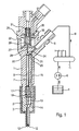
- FIG. 1 a fuel injection valve according to the invention with the fuel-supplying components is shown schematically in longitudinal section.
- the fuel injection valve comprises a holding body 1 and a nozzle body 2, which are pressed against each other by a clamping nut 3.
- a nozzle needle 10 is arranged longitudinally displaceable, which controls the opening of at least one injection opening 12 for their longitudinal movement.
- the fuel is supplied to the injection openings 12 via a pressure chamber 14, which surrounds the valve needle 10 and which can be filled with fuel under high pressure via an inlet channel 15. If the valve needle 10 moves away from the injection openings 12 and thus moves into its open position, fuel will injected from the pressure chamber 14 via the injection openings 12 in a combustion chamber, not shown in the drawing of the internal combustion engine. On the other hand, if the valve needle 10 is in its closed position, that is to say in contact with a valve seat, then the injection openings 12 are closed by the valve needle 10.
- a longitudinal bore 5 is formed, which is coaxial with the valve needle 10 and in which a valve piston 7 is arranged longitudinally displaceable.
- the valve piston 7 abuts on the valve needle 10 via a pressure piece 19, so that it moves in the longitudinal direction synchronously with the valve needle 10.
- At the nozzle body 2 facing the end of the valve piston 7 is surrounded by a spring 17 which is supported on the one hand in a paragraph in the holding body 1 and on the other hand on the pressure piece 19, so that by the force of the spring 17, the pressure piece 19 in the direction of the nozzle and thus the valve needle 10 is pressed into its closed position.
- a high-pressure pump 6 For supplying the fuel under high pressure, a high-pressure pump 6 is provided, which compresses the fuel from a fuel tank 4 and a high-pressure accumulator 11, in which the fuel is kept under high pressure. Via a high pressure line 9 and a high pressure port 8, which is formed on the fuel injection valve, the high pressure fuel is supplied to the fuel injection valve and injected in the manner described via the injection ports 12 into the combustion chamber of the internal combustion engine.
- control piston 7 With its end facing away from the nozzle 2, the control piston 7 defines a control chamber 20, which is connected to the inlet channel 15 via an inlet bore 21, in which an inlet throttle 22 is located.
- the control chamber 20 is also connected via a longitudinal bore 28, which is formed in the holding body 1 and in a control valve body 27, with a leakage oil chamber 32.
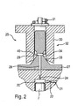
- the longitudinal bore 28 opens into a transverse bore 29, which in turn ends in an annular groove 34 which in FIG. 2 is shown in more detail.
- the control valve 25 comprises a control valve member in the form of a control sleeve 30, which surrounds a piston-shaped portion of the control valve body 27 and is guided on this.
- the control sleeve 30 is in this case longitudinally movable and is in its closed position on a sealing seat 33, so that the annular groove 34 is sealed against the leakage oil chamber 32.
- the control sleeve 30 is acted upon by a closing spring 31, which exerts a closing force on the sealing sleeve 30 and thus presses against the sealing seat 33.
- a closing spring 31 which exerts a closing force on the sealing sleeve 30 and thus presses against the sealing seat 33.
- the sealing sleeve 30 can be lifted from the sealing seat 33, so that the annular groove 34 and thus via the transverse bore 29 and the longitudinal bore 28 and the control chamber 20 are connected to the leakage oil space.
- a pressure stage 40 is formed, which causes by the pressure in the annular groove 34, a resultant hydraulic force acts on the control sleeve 30, which is directed away from the sealing seat 33.
- the surface of the pressure stage 40 which is hydraulically effective in the opening direction and the force of the closing spring 31 are dimensioned so that when a limit pressure in the annular groove 34 is exceeded, the sealing sleeve 30 lifts off from the sealing seat 33 and the fuel present in the annular groove 34 in the Leakage oil room 32 relaxes. As soon as the pressure in the annular groove 34 again falls below the limiting pressure, the sealing sleeve 30 slides back into contact with the sealing seat 33.
- the electromagnet 35 is energized and thereby pulls the sealing sleeve 30 away from the sealing seat 33. Thereby, the annular groove 34 is connected to the leakage oil chamber 32 by always a low fuel pressure prevails.
- control sleeve 30 When overpressure occurs, for example in the inlet channel 15 due to pressure oscillations or due to other pressure surges that may occur, a pressure in the control chamber 20 that is higher than desired can occur. In this case, the control sleeve 30 will reduce the pressure in the manner described above, wherein the limit pressure on the size of the compression stage 40 and the spring force of the closing spring 31 can be adjusted.
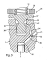
- FIG. 3 an alternative embodiment of the control valve 25 is shown.
- a control piston 37 is provided here, which is guided in a piston bore 36.
- the control piston 37 is also acted upon by a closing spring 31 and is pressed by this against a sealing seat 33.
- a pressure stage 40 ' is provided, which is, however, formed on the inside of the piston bore 36.
- control chamber 20 is identical to the function of the control sleeve 30, as they are in FIG. 2 shown and described above.
- the connection of the control chamber 20 with the inlet bore 21 and the longitudinal bore 24 is slightly different than in the previous embodiment according to FIG. 2 , which is due to the changed geometry of the control valve 25. But here, too, the control chamber 20 is filled or relieved via an inlet bore 21 and a drain channel 24 with an outlet throttle 26 therein.
Landscapes
- Engineering & Computer Science (AREA)
- Chemical & Material Sciences (AREA)
- Combustion & Propulsion (AREA)
- Mechanical Engineering (AREA)
- General Engineering & Computer Science (AREA)
- Physics & Mathematics (AREA)
- Fluid Mechanics (AREA)
- Fuel-Injection Apparatus (AREA)
Claims (9)
- Soupape d'injection de carburant pour moteurs à combustion interne, comprenant une aiguille de soupape (10), qui, par son déplacement longitudinal, commande l'ouverture d'au moins une ouverture d'injection (12), et comprenant un espace de commande (20) dont la pression agit au moins indirectement sur l'aiguille de soupape (10), l'espace de commande (20) pouvant être relié par un canal d'écoulement (28) à un espace de fuite d'huile (32), lequel canal d'écoulement (28) peut être ouvert ou fermé au moyen d'une soupape de commande (25), la soupape de commande (25) comprenant un organe de soupape de commande mobile (30 ; 37) et l'organe de soupape de commande (30 ; 37) étant pressé par une force de fermeture dans la direction d'un siège d'étanchéité (33), le canal d'écoulement (28) dans la soupape de commande (25) débouchant dans un espace annulaire (34) qui est limité par l'organe de soupape de commande (30 37), caractérisée en ce qu'un étage de pression (40; 40') est réalisé dans l'espace annulaire (34) de sorte qu'une force résultante s'exerce du fait de la pression hydraulique dans l'espace annulaire (34) sur l'organe de soupape de commande (30 ; 37) à rencontre de la force de fermeture, de sorte que lors d'un dépassement d'une, pression limite dans l'espace de commande (20), l'organe de soupape de commande (30 ; 37) se soulève du siège d'étanchéité (33) et relie l'espace annulaire (34) à l'espace de fuite d'huile (32).
- Soupape d'injection de carburant selon la revendication 1, caractérisée en ce que l'organe de soupape de commande est réalisé en forme de douille de commande (30) et est monté de manière à pouvoir glisser sur un corps de soupape de commande (27).
- Soupape d'injection de carburant selon la revendication 2, caractérisée en ce que la rainure annulaire (34) est réalisée dans le corps de soupape de commande (27), la rainure annulaire (34) étant limitée vers l'extérieur par la douille de commande (30).
- Soupape d'injection de carburant selon la revendication 3, caractérisée en ce que l'étage de pression (40) est réalisé sur le côté intérieur de la douille de commande (30), de sorte que sous l'effet de la pression dans la rainure annulaire (34), une force résultante s'exerce sur la douille de commande (30) à l'encontre de la force de fermeture.
- Soupape d'injection de carburant selon la revendication 1, caractérisée en ce que l'organe de soupape de commande est réalisé sous forme de piston de commande (37) qui est monté de manière à pouvoir glisser dans un alésage de piston (36) d'un corps de soupape de commande (27).
- Soupape d'injection de carburant selon la revendication 5, caractérisée en ce que la rainure annulaire (34) est réalisée dans le piston de commande (37).
- Soupape d'injection de carburant selon la revendication 6, caractérisée en ce que l'étage de pression (40') est réalisé sur la paroi de l'alésage de piston (36), de sorte que, sous l'effet de la pression hydraulique dans la rainure annulaire (34), une force résultante s'exerce sur le piston de commande (37), laquelle est orientée à l'encontre de la force de fermeture.
- Soupape d'injection de carburant selon l'une quelconque des revendications 1 à 7, caractérisée en ce que la force de fermeture sur l'organe de soupape de commande (30 ; 37) est produite par un ressort de fermeture (31).
- Système d'injection de carburant comprenant une soupape d'injection de carburant selon l'une quelconque des revendications 1 à 8, et un accumulateur haute pression (11), dans lequel du carburant peut être conservé à haute pression, et qui est connecté par le biais d'une conduite haute pression (9) à l'espace de commande (20) d'au moins une soupape d'injection de carburant.
Applications Claiming Priority (1)
| Application Number | Priority Date | Filing Date | Title |
|---|---|---|---|
| DE102006027485A DE102006027485A1 (de) | 2006-06-14 | 2006-06-14 | Kraftstoffeinspritzventil mit Sicherheitssteuerventil |
Publications (2)
| Publication Number | Publication Date |
|---|---|
| EP1867868A1 EP1867868A1 (fr) | 2007-12-19 |
| EP1867868B1 true EP1867868B1 (fr) | 2011-07-20 |
Family
ID=38481640
Family Applications (1)
| Application Number | Title | Priority Date | Filing Date |
|---|---|---|---|
| EP07107002A Not-in-force EP1867868B1 (fr) | 2006-06-14 | 2007-04-26 | Vanne d'injection de carburant dotée d'une soupape de commande de sécurité |
Country Status (3)
| Country | Link |
|---|---|
| EP (1) | EP1867868B1 (fr) |
| AT (1) | ATE517249T1 (fr) |
| DE (1) | DE102006027485A1 (fr) |
Families Citing this family (8)
| Publication number | Priority date | Publication date | Assignee | Title |
|---|---|---|---|---|
| DE102007037824A1 (de) | 2007-08-10 | 2009-02-12 | Robert Bosch Gmbh | Kraftstoffeinspritzventil für Brennkraftmaschinen |
| DE102007037825A1 (de) | 2007-08-10 | 2009-02-12 | Robert Bosch Gmbh | Kraftstoffeinspritzventil für Brennkraftmaschinen |
| DE102007040248A1 (de) | 2007-08-27 | 2009-03-05 | Robert Bosch Gmbh | Steuerventil für einen Kraftstoffinjektor |
| DE102008005534A1 (de) * | 2008-01-22 | 2009-07-23 | Robert Bosch Gmbh | Kraftstoffinjektor |
| DE102008001600A1 (de) * | 2008-05-06 | 2009-11-12 | Robert Bosch Gmbh | Kraftstoff-Injektor mit einem eine Druckstufe aufweisenden Steuerventil |
| DE102009029355A1 (de) * | 2009-09-10 | 2011-03-24 | Robert Bosch Gmbh | Injektor |
| DE102011090060A1 (de) * | 2011-12-28 | 2013-07-04 | Robert Bosch Gmbh | Kraftstoffeinspritzventil für Brennkraftmaschinen |
| CN116480506B (zh) * | 2023-04-28 | 2025-06-27 | 中船动力研究院有限公司 | 喷射装置及发动机 |
Family Cites Families (6)
| Publication number | Priority date | Publication date | Assignee | Title |
|---|---|---|---|---|
| GB9508623D0 (en) * | 1995-04-28 | 1995-06-14 | Lucas Ind Plc | "Fuel injection nozzle" |
| DE10024662B4 (de) * | 2000-05-18 | 2005-12-15 | Siemens Ag | Verfahren zum Betreiben eines Einspritzventils |
| DE10104618A1 (de) * | 2001-02-02 | 2002-08-08 | Bosch Gmbh Robert | Ventil zum Steuern von Flüssigkeiten |
| DE10163693A1 (de) * | 2001-12-21 | 2003-07-10 | Orange Gmbh | Einspritzinjektor für Brennkraftmaschinen |
| US7278593B2 (en) * | 2002-09-25 | 2007-10-09 | Caterpillar Inc. | Common rail fuel injector |
| EP1612403B1 (fr) * | 2004-06-30 | 2007-01-10 | C.R.F. Società Consortile per Azioni | Soupape servo pour controller l'injecteur d'un moteur à combustion interne |
-
2006
- 2006-06-14 DE DE102006027485A patent/DE102006027485A1/de not_active Withdrawn
-
2007
- 2007-04-26 AT AT07107002T patent/ATE517249T1/de active
- 2007-04-26 EP EP07107002A patent/EP1867868B1/fr not_active Not-in-force
Also Published As
| Publication number | Publication date |
|---|---|
| ATE517249T1 (de) | 2011-08-15 |
| EP1867868A1 (fr) | 2007-12-19 |
| DE102006027485A1 (de) | 2007-12-20 |
Similar Documents
| Publication | Publication Date | Title |
|---|---|---|
| EP2171258B1 (fr) | Soupape de commande pour une soupape d'injection de carburant | |
| EP1478840B1 (fr) | Soupape d'injection de carburant pour moteurs a combustion interne | |
| EP2183476B1 (fr) | Soupape d'injection de carburant avec une étanchéité améliorée au niveau du siège d'étanchéité d'une soupape de commande à pression compensée | |
| EP1867868B1 (fr) | Vanne d'injection de carburant dotée d'une soupape de commande de sécurité | |
| WO2008138800A1 (fr) | Injecteur à actionneur piézoélectrique | |
| DE102004053421A1 (de) | Kraftstoffeinspritzvorrichtung | |
| EP1387937B1 (fr) | Soupape d'injection de carburant pour moteurs a combustion, comprenant une chambre d'amortissement reduisant les oscillations de pression | |
| EP1613855B1 (fr) | Injecteur de carburant comportant une soupape asservie libre de fuites | |
| EP1651862B1 (fr) | Soupape de commande pour un injecteur de carburant comprenant un dispositif multiplicateur de pression | |
| EP1404966B1 (fr) | Soupape de commande d'un injecteur de carburant pour la compression/decompression d'une chambre de commande | |
| WO2005015000A1 (fr) | Soupape de commande a compensation de pression pour un injecteur de carburant comprenant un multiplicateur de pression | |
| WO2008049668A1 (fr) | Injecteur d'injection de carburant dans des chambres de combustion de moteurs à combustion interne | |
| DE102007005382A1 (de) | Leckagefreier Injektor | |
| EP2984328B1 (fr) | Injecteur de carburant pour moteurs a combustion interne | |
| DE10132248A1 (de) | Kraftstoffinjektor mit 2-Wege-Ventilsteuerung | |
| DE10307003B3 (de) | Einspritzventil für die Einspritzung von Kraftstoff in eine Verbrennungskraftmaschine | |
| DE102007001365A1 (de) | Injektor mit Steuer- und Schaltkammer | |
| EP2267295A2 (fr) | Injecteur de carburant | |
| EP2655850B1 (fr) | Injecteur de carburant pour moteurs à combustion interne | |
| EP2165069B1 (fr) | Soupape pilote, en particulier pour injecteur de carburant d'un moteur à combustion interne | |
| EP1606511B1 (fr) | Dispositif d'injection de carburant pour moteur a combustion interne | |
| DE102006050033A1 (de) | Injektor, insbesondere Common-Rail-Injektor | |
| DE102012213535A1 (de) | Kraftstoffinjektor | |
| EP2282045B1 (fr) | Soupape d'injection de combustible | |
| WO2016058969A1 (fr) | Soupape d'injection servant à injecter un fluide dans la chambre de combustion d'un moteur a combustion interne |
Legal Events
| Date | Code | Title | Description |
|---|---|---|---|
| PUAI | Public reference made under article 153(3) epc to a published international application that has entered the european phase |
Free format text: ORIGINAL CODE: 0009012 |
|
| AK | Designated contracting states |
Kind code of ref document: A1 Designated state(s): AT BE BG CH CY CZ DE DK EE ES FI FR GB GR HU IE IS IT LI LT LU LV MC MT NL PL PT RO SE SI SK TR |
|
| AX | Request for extension of the european patent |
Extension state: AL BA HR MK YU |
|
| 17P | Request for examination filed |
Effective date: 20080619 |
|
| AKX | Designation fees paid |
Designated state(s): AT BE BG CH CY CZ DE DK EE ES FI FR GB GR HU IE IS IT LI LT LU LV MC MT NL PL PT RO SE SI SK TR |
|
| GRAP | Despatch of communication of intention to grant a patent |
Free format text: ORIGINAL CODE: EPIDOSNIGR1 |
|
| GRAS | Grant fee paid |
Free format text: ORIGINAL CODE: EPIDOSNIGR3 |
|
| GRAA | (expected) grant |
Free format text: ORIGINAL CODE: 0009210 |
|
| AK | Designated contracting states |
Kind code of ref document: B1 Designated state(s): AT BE BG CH CY CZ DE DK EE ES FI FR GB GR HU IE IS IT LI LT LU LV MC MT NL PL PT RO SE SI SK TR |
|
| REG | Reference to a national code |
Ref country code: GB Ref legal event code: FG4D Free format text: NOT ENGLISH |
|
| REG | Reference to a national code |
Ref country code: CH Ref legal event code: EP |
|
| REG | Reference to a national code |
Ref country code: DE Ref legal event code: R096 Ref document number: 502007007704 Country of ref document: DE Effective date: 20110908 |
|
| REG | Reference to a national code |
Ref country code: NL Ref legal event code: VDEP Effective date: 20110720 |
|
| PG25 | Lapsed in a contracting state [announced via postgrant information from national office to epo] |
Ref country code: NL Free format text: LAPSE BECAUSE OF FAILURE TO SUBMIT A TRANSLATION OF THE DESCRIPTION OR TO PAY THE FEE WITHIN THE PRESCRIBED TIME-LIMIT Effective date: 20110720 Ref country code: IS Free format text: LAPSE BECAUSE OF FAILURE TO SUBMIT A TRANSLATION OF THE DESCRIPTION OR TO PAY THE FEE WITHIN THE PRESCRIBED TIME-LIMIT Effective date: 20111120 Ref country code: FI Free format text: LAPSE BECAUSE OF FAILURE TO SUBMIT A TRANSLATION OF THE DESCRIPTION OR TO PAY THE FEE WITHIN THE PRESCRIBED TIME-LIMIT Effective date: 20110720 Ref country code: SE Free format text: LAPSE BECAUSE OF FAILURE TO SUBMIT A TRANSLATION OF THE DESCRIPTION OR TO PAY THE FEE WITHIN THE PRESCRIBED TIME-LIMIT Effective date: 20110720 Ref country code: PT Free format text: LAPSE BECAUSE OF FAILURE TO SUBMIT A TRANSLATION OF THE DESCRIPTION OR TO PAY THE FEE WITHIN THE PRESCRIBED TIME-LIMIT Effective date: 20111121 Ref country code: LT Free format text: LAPSE BECAUSE OF FAILURE TO SUBMIT A TRANSLATION OF THE DESCRIPTION OR TO PAY THE FEE WITHIN THE PRESCRIBED TIME-LIMIT Effective date: 20110720 |
|
| REG | Reference to a national code |
Ref country code: IE Ref legal event code: FD4D |
|
| PG25 | Lapsed in a contracting state [announced via postgrant information from national office to epo] |
Ref country code: CY Free format text: LAPSE BECAUSE OF FAILURE TO SUBMIT A TRANSLATION OF THE DESCRIPTION OR TO PAY THE FEE WITHIN THE PRESCRIBED TIME-LIMIT Effective date: 20110720 Ref country code: LV Free format text: LAPSE BECAUSE OF FAILURE TO SUBMIT A TRANSLATION OF THE DESCRIPTION OR TO PAY THE FEE WITHIN THE PRESCRIBED TIME-LIMIT Effective date: 20110720 Ref country code: GR Free format text: LAPSE BECAUSE OF FAILURE TO SUBMIT A TRANSLATION OF THE DESCRIPTION OR TO PAY THE FEE WITHIN THE PRESCRIBED TIME-LIMIT Effective date: 20111021 Ref country code: SI Free format text: LAPSE BECAUSE OF FAILURE TO SUBMIT A TRANSLATION OF THE DESCRIPTION OR TO PAY THE FEE WITHIN THE PRESCRIBED TIME-LIMIT Effective date: 20110720 Ref country code: PL Free format text: LAPSE BECAUSE OF FAILURE TO SUBMIT A TRANSLATION OF THE DESCRIPTION OR TO PAY THE FEE WITHIN THE PRESCRIBED TIME-LIMIT Effective date: 20110720 |
|
| PG25 | Lapsed in a contracting state [announced via postgrant information from national office to epo] |
Ref country code: IE Free format text: LAPSE BECAUSE OF FAILURE TO SUBMIT A TRANSLATION OF THE DESCRIPTION OR TO PAY THE FEE WITHIN THE PRESCRIBED TIME-LIMIT Effective date: 20110720 Ref country code: SK Free format text: LAPSE BECAUSE OF FAILURE TO SUBMIT A TRANSLATION OF THE DESCRIPTION OR TO PAY THE FEE WITHIN THE PRESCRIBED TIME-LIMIT Effective date: 20110720 Ref country code: CZ Free format text: LAPSE BECAUSE OF FAILURE TO SUBMIT A TRANSLATION OF THE DESCRIPTION OR TO PAY THE FEE WITHIN THE PRESCRIBED TIME-LIMIT Effective date: 20110720 |
|
| PLBE | No opposition filed within time limit |
Free format text: ORIGINAL CODE: 0009261 |
|
| STAA | Information on the status of an ep patent application or granted ep patent |
Free format text: STATUS: NO OPPOSITION FILED WITHIN TIME LIMIT |
|
| PG25 | Lapsed in a contracting state [announced via postgrant information from national office to epo] |
Ref country code: RO Free format text: LAPSE BECAUSE OF FAILURE TO SUBMIT A TRANSLATION OF THE DESCRIPTION OR TO PAY THE FEE WITHIN THE PRESCRIBED TIME-LIMIT Effective date: 20110720 Ref country code: EE Free format text: LAPSE BECAUSE OF FAILURE TO SUBMIT A TRANSLATION OF THE DESCRIPTION OR TO PAY THE FEE WITHIN THE PRESCRIBED TIME-LIMIT Effective date: 20110720 |
|
| 26N | No opposition filed |
Effective date: 20120423 |
|
| PG25 | Lapsed in a contracting state [announced via postgrant information from national office to epo] |
Ref country code: DK Free format text: LAPSE BECAUSE OF FAILURE TO SUBMIT A TRANSLATION OF THE DESCRIPTION OR TO PAY THE FEE WITHIN THE PRESCRIBED TIME-LIMIT Effective date: 20110720 |
|
| REG | Reference to a national code |
Ref country code: DE Ref legal event code: R097 Ref document number: 502007007704 Country of ref document: DE Effective date: 20120423 |
|
| BERE | Be: lapsed |
Owner name: ROBERT BOSCH G.M.B.H. Effective date: 20120430 |
|
| PG25 | Lapsed in a contracting state [announced via postgrant information from national office to epo] |
Ref country code: MC Free format text: LAPSE BECAUSE OF NON-PAYMENT OF DUE FEES Effective date: 20120430 |
|
| REG | Reference to a national code |
Ref country code: CH Ref legal event code: PL |
|
| PG25 | Lapsed in a contracting state [announced via postgrant information from national office to epo] |
Ref country code: LI Free format text: LAPSE BECAUSE OF NON-PAYMENT OF DUE FEES Effective date: 20120430 Ref country code: BE Free format text: LAPSE BECAUSE OF NON-PAYMENT OF DUE FEES Effective date: 20120430 Ref country code: CH Free format text: LAPSE BECAUSE OF NON-PAYMENT OF DUE FEES Effective date: 20120430 |
|
| PG25 | Lapsed in a contracting state [announced via postgrant information from national office to epo] |
Ref country code: ES Free format text: LAPSE BECAUSE OF FAILURE TO SUBMIT A TRANSLATION OF THE DESCRIPTION OR TO PAY THE FEE WITHIN THE PRESCRIBED TIME-LIMIT Effective date: 20111031 |
|
| REG | Reference to a national code |
Ref country code: AT Ref legal event code: MM01 Ref document number: 517249 Country of ref document: AT Kind code of ref document: T Effective date: 20120426 |
|
| PG25 | Lapsed in a contracting state [announced via postgrant information from national office to epo] |
Ref country code: BG Free format text: LAPSE BECAUSE OF FAILURE TO SUBMIT A TRANSLATION OF THE DESCRIPTION OR TO PAY THE FEE WITHIN THE PRESCRIBED TIME-LIMIT Effective date: 20111020 |
|
| PG25 | Lapsed in a contracting state [announced via postgrant information from national office to epo] |
Ref country code: AT Free format text: LAPSE BECAUSE OF NON-PAYMENT OF DUE FEES Effective date: 20120426 Ref country code: MT Free format text: LAPSE BECAUSE OF FAILURE TO SUBMIT A TRANSLATION OF THE DESCRIPTION OR TO PAY THE FEE WITHIN THE PRESCRIBED TIME-LIMIT Effective date: 20110720 |
|
| PG25 | Lapsed in a contracting state [announced via postgrant information from national office to epo] |
Ref country code: TR Free format text: LAPSE BECAUSE OF FAILURE TO SUBMIT A TRANSLATION OF THE DESCRIPTION OR TO PAY THE FEE WITHIN THE PRESCRIBED TIME-LIMIT Effective date: 20110720 |
|
| PG25 | Lapsed in a contracting state [announced via postgrant information from national office to epo] |
Ref country code: LU Free format text: LAPSE BECAUSE OF NON-PAYMENT OF DUE FEES Effective date: 20120426 |
|
| PG25 | Lapsed in a contracting state [announced via postgrant information from national office to epo] |
Ref country code: HU Free format text: LAPSE BECAUSE OF FAILURE TO SUBMIT A TRANSLATION OF THE DESCRIPTION OR TO PAY THE FEE WITHIN THE PRESCRIBED TIME-LIMIT Effective date: 20070426 |
|
| REG | Reference to a national code |
Ref country code: FR Ref legal event code: PLFP Year of fee payment: 10 |
|
| REG | Reference to a national code |
Ref country code: FR Ref legal event code: PLFP Year of fee payment: 11 |
|
| REG | Reference to a national code |
Ref country code: FR Ref legal event code: PLFP Year of fee payment: 12 |
|
| PGFP | Annual fee paid to national office [announced via postgrant information from national office to epo] |
Ref country code: AT Payment date: 20180517 Year of fee payment: 12 |
|
| PGFP | Annual fee paid to national office [announced via postgrant information from national office to epo] |
Ref country code: GB Payment date: 20180403 Year of fee payment: 12 |
|
| PGFP | Annual fee paid to national office [announced via postgrant information from national office to epo] |
Ref country code: IT Payment date: 20190419 Year of fee payment: 13 |
|
| PGFP | Annual fee paid to national office [announced via postgrant information from national office to epo] |
Ref country code: DE Payment date: 20190627 Year of fee payment: 13 |
|
| GBPC | Gb: european patent ceased through non-payment of renewal fee |
Effective date: 20190426 |
|
| PG25 | Lapsed in a contracting state [announced via postgrant information from national office to epo] |
Ref country code: GB Free format text: LAPSE BECAUSE OF NON-PAYMENT OF DUE FEES Effective date: 20190426 |
|
| PG25 | Lapsed in a contracting state [announced via postgrant information from national office to epo] |
Ref country code: FR Free format text: LAPSE BECAUSE OF NON-PAYMENT OF DUE FEES Effective date: 20190430 |
|
| REG | Reference to a national code |
Ref country code: DE Ref legal event code: R119 Ref document number: 502007007704 Country of ref document: DE |
|
| PG25 | Lapsed in a contracting state [announced via postgrant information from national office to epo] |
Ref country code: DE Free format text: LAPSE BECAUSE OF NON-PAYMENT OF DUE FEES Effective date: 20201103 |
|
| PG25 | Lapsed in a contracting state [announced via postgrant information from national office to epo] |
Ref country code: IT Free format text: LAPSE BECAUSE OF NON-PAYMENT OF DUE FEES Effective date: 20200426 |