EP1867904B1 - Dispositif d'étanchéité pour un passage de conduite à travers une ouverture murale, un tuyau ou une conduite - Google Patents
Dispositif d'étanchéité pour un passage de conduite à travers une ouverture murale, un tuyau ou une conduite Download PDFInfo
- Publication number
- EP1867904B1 EP1867904B1 EP06017206A EP06017206A EP1867904B1 EP 1867904 B1 EP1867904 B1 EP 1867904B1 EP 06017206 A EP06017206 A EP 06017206A EP 06017206 A EP06017206 A EP 06017206A EP 1867904 B1 EP1867904 B1 EP 1867904B1
- Authority
- EP
- European Patent Office
- Prior art keywords
- sealing
- media
- flat tubular
- valve
- tubular pad
- Prior art date
- Legal status (The legal status is an assumption and is not a legal conclusion. Google has not performed a legal analysis and makes no representation as to the accuracy of the status listed.)
- Not-in-force
Links
- 238000007789 sealing Methods 0.000 title claims description 170
- 239000004033 plastic Substances 0.000 claims description 37
- 229920003023 plastic Polymers 0.000 claims description 37
- 239000002184 metal Substances 0.000 claims description 33
- 239000007788 liquid Substances 0.000 claims description 15
- 238000000034 method Methods 0.000 claims description 14
- 239000000463 material Substances 0.000 claims description 11
- 238000003466 welding Methods 0.000 claims description 11
- 239000000203 mixture Substances 0.000 claims description 10
- 230000008569 process Effects 0.000 claims description 8
- XLYOFNOQVPJJNP-UHFFFAOYSA-N water Substances O XLYOFNOQVPJJNP-UHFFFAOYSA-N 0.000 claims description 8
- 239000000853 adhesive Substances 0.000 claims description 7
- 230000001070 adhesive effect Effects 0.000 claims description 7
- 239000004814 polyurethane Substances 0.000 claims description 7
- 239000012209 synthetic fiber Substances 0.000 claims description 6
- 229920002994 synthetic fiber Polymers 0.000 claims description 6
- 239000006260 foam Substances 0.000 claims description 5
- 239000004264 Petrolatum Substances 0.000 claims description 4
- 229940066842 petrolatum Drugs 0.000 claims description 4
- 238000004804 winding Methods 0.000 claims description 4
- 239000006004 Quartz sand Substances 0.000 claims description 3
- VYPSYNLAJGMNEJ-UHFFFAOYSA-N Silicium dioxide Chemical compound O=[Si]=O VYPSYNLAJGMNEJ-UHFFFAOYSA-N 0.000 claims description 3
- 239000010426 asphalt Substances 0.000 claims description 3
- 239000008187 granular material Substances 0.000 claims description 3
- 238000012423 maintenance Methods 0.000 claims description 2
- 235000019271 petrolatum Nutrition 0.000 claims description 2
- 238000004079 fireproofing Methods 0.000 claims 11
- 239000000758 substrate Substances 0.000 claims 4
- 239000011796 hollow space material Substances 0.000 claims 3
- 229920000642 polymer Polymers 0.000 claims 3
- 239000000945 filler Substances 0.000 claims 2
- 239000010454 slate Substances 0.000 claims 2
- 244000025254 Cannabis sativa Species 0.000 claims 1
- 235000012766 Cannabis sativa ssp. sativa var. sativa Nutrition 0.000 claims 1
- 235000012765 Cannabis sativa ssp. sativa var. spontanea Nutrition 0.000 claims 1
- 229920000742 Cotton Polymers 0.000 claims 1
- 239000000654 additive Substances 0.000 claims 1
- 235000009120 camo Nutrition 0.000 claims 1
- 235000005607 chanvre indien Nutrition 0.000 claims 1
- 239000011248 coating agent Substances 0.000 claims 1
- 238000000576 coating method Methods 0.000 claims 1
- 239000011487 hemp Substances 0.000 claims 1
- 239000002245 particle Substances 0.000 claims 1
- 230000002093 peripheral effect Effects 0.000 claims 1
- 239000006223 plastic coating Substances 0.000 claims 1
- 229920000728 polyester Polymers 0.000 claims 1
- 229920001296 polysiloxane Polymers 0.000 claims 1
- 229920002635 polyurethane Polymers 0.000 claims 1
- 239000002699 waste material Substances 0.000 claims 1
- 239000002759 woven fabric Substances 0.000 claims 1
- 238000005192 partition Methods 0.000 description 14
- 239000002131 composite material Substances 0.000 description 13
- 239000007789 gas Substances 0.000 description 12
- 239000010408 film Substances 0.000 description 11
- 238000010276 construction Methods 0.000 description 6
- 238000013461 design Methods 0.000 description 6
- 239000003063 flame retardant Substances 0.000 description 5
- RNFJDJUURJAICM-UHFFFAOYSA-N 2,2,4,4,6,6-hexaphenoxy-1,3,5-triaza-2$l^{5},4$l^{5},6$l^{5}-triphosphacyclohexa-1,3,5-triene Chemical compound N=1P(OC=2C=CC=CC=2)(OC=2C=CC=CC=2)=NP(OC=2C=CC=CC=2)(OC=2C=CC=CC=2)=NP=1(OC=1C=CC=CC=1)OC1=CC=CC=C1 RNFJDJUURJAICM-UHFFFAOYSA-N 0.000 description 4
- 238000005452 bending Methods 0.000 description 4
- 230000006835 compression Effects 0.000 description 4
- 238000007906 compression Methods 0.000 description 4
- 238000003825 pressing Methods 0.000 description 4
- 239000011888 foil Substances 0.000 description 3
- 230000009467 reduction Effects 0.000 description 3
- 239000000523 sample Substances 0.000 description 3
- 239000003566 sealing material Substances 0.000 description 3
- 239000000126 substance Substances 0.000 description 3
- 206010053648 Vascular occlusion Diseases 0.000 description 2
- 230000004888 barrier function Effects 0.000 description 2
- 229920005601 base polymer Polymers 0.000 description 2
- 230000008901 benefit Effects 0.000 description 2
- 239000002775 capsule Substances 0.000 description 2
- 150000001875 compounds Chemical class 0.000 description 2
- 238000009826 distribution Methods 0.000 description 2
- 239000002689 soil Substances 0.000 description 2
- 238000003860 storage Methods 0.000 description 2
- 229940099259 vaseline Drugs 0.000 description 2
- 241000196324 Embryophyta Species 0.000 description 1
- 241000209035 Ilex Species 0.000 description 1
- 244000089486 Phragmites australis subsp australis Species 0.000 description 1
- 229920005830 Polyurethane Foam Polymers 0.000 description 1
- 239000003570 air Substances 0.000 description 1
- 230000005540 biological transmission Effects 0.000 description 1
- 230000008859 change Effects 0.000 description 1
- 239000003795 chemical substances by application Substances 0.000 description 1
- 239000013039 cover film Substances 0.000 description 1
- 230000007423 decrease Effects 0.000 description 1
- 238000009792 diffusion process Methods 0.000 description 1
- 238000007599 discharging Methods 0.000 description 1
- 239000013013 elastic material Substances 0.000 description 1
- 238000005538 encapsulation Methods 0.000 description 1
- 238000005516 engineering process Methods 0.000 description 1
- 230000007613 environmental effect Effects 0.000 description 1
- 239000000835 fiber Substances 0.000 description 1
- 230000009970 fire resistant effect Effects 0.000 description 1
- 229920002457 flexible plastic Polymers 0.000 description 1
- 235000013312 flour Nutrition 0.000 description 1
- 238000005187 foaming Methods 0.000 description 1
- 238000010438 heat treatment Methods 0.000 description 1
- 239000001307 helium Substances 0.000 description 1
- 229910052734 helium Inorganic materials 0.000 description 1
- SWQJXJOGLNCZEY-UHFFFAOYSA-N helium atom Chemical compound [He] SWQJXJOGLNCZEY-UHFFFAOYSA-N 0.000 description 1
- 239000002650 laminated plastic Substances 0.000 description 1
- 230000035515 penetration Effects 0.000 description 1
- 239000011496 polyurethane foam Substances 0.000 description 1
- 239000000843 powder Substances 0.000 description 1
- 239000010734 process oil Substances 0.000 description 1
- 239000011435 rock Chemical group 0.000 description 1
- 238000010008 shearing Methods 0.000 description 1
- 238000005382 thermal cycling Methods 0.000 description 1
- 238000012546 transfer Methods 0.000 description 1
- 238000009827 uniform distribution Methods 0.000 description 1
- 238000013022 venting Methods 0.000 description 1
Images


Classifications
-
- F—MECHANICAL ENGINEERING; LIGHTING; HEATING; WEAPONS; BLASTING
- F16—ENGINEERING ELEMENTS AND UNITS; GENERAL MEASURES FOR PRODUCING AND MAINTAINING EFFECTIVE FUNCTIONING OF MACHINES OR INSTALLATIONS; THERMAL INSULATION IN GENERAL
- F16L—PIPES; JOINTS OR FITTINGS FOR PIPES; SUPPORTS FOR PIPES, CABLES OR PROTECTIVE TUBING; MEANS FOR THERMAL INSULATION IN GENERAL
- F16L5/00—Devices for use where pipes, cables or protective tubing pass through walls or partitions
- F16L5/02—Sealing
- F16L5/10—Sealing by using sealing rings or sleeves only
-
- F—MECHANICAL ENGINEERING; LIGHTING; HEATING; WEAPONS; BLASTING
- F16—ENGINEERING ELEMENTS AND UNITS; GENERAL MEASURES FOR PRODUCING AND MAINTAINING EFFECTIVE FUNCTIONING OF MACHINES OR INSTALLATIONS; THERMAL INSULATION IN GENERAL
- F16L—PIPES; JOINTS OR FITTINGS FOR PIPES; SUPPORTS FOR PIPES, CABLES OR PROTECTIVE TUBING; MEANS FOR THERMAL INSULATION IN GENERAL
- F16L59/00—Thermal insulation in general
- F16L59/10—Bandages or covers for the protection of the insulation, e.g. against the influence of the environment or against mechanical damage
-
- F—MECHANICAL ENGINEERING; LIGHTING; HEATING; WEAPONS; BLASTING
- F16—ENGINEERING ELEMENTS AND UNITS; GENERAL MEASURES FOR PRODUCING AND MAINTAINING EFFECTIVE FUNCTIONING OF MACHINES OR INSTALLATIONS; THERMAL INSULATION IN GENERAL
- F16L—PIPES; JOINTS OR FITTINGS FOR PIPES; SUPPORTS FOR PIPES, CABLES OR PROTECTIVE TUBING; MEANS FOR THERMAL INSULATION IN GENERAL
- F16L7/00—Supporting pipes or cables inside other pipes or sleeves, e.g. for enabling pipes or cables to be inserted or withdrawn from under roads or railways without interruption of traffic
- F16L7/02—Supporting pipes or cables inside other pipes or sleeves, e.g. for enabling pipes or cables to be inserted or withdrawn from under roads or railways without interruption of traffic and sealing the pipes or cables inside the other pipes, cables or sleeves
-
- H—ELECTRICITY
- H02—GENERATION; CONVERSION OR DISTRIBUTION OF ELECTRIC POWER
- H02G—INSTALLATION OF ELECTRIC CABLES OR LINES, OR OF COMBINED OPTICAL AND ELECTRIC CABLES OR LINES
- H02G15/00—Cable fittings
- H02G15/013—Sealing means for cable inlets
-
- H—ELECTRICITY
- H02—GENERATION; CONVERSION OR DISTRIBUTION OF ELECTRIC POWER
- H02G—INSTALLATION OF ELECTRIC CABLES OR LINES, OR OF COMBINED OPTICAL AND ELECTRIC CABLES OR LINES
- H02G3/00—Installations of electric cables or lines or protective tubing therefor in or on buildings, equivalent structures or vehicles
- H02G3/22—Installations of cables or lines through walls, floors or ceilings, e.g. into buildings
Definitions
- the invention relates to a device for gas- and pressure-water tight sealing of cavities between wall openings and jacket and media pipes and cavities between cable ducts, casing (sleeve) and multiple media pipes or multiple cables and for sealing gaps in partitions, in addition to the sealing Function can take a fire barrier function, according to the preamble of claim 1 ( GB 2 151 723 A ).
- seals between pipe and multi-media pipe, as well as masonry between casing (sleeve) to multiple media pipes or multiple cables is in the EP 0899 493 A1 and DE 197 36 494 A1 described.
- These seals consist of a rubber-elastic material which are configured on both sides of the sealing ring with pressing elements and are passed through the sealing ring tie rods. The gasket is compressed by tightening nuts on the tension rods so that the outer surface of the inner surface of the sleeve is full and energized.
- a disadvantage of this method is that on an area of 19-35 mm, an extremely high pressure point surface pressure on the media tube made of plastic or the cable loads.
- sealing elements for interstices of cable duct and pipes with internal diameter of 50 to 200 mm is in the DE 41 056 25 C2 and DE 692 20 786 T2 described.
- the seal is realized here from a plastic laminate with metal insert, which is filled by air pressure of about 300 KPa and formed into a sealing body.
- this sealing element remains limited in scope to cable and pipe seals with small pipe inside diameter and pressure differences to the cable of 35 kPa - 70 kPa. This circumstance is given by the mean width of the sealing element of 120 mm and the probe hole.
- the sealing system has a limited useful life due to the initial filling pressure of 300 Kpa of the sealing member being creeping modules of the sealing member sealing compounds, the cable cavities to be filled, the buckling behavior of plastic pipes, the sealing element material used and the creep condition , decreases in the ratio good leak rate of ⁇ 4.4 x 10 -6 mbar 1 / sec (He) and leads to leakage of the probe hole and thus the sealing system.
- a further disadvantage is that the sealing element adheres to its outer surface which is in contact with the cable protection tube and with its inner surface to the cables inserted in the cable protection tube and thus causes a considerable amount of work when replacing the sealing element, eg with new cable assignment.
- a major disadvantage is that the sealing element has no pressure inlet / outlet valve and thus can not be refilled at a later time, nor is it reusable.
- the filling valve is formed in this element in the form of a tube that automatically seals a probe after the initial filling when pulling out. A second filling valve is not provided,
- DE 37 28 009 A1 shows a sealing device for wall bushings, which consists essentially of a compressed gas valve connection with hose connection, check valve for introducing an expandable elastic hardening foam filling medium or a crushing capsule inside the bag.
- This hollow body consists of two coaxial film tube sections whose edge sections are connected by adhesive or welding technology together and thereby do not withstand high shear forces.
- a further disadvantage of this crushing capsule system is that, in a sealing member, the pressure differential between one or more cables to be sealed is either too low or too high, resulting in either leakage of the sealing system or buckling and damage of the cables or pipes to be sealed.
- the object of the invention is to provide a sealing device according to the type mentioned in the preamble of claim 1, for sealing the cavities between wall openings and sheath and media pipes, between cable ducts / casings (sleeve) and cables / pipes, as well as interspaces Partitions, in horizontal wells (under crossings) and in district heating, gas, (Ab-) water or cable ducts against gas and oppressive water is suitable and can be equipped depending on the requirements additionally with a fire-barrier function.
- the sealing device should be universally suitable for a wide range of applications and apply by means of high surface contact pressure only a small effective surface pressure to avoid mechanical or transfer technical property changes of media pipes or cables. Furthermore, with this sealing wall openings, casings and channels in diameter up to about 600 mm and a length of up to 10 m economically, without external help, can be sealed quickly and reliably.
- the seal should have an increased useful life, be reused several times and also under environmental conditions, for example, during normal relative movements of pipes and cables, storage in chemical mixtures pH2 to pH12 and with thermal cycling still reliably seal.
- the present invention should also be used for gas- and watertight sealing of smooth or wavy round or rectangular cable ducts, as well as gaps in partitions and, depending on the requirements in addition fire retardant function (eg in the building cabling) can take.
- a sealing device for gas and pressurized water-tight sealing of gaps formed as a flat hose cushion sealing element depending on the application on the outside of a sealing tape, which is provided with a chemical application base liner optimized for the respective application area, and which is the outside of the flat hose cushion completely or partially covered to protect it from damage from bumps or stones in the masonry or in the pipe.
- a sealing compound of petrolatum-vaseline mixture or petrolatum-bitumen mixture is selected for the sealing tapes, which is applied on both sides to the chemical fiber carrier insert of the sealing tape and which has either a low or a high adhesive force to the flat tube cushion.
- the flat tube cushion On the inside of the flat tube cushion, which points to the inner cable / media tube, the flat tube cushion in turn contains a sealing tape, which partially covered the flat hose cushion to achieve a complete seal of the cavities between the wall opening, jacket, media tube and cable, etc.
- each individual media pipe or cable to be sealed must be enclosed with a permanent adhesive sealing tape or, if there are fewer than three cables / pipes, enclosed with the flat hose cushion.
- the cables and pipes to be enclosed can be filled on site with an elastic, split sealing star or sealing block, which does not permanently bond with the cables or pipes, depending on the application.
- the flat hose cushion is inserted in two layers in a circle on the inside of the jacket pipe or the wall duct.
- the filling of the flat tube pad via one or two metal valves, which are connected to plastic-coated metal extensions, which are welded into the flat hose cushion.
- a perforated plastic pipe is attached to the metal, plastic-coated valve extension inside the flat hose cushion to ensure optimum pressure distribution.
- the valve design consists of a metal compressed air valve with a plastic and heat shrink tubing coated metal valve extension, which is thermally welded on one or both sides of the flat hose cushion.
- This valve construction allows a high bending stability when forming the valve extension and has a, according to the state of the art lower leakage rate of ⁇ 5.8 x 10 -8 mbar I / sec (helium), which corresponds to the, the current state of the art useful life of 20 years is exceeded.
- the extended useful life of the invention is ensured by, on the one hand, significantly improving the leaking rate of the prior art flat tube pad and, on the other hand, allowing the pressure loss due to diffusion through the flat tube pad and the creep modulus of the sealing materials by replenishing the inflation pressure through the valve during plant maintenance cycles is.
- the surface pressure corresponding to the requirement profile can be variably adjusted to a ring pressure length (flat tube cushion width) of 40 to approx. 300 mm and a corresponding surface pressure of 15 and 40 N / cm 2 , which corresponds to a filling pressure of the flat tube cushion between 1, 5 bar and 5 bar corresponds.
- Another advantage of the construction of the invention is that when desired filling the flat tube cushion with liquid or powdered media, the flat-tube cushion is equipped with two pieces of metal, plastic-coated valve extensions to bring the media without air cushion can.
- the filling with liquid or powdered media may be desired for reasons of sealing, e.g. at desired weight load when sealing gaps in partitions.
- sealing rectangular cable ducts such as those used in building cabling or cable ducts, which are covered with multiple tubes and / or with more than one cable, is in the area where the cables and / or cable protection tubes touch, a preformed split elastic Inserted sealing block.
- a significant advantage of the construction of the invention is that the flat hose cushion can be factory-filled with a fire-barrier material, which at temperatures of about 200 ° C by strong foaming of the material (up to factor 10 of its original dimension) completely seals the gap, and the burst As a result, the flat pillow again completely seals against air or gases.
- the flat tube cushion is inserted longitudinally in a layer, wherein the flat-tube cushion is designed so that the / the filling valve (s) are mounted depending on the application area in the longitudinal weld or on the transverse side. The transverse sides are protected by additional metal or Kunststoffverpressonne against the shearing forces acting from the inside to the ends up to 100 N / cm.
- the filling of the flat tube pad is done analogously as in the sealing of round channels via one or two metal valves, which are connected to a, welded in the flat-tube cushion, metal, plastic-coated extension.
- the flat-tube cushion When used as a fire-barrier seal, the flat-tube cushion includes elastic fire-barrier tapes inside and outside the cushion.
- the cavity between the wall opening and media tube / cable channel or cable can be filled immediately before or after the sealing element with brandabschottendem agent.
- the sealing tapes and the inserted sealing stars or sealing blocks are pressed into the interstices and the cable, cable protection tube, cable channel tube sealed so that under ambient conditions tensile and shear resistant gas and water pressure tightness of min 0.5 to 1.5 bar or 5 to 15 m water column is achieved and yet relative movements of media pipe and cable can be intercepted by setting the soil, temperature changes, construction work, etc.
- the disassembly of the reusable device is easily possible depending on the application, for example by discharging the filling via the valve.
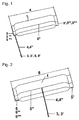
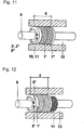
- the Fig. 1 shows the device consisting of a cut flat hose bag [1, 6] with a compressed air valve [3, 3 '] which is connected to a metal, plastic-coated valve extension [4,4 "], which is located on one of the transverse sides of the flat hose cushion and at
- the design as a flat hose cushion is achieved by producing pressure-tight closures at both ends (lateral sides) [5, 5 ', 5 "', 5""] and in longitudinal direction [5"].
- the flat hose cushion [1] is inserted in a circular manner between the wall opening and jacket pipe, cable duct and media pipe or multiple media pipe, multiple cable.
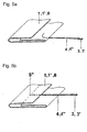
- the Fig. 2 shows one of the Fig. 1 similar device for longitudinal use in rectangular cable ducts or for sealing gaps in partition walls, wherein the compressed air valve [3, 3 '] after Fig. 6b can be attached to the longitudinal side [5 "] of the flat tube cushion.
- the Fig. 3 shows one of the Fig. 1 and 2 similar device, which has two compressed air valves [3, 3 '] with valve extension [4] and is suitable for filling the flat tubular bag with gaseous, powdered or liquid media. While the first compressed air valve is used for filling, the second compressed air valve [3, 3 '] can be used to discharge the compressed air during filling.
- Fig. 4 shows a similar device of Fig. 1, 2 and 3 which is limited in length [6] to the entire inner circumference of the wall breakthrough, casing tube, Lucaskanalohrs or the length of the gap in partitions and in the width [1 '] to be filled cavity to the media tube or the partition wall.
- Upper [2] and lower surface [2 '] of the flat tubular bag can be prefabricated partially or completely with a sealing tape [7], which may have elongated projections [7'].
- the full-surface application or stringing the Abdichtb species [7 "] on the flat hose cushion is advantageous when used in wall breakthroughs.
- Fig. 5a to 5h show perspectively various embodiments of a pressure-tight flat-tube cushion closure with valve, and in particular how the metal, plastic-coated valve extension [4] in the flat hose cushion [1, 1 ', 6] can be introduced.
- Fig. 5a shows a partial perspective view of the in Fig. 1 . 3 . 4 and 16a described end closure [1, 1 ', 6] on the transverse side of the flat tube pad manufactured from an overlapping folded composite foil. The end was shown here in the unlocked state to show the position of the special valve [4, 3, 3 '] on the pressure-tight closure.
- Fig. 5b shows a partial perspective view of the in Fig. 2 .
- the plastic-coated valve extension [4] of the special valve [3, 3 '] is inserted in the longitudinal welding [5 "] of the overlapping folded composite film of the flat tube cushion to the location of the special valve of the Fig. 2 inside the pressure-tight longitudinal welding [5 "] of the flat hose cushion [1].
- Fig. 5c shows a perspective view of the in Fig. 1 . 3 . 4 . 5a . 5d . 5g . 5h and 16a described Flachschlauchkissens [1, 1 ', 6] formed from a composite film with pressure-tight fasteners on the transverse sides [5, 5', 5 "] and the film overlap in the longitudinal direction [5"].
- the end closure [5, 5 ', 5 ", 5"'] produced by means of heat-sealing or high-frequency welding processes has a smooth design Fig. 5a with a composite film thickness of 250 to 600 .mu.m, accommodates an inserted special valve [4, 3, 3 '] Fig. 6a and with a circular application of a bending shear stress of the composite foil-plastic-metal compound of 100 - 120 N / cm withstand.
- Fig. 5d shows a perspective view of the in Fig. 1 . 3 and 4 described flat hose pad [1, 1 ', 6] with two, produced in heat-sealing or high-frequency welding process, pressure-tight fasteners [5, 5', 5 "] on the two transverse sides of the flat hose cushion and a pressure-tight welded metal, plastic-coated valve extension [4 '] which is connected in the interior of the flat hose cushion, with a perforated, flexible plastic hose extending over the entire length of the flat hose cushion [6], which serves for uniform distribution of the filling in the case of long flat hose cushions a passenger car compressed air valve [3, 3 '] for filling the flat tube pad with filling media [8, 8'] attached.
- the flat-tube cushion [1, 1 ', 6] has been shown here in the cut-open state in order to show the position of the valve extension [4, 4'] within the flat-tube cushion.
- Fig. 5e shows a perspective view of the in the FIGS. 1 . 3 . 4 . 5d and 16a for the circular application which is formed from a composite film with pressure-tight closures on the two transverse sides [5, 5 '] and from an overlap [5 "] in the longitudinal direction
- the end closure produced by means of heat-stamp welding [5, 5 '] has a honeycomb or corrugated design Fig. 5g and 5h on.
- the honeycomb or corrugated closure surface [5 ""] allows for increased flat-tube cushion inflation pressure and shear stress resistance of 120-140 N / cm.
- One or two special valves [4, 3, 3 '] can be welded into the end closure.
- Fig. 5f shows a perspective view of the in the Fig.
- the flat-tube cushion [1, 1 ', 6] which is formed from a composite film with pressure-tight closures on the transverse sides [5, 5', 5 ""] and an overlap [5 "] in the longitudinal direction
- the end closure produced by means of a hot-stamp welding process on the transverse sides [5, 5 ', 5 "] has a smooth, honeycomb-shaped or corrugated configuration and an additional metal or Kunststoffverpressung [5"'], which withstand longitudinal longitudinal application of the flat hose cushion additional internal overpressure shear forces In the overlap [ 5 "] of the composite foil, one or two special valves [4, 3, 3 '] can be welded.
- Fig. 5g shows a cross section of the Fig. 5c . 5e and 5f a pressure-tight end closure [5, 5 '] with a metal plastic-coated special valve [4, 4 ", 3, 3'] after Fig. 6a or 6b and a honeycomb-shaped or wavy configuration of the closure upper or lower surface [5 ""] under shear stress [18] with a flat-tube cushion filling pressure of ⁇ 2 bar.
- the end closure is shown here in the extended state as in longitudinal application as a lifting and sealing element for spaces in partitions.
- Fig. 5h shows a cross section of the Fig. 5g a pressure-tight end closure [5, 5 '] with plastic-metal compound at a flat hose pad filling pressure of ⁇ 4 bar.
- the pressure-tight end closure on the transverse side [5,5 '] has a plastic-coated, metal special valve [4, 4 ", 3, 3'] and a honeycomb-shaped or corrugated configuration of the closure upper or lower surface [5""]
- End closure is here shown in the bent state as in the circular application as a sealing element in pipe runs.
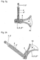
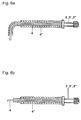
- the Fig. 6a and 6b show a perspective view of the in the Fig. 5a . 5c . 5d . 5e . 5g and 5h shown special valve in the bent state or in the Fig. 5b and 5f shown special valve in the straight state, consisting of a compressed air valve [3, 3 ', 3 "] with metallic valve extension [4], which is plastic-coated for mechanical thermic reasons of the connection between metal [4] and flat hose cushion [1] with PE, PUR or PA and as a bending protection of the metal valve extension [4 '] additionally comprises a heat-shrinkable tube [4 "].
- FIGS. 7 to 14 show different embodiments of in Fig. 1 . 3 . 4 and 16a described apparatus for the circular arrangement of the device as a sealing element in wall openings [10], smooth or corrugated liners (sleeve) [1o] or cable channels [11].
- Fig. 7 shows a cross section of in Fig. 1 . 4 .
- the device consists of one or two prefabricated flat hose cushions [1, 1 ', 6] with a metal compressed air valve [3, 3', 8, 8 "] which is provided with a plastic-coated valve extension [4, 4"].
- the Fig. 8 shows one of the Fig. 7 similar device, in which the flat tubular bag [1] for filling with liquid filling media [8 '] at each pressure-tight closure on the transverse sides [5, 5'] of Fig. 3 and 16b is equipped with a metal, plastic-coated valve extension [4, 4 "] and a compressed air valve [3 ']
- a valve adapter with shut-off valve can be used to drain off the liquid filling media.
- Fig. 9 is one of the Fig. 7 Similar design of the seal for multi-media pipes or multi-cable [12] shown in which each individual media tube and / or cable before filling the flat tubular bag [1, 6] outside the sealing with sealing tape [7 "'] wrapped and this winding then under the Flat hose cushion [1] is pushed with prefabricated sealing tape [7, 7 "]. After filling the flat hose cushion [1] via the compressed air valve [3, 3 ', 3 ", 4, 4"] and pressing the sealing tapes [7, 7'"], all cavities [13] are sealed under pressure gas and water tight.
- Fig. 10 shows one who Fig. 8 similar perspective view of the sealing device with brandabschottender additional function.
- sealing device is located in the center of the wall duct [10], around the media tube [9], multi-media tube [12] or the cable duct [11] wound band or hose with fire-barrier function [14].
- Fig. 11 shows one of the Fig. 8 Similar sealing device consisting of a flat hose cushion [1 '] with a width of 550 mm 3 or 4 The device is used for sealing cavities [13] for wall penetrations up to 600 mm in diameter or a particularly high, flexible, friction-resistant pressure seal between wall breakthrough [10], Jacket tube / cable duct [11] and the media tube [9] .Filling of the flat tube cushion [1 '] via the compressed air valves [3'] with liquid media [8 '] achieves an increased seal.
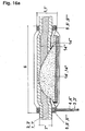
- Fig. 12 shows one who Fig. 10 or 11 similar perspective view of the sealing device with fire-barrier additional function, in which deviates from Fig. 11 and 16b in addition to the gas-tight, watertight and flame-retardant sealing of the intermediate space [13], a fire-sealing filling hose [14] or tape is wound over the media pipe [9] and the flat hose cushion [1 '], if necessary, after Fig. 16b with fire-barrier filling [14 '. 14 "] is filled.
- the Fig. 13 shows a cross section of in Fig. 1, 2 . 3, 4 . 5d . 7 . 9 and 16a shown fully circular arranged device for sealing in the jacket tube / conduit [11] or wall breakthrough [10] laid cable or multiple and / or conduit ducts [12].
- the device is as in Fig.
- the 0.5 to 2.5 bar gas- or watertight sealing of the jacket or cable duct pipe is by increasing the internal pressure by introducing air or a liquid through the compressed air valve [3] and pressing the sealing tape [7, 2] and the flexible sealing stars [15] achieved in the gusset.
- By subsequent pressure reduction is the pressure-voltage-deformation ratio of the flat tube cushion [1] in the elastic range.
- Fig. 14 shows a cross section of the view of Fig. 13 in which the flat hose cushion [1 "] is placed semicircularly around a large outer diameter cable / tube assembly [12] which is located in a jacket / conduit channel [11] or a wall opening [10] pressure-tight and watertight sealing of the cable / pipe assembly [12] in the cable duct / jacket pipe [11] or wall opening [10] by inserting the pipe / cable assembly into the sealing star [15], the sealing tape [2 , 2 ', 7] and the compression achieved by the flat-tube cushion [1 "].
- FIGS. 15a to 15b show various possible embodiments of in Fig. 13 and 14 described two-part sealing stars [15] for standard multi-tubes or multi-cable with defined outer diameter, which are used in the cable duct / jacket tube [11].
- Fig. 15a shows a cross section through an unclosed two-part sealing star [15, 15 '] for four pipes or cables.
- Fig. 15b shows a cross section through an unclosed two-part sealing star [15, 15 '] for five pipes or cables
- Fig. 16a and 16b show a perspective view of the ins Fig. 1-4 .
- 5d shown Flachschlauchkissens [1,1 ', 1 "', 6] in the cut state, the factory with a fire-barrier filling and a Brandabschottenden wrapping was provided.
- Fig. 16a shows a perspective view of the in Fig. 1 . 4 . 5d . 7 . 9-13 shown apparatus for fully circular arrangement in the jacket tube, cable duct pipe or in the wall opening.
- the device is as in Fig. 1 . 4 . 5d . 7 . 9-13 from a prefabricated flat hose cushion [1, 1 ', 6] with factory-integrated fire-barrier filling made of an elastic fire-barrier base polymer tape [14'] or a granulate [14 "] and a metal compressed air valve [3, 3 '] Fig. 6a with plastic-coated valve extension [4, 4 "].
- the ends of the flat-tube bag were closed by a suitable process to form corrugated, honeycomb-shaped [5""] or smooth [5, 5 '] closures shear resistant [18] to 5 bar filling pressure.
- conduit or wall breakthrough in the middle of the device was a pre-assembled, not permanently bonded to the components sealing tape [2, 2 ', 7, 7'] and on both outer sides of a fire-barrier sealing tape [14 "'] around the flat hose cushion [1, 1', 6]
- the gas- and water-tight sealing of the jacket or cable duct pipe is achieved by increasing the filling pressure by introducing air or a liquid via the compressed air valve [3, 3 '] and compression of the sealing band [7, 2] or the flexible sealing stars in the gusset achieved by subsequent pressure reduction, the pressure-voltage-deformation ratio of the flat tube pad [1] is in the elastic range.
- Fig. 16b shows a perspective view of the in Fig. 1-4 . 5d shown device in the cut state for longitudinal application in the rectangular cable duct or in wall ducts with laid cables / media tubes.
- the device is as in Fig. 1-5 . 5d and 16a from a prefabricated flat hose cushion [1, 1 ', 6] with factory-integrated fire-barrier filling [14', 14 "] and external fire-barrier tape winding [14 '"'] and gas-tight and waterproof sealing tape winding [2, 2 ', 7, 7 '] and one or two plastic-coated metal Compressed air valves [3, 3 ', 4, 4 "] Fig.
- Fig. 17 shows a perspective view of the in Fig. 2 . 3 . 4 and 16b rectangularly arranged device for sealing the cables and / or pipes laid in the cable duct [11] or between separating / partitions [9].
- the device is as in Fig. 2 . 3 . 4 and 16b described prefabricated flat hose cushion [1, 1 ', 6] with a compressed air valve [3, 3'] after Fig. 6b , which is provided with a plastic-coated valve extension [4.4 "] at the longitudinal weld [5"].
- the ends [5, 5 ', 5 "', 5""] of the flat-tube cushion were closed by means of a suitable method to internal over-pressure shear-resistant closures [5"', 5 "”].
- a prefabricated sealing tape [7, 7 ', 7 "] not permanently bonded to the components was wound around the flat hose cushion [1, 1', 6].
- a two-part sealing block [15 "] or slotted rows of single blocks [16] with anchorages to the outer sealing block [15] is used to seal the cables and / or pipes [9] laid in the cable duct or between partition walls [11] '] / Single block sides [16'] and anchors, recesses on the inner sealing block sides [15 "", 16 "] and on the outer side of the cable / pipe, blind plug [17] or the cable / pipe adapter [17 '].
- the tensile / compression-resistant and fire-resistant 0.5 bar gas or watertight sealing of the cable duct [11] is achieved by increasing the internal pressure by introducing air or a liquid via the compressed air valve [3, 3 '] and pressing the sealing tape [7 ] and the sealing block [15, 16, 17] achieved in the gussets.
- By subsequent pressure reduction is the pressure-strain-deformation ratio of the flat tube cushion [1, 1 ', 6] in the elastic region.
- Fig. 18 shows a perspective view of the in Fig. 17 described sealing device made of a two-part sealing block [15 "] with juxtaposed single blocks [16] shown in pulled-apart state to show the position of the anchors on the upper and lower sides [15"'] of the sealing block and single block.
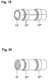
- Fig. 19 shows a perspective view of the in Fig. 17 slotted cable / pipe adapter [17 '] with anchors on the outside [17 "] for absorbing tensile and shear forces.
- Fig. 20 shows a perspective view of the in Fig. 17 Blind stopper [17] with anchors on the outside [17 "] for use as a sealing element for uncovered sealing or single blocks.
Landscapes
- Engineering & Computer Science (AREA)
- General Engineering & Computer Science (AREA)
- Mechanical Engineering (AREA)
- Architecture (AREA)
- Civil Engineering (AREA)
- Structural Engineering (AREA)
- Rigid Pipes And Flexible Pipes (AREA)
Claims (22)
- Dispositif de fermeture étanche aux gaz et à l'eau sous pression et/ou coupe-feu de cavités dans les percées murales (10), tubes d'enveloppe (11), conduits de câbles (11, 11', 11") qui sont garnis de tubes de fluide comme par exemple gaz, eau [résiduaire], chauffage urbain, etc. ou de conduits (9), le dispositif étant constitué d'un coussin en forme de tuyau plat (1) mis à dimension en longueur (6) et largeur (1') pour l'application prévue, qui présente des fermetures (5, 5', 5"', 5"") résistantes à la pression sur le côté longitudinal (5") et les côtés transversaux et qui est rempli au moyen d'au moins une valve (3, 3') métallique plastifiée avec rallonge de vanne (4, 4', 4") et rendu étanche en plus à l'extérieur du coussin en forme de tuyau plat (1) par une bande d'étanchéité étanche aux gaz et à l'eau sous pression,
caractérisé par
un agencement (13) à deux couches, circulaire, du coussin en forme de tuyau plat (1), la valve (3', 3") étant reliée à l'intérieur du coussin en forme de tuyau plat, sur toute la longueur du coussin en forme de tuyau plat, à un tuyau en plastique (4') perforé. - Dispositif selon la revendication 1,
caractérisé en ce
que les cavités sont garnies de tubes de fluide lisses ou ondulés. - Dispositif selon la revendication 1 ou 2,
caractérisé en ce
que le coussin en forme de tuyau plat (1) est rempli de fluides gazeux (8), pulvérisés ou liquides (8') ou pouvant durcir ou se dissoudre de manière flexible (8"). - Dispositif selon une des revendications précédentes,
caractérisé en ce
que le coussin en forme de tuyau plat (1, 1') peut être fabriqué dans la longueur (6) en fonction de la circonférence de la percée murale (10), du tube d'enveloppe/conduit de câbles (11, 11') ou de l'espace intermédiaire dans le cas de cloisons de séparation (11") et dans la largeur (1') en fonction de la taille de la cavité (13) à rendre étanche, dans des largeurs allant jusqu'à 550 mm pour, selon le cas d'application, obtenir une étanchéité de la cavité avec une faible pression de remplissage de 2,0 à 5,0 bars et une contrainte de pression transversale sensiblement réduite du tube de fluide (9) de 20 à ≤ 90 N/cm2, sans influencer les propriétés d'écoulement des fluides par suite d'une bosselure du tube de fluide. - Dispositif selon une des revendications précédentes,
caractérisé en ce
que les fermetures (5, 5') résistantes à la pression du coussin en forme de tuyau plat possèdent en standard une structure lisse (5, 5') et pour une résistance au cisaillement par surpression interne (18) plus élevée, une structure alvéolaire ou ondulée (5""). - Dispositif selon une des revendications précédentes,
caractérisé en ce
que la valve est constituée d'une valve pneumatique métallique (3, 3', 3") avec une rallonge de valve (4, 4") métallique plastifiée, le revêtement plastique étant dans un matériau identique à celui du coussin en forme de tuyau, par exemple en PE, PUR, PA ou un matériau équivalent pour le procédé de soudage, ce qui permet d'atteindre une durée de vie plus longue du dispositif par recharge pendant les cycles de maintenance. - Dispositif selon une des revendications précédentes,
caractérisé en ce
que la valve (3, 3', 3") est disposée, selon le domaine d'application, sur le côté transversal (5, 5') ou sur le côté longitudinal (5") du coussin en forme de tuyau plat (1, 1', 6) et réalisée sous la forme d'une valve pneumatique de voiture, de moto (3) ou d'une valve spéciale (3', 3") et peut être remplie de fluides de remplissage gazeux (8) ou pulvérisés ou liquides (8'). - Dispositif selon les revendications 1 à 6,
caractérisé en ce
que le coussin en forme de tuyau plat (1, 1', 6) est disposé, dans le domaine d'application en tant qu'élément individuel, en deux couches en forme de cercle dans la circonférence de la percée murale (10), du tube de fluide (11) ou tube de conduit (11, 11'), la valve (3, 3', 3") se trouvant à une extrémité (5, 5', 5"") du coussin en forme de tuyau plat (1, 1', 6) et une valve spéciale (3, 3', 3") flexible dans toutes les directions, qui peut être placée à l'abri dans l'espace intermédiaire de l'étanchéité (13), étant réalisée par la rallonge de valve métallique plastifiée (4, 4"). - Dispositif selon une des revendications précédentes,
caractérisé en ce
que le coussin en forme de tuyau plat (1, 1', 6) contient, pour une étanchéité destinée à être remplie de fluides pulvérisés ou liquides (8') ou d'une matière de remplissage pouvant durcir et/ou se dissoudre de manière flexible (8"), deux valves (3', 3") pour le remplissage sans bulles d'air du coussin en forme de tuyau plat. - Dispositif selon une des revendications 1 à 5 et 8,
caractérisé en ce
que le coussin en forme de tuyau plat (1, 1', 6) présente en outre en direction longitudinale ou transversale une bande d'étanchéité élastique, adhésive de manière (non) durable, avec une armature en fibres synthétiques (7) en une rangée d'enroulement ou des bandes d'étanchéité juxtaposées (7"). - Dispositif selon une des revendications 1 à 5 et 8 à 10,
caractérisé en ce
que lors de l'étanchéification de percées murales (10), tubes d'enveloppe (11), conduits de câbles (11, 11', 11"), tubes de fluide (9) et faisceaux de câbles (12), un enroulement de bande d'étanchéité (7, 7", 7"') avec/sans feuille de séparation est utilisé au niveau des points de contact de percées murales (10), du coussin en forme de tuyau plat (1, 1'), de conduits de câbles (11, 11', 11") ou de tubes de fluide multiples/câbles multiples (12), et une étoile d'étanchéité à plasticité permanente (15, 15'), un bloc d'étanchéité (15", 15"', 15""), un module d'étanchéité (16, 16') ou un enroulement de bande d'étanchéité (7) se trouve dans le coin. - Dispositif selon la revendication 10 ou 11,
caractérisé en ce
que dans le cas de la bande d'étanchéité (7) pour l'obturation étanche aux gaz et à l'eau sous pression, selon le domaine d'application, l'enroulement de bande d'étanchéité (7', 7") se compose d'un mélange de vaseline-petrolatum à élasticité permanente dans la plage de température de -30 °C à +70 °C et résistant à la pression jusqu'à 100 N/cm2, modifié par des charges de polymères, sable quartzeux ou farine de schiste ou d'un mélange petrolatum-bitume ou de gels ou d'une mousse dure de PUR à cellules fermées qui possède une épaisseur d'environ 1,0 à 3 mm et présente une largeur de 40 à 80 % de la largeur du coussin en forme de tuyau plat (1) en recouvrant partiellement (7) ou totalement (7") la surface du coussin en forme de tuyau plat. - Dispositif selon une des revendications 10 à 12,
caractérisé en ce
que pour l'obturation étanche aux gaz et à l'eau sous pression avec fonction coupe-feu, la bande d'étanchéité (7) située au milieu et l'enroulement de bande d'étanchéité (7', 7") pour tube de fluide et câble se composent d'une bande textile à élasticité permanente, résistante à la pression jusqu'à 100 N/cm2, réalisée à partir d'une armature en fibres synthétiques (7) imputrescible, qui se compose des deux côtés d'un mélange de vaseline-petrolatum modifié par des charges de polymères, sable quartzeux ou farine de schiste ou d'une mousse dure de PUR à cellules fermées sur l'armature en fibres synthétiques (7), qui présente une épaisseur de 2,0 à environ 3,0 mm et recouvre dans la largeur entre 20 et 40 % de la surface du coussin en forme de tuyau plat (1) et des tubes de fluide/câbles, les surfaces de bord restantes étant recouvertes de bandes coupe-feu (14'). - Dispositif selon les revendications 12 et 13,
caractérisé en ce
que les bandes d'étanchéité (7, 7', 7",7"') sont enveloppées d'un côté ou des deux côtés d'une feuille de séparation souple extensible. - Dispositif selon une des revendications 10 à 12 et 14,
caractérisé en ce
que les bandes d'étanchéité (6) composées d'une armature en fibres synthétiques imputrescible sont fabriquées à partir d'un matériau extensible en direction longitudinale et transversale, tel que coton, chanvre, filaments de polyester-polypropylène, etc. - Dispositif selon une des revendications 10 à 13,
caractérisé en ce
que les bandes d'étanchéité (6) sont réalisées à partir d'une bande de mousse dure à cellules fermées, de préférence en PUR ou silicone, avec revêtement adhésif d'un côté. - Dispositif selon une des revendications précédentes,
caractérisé par
un garnissage avec des tubes de fluide multiples/câbles multiples (12), le dispositif comprenant un enroulement de bande d'étanchéité (7"') ou une étoile d'étanchéité/un bloc d'étanchéité (15, 16) qui est introduit entre les différents câbles ou tubes à rendre étanches. - Dispositif selon la revendication 17,
caractérisé en ce
que l'étoile d'étanchéité (15), le bloc d'étanchéité (15", 15"', 15""), le module individuel de bloc d'étanchéité (16, 16', 16") est réalisé(e) en deux parties et non fermé (15') ou fermé et fendu dans un matériau modifiable en direction transversale, sans halogènes, ininflammable, comme la mousse dure de PUR (polyuréthane). - Dispositif selon une des revendications précédentes,
caractérisé par
un remplissage coupe-feu (14', 14"), le cas échéant intégré, du coussin en forme de tuyau plat pour la fermeture coupe-feu supplémentaire de cavités. - Dispositif selon une des revendications précédentes,
caractérisé en ce
que le dispositif est également rendu étanche à l'extérieur du coussin en forme de tuyau plat (1) par une bande coupe-feu (14, 14', 14") pour la fermeture coupe-feu supplémentaire de cavités. - Dispositif selon la revendication 19 ou 20,
caractérisé en ce
qu'un agent coupe-feu (14) se trouve devant le coussin en forme de tuyau plat ou dans la cavité de la traversée de mur (13), derrière ou entre deux coussins en forme de tuyau plat (1, 1') dans une bande tubulaire (14) et est réalisé sous la forme d'une bande élastique coupe-feu (14') ou d'un granulat coupe-feu (14"). - Dispositif selon la revendication 19, 20 ou 21,
caractérisé en ce
que le ou les agent(s) coupe-feu à l'intérieur et à l'extérieur du coussin en forme de tuyau plat (14'), la bande d'étanchéité coupe-feu (7) située autour du tube de fluide/câble constituée d'une bande élastique souple ou, dans le tuyau (14'), d'un granulat de granulométrie 2 à 3 mm et les étoiles d'étanchéité (15, 15'), blocs d'étanchéité (15", 15"', 15""), module individuel de bloc d'étanchéité (16, 16', 16") ainsi que les bouchons d'obturation et de tube (17, 17') sont réalisés à partir d'un profilé extrudé dans un matériau qui est formé d'un polymère de base et d'additifs expansibles.
Applications Claiming Priority (1)
| Application Number | Priority Date | Filing Date | Title |
|---|---|---|---|
| DE102006027888 | 2006-06-17 |
Publications (2)
| Publication Number | Publication Date |
|---|---|
| EP1867904A1 EP1867904A1 (fr) | 2007-12-19 |
| EP1867904B1 true EP1867904B1 (fr) | 2012-11-14 |
Family
ID=38335547
Family Applications (1)
| Application Number | Title | Priority Date | Filing Date |
|---|---|---|---|
| EP06017206A Not-in-force EP1867904B1 (fr) | 2006-06-17 | 2006-08-18 | Dispositif d'étanchéité pour un passage de conduite à travers une ouverture murale, un tuyau ou une conduite |
Country Status (1)
| Country | Link |
|---|---|
| EP (1) | EP1867904B1 (fr) |
Cited By (7)
| Publication number | Priority date | Publication date | Assignee | Title |
|---|---|---|---|---|
| EP3056621A1 (fr) | 2015-02-11 | 2016-08-17 | Fibre Optics CT GmbH, Consulting & Testing | Dispositif de protection réutilisable contre l'infiltration d'eau |
| EP3263964A1 (fr) | 2016-07-01 | 2018-01-03 | Fibre Optics CT GmbH, Consulting & Testing | Joint d'etancheite contre la conduction d'eau |
| DE202017006970U1 (de) | 2017-10-19 | 2019-01-30 | Roland Wolf | Mehrweg-Abdichtung |
| EP3474402A1 (fr) | 2017-10-19 | 2019-04-24 | Roland Wolf | Dispositif d'étanchéité réutilisable |
| EP4140708A1 (fr) | 2021-08-25 | 2023-03-01 | Roland Wolf | Dispositif et procédé de fabrication d'un tuyau en feuille à partir d'une bande de feuille selon le procédé de soudage avec conformateur |
| EP4488559A1 (fr) | 2023-07-07 | 2025-01-08 | Roland Wolf | Élément d'étanchéité réutilisable |
| DE102023117934A1 (de) | 2023-07-07 | 2025-01-09 | Roland Wolf | Wiederverwendbares Abdichtelement |
Families Citing this family (5)
| Publication number | Priority date | Publication date | Assignee | Title |
|---|---|---|---|---|
| CN108167482A (zh) * | 2018-01-18 | 2018-06-15 | 深圳市万居科技股份有限公司 | 一种防火止回阀 |
| US12492550B2 (en) * | 2023-04-18 | 2025-12-09 | Dupont Safety & Construction, Inc. | Foam envelope for sealing large volumes |
| US12559935B2 (en) * | 2023-04-18 | 2026-02-24 | Dupont Safety & Construction, Inc. | Foam envelope for sealing large volumes |
| US12454822B2 (en) * | 2023-04-18 | 2025-10-28 | Ddp Specialty Electronic Materials Us, Llc | Foam envelope for sealing large volumes |
| US12492551B2 (en) * | 2023-04-18 | 2025-12-09 | Dupont Safety & Construction, Inc. | Foam envelope for sealing large volumes |
Family Cites Families (9)
| Publication number | Priority date | Publication date | Assignee | Title |
|---|---|---|---|---|
| DE41005C (de) | 1887-03-12 | 1887-10-07 | W. BAUR in Brooklyn, Staat New-York, V. St. A | Neuerung an Filterpressen |
| US3038732A (en) * | 1958-04-07 | 1962-06-12 | Texas Pipe Line Company | Inflatable seal bushing for pipeline casing |
| GB8333722D0 (en) * | 1983-12-19 | 1984-01-25 | Raychem Gmbh | Expansible seal |
| GB9201069D0 (en) * | 1992-01-17 | 1992-03-11 | Raychem Sa Nv | Environmental sealing |
| DE19736494A1 (de) | 1997-08-22 | 1999-02-25 | Hauff Technik Gmbh & Co Kg | Dichtpackung zum Einsetzen in eine Maueröffnung zwecks Durchführen von Leitungen |
| DE19803958C1 (de) | 1998-02-03 | 1999-05-06 | Hauff Technik Gmbh & Co Kg | Wanddurchführung zum Einsetzen in ein durch eine Mauer hindurchführendes Durchgangsloch |
| WO2001090607A2 (fr) * | 2000-05-23 | 2001-11-29 | Tdm Industries, Inc. | Element formant un joint souple |
| DE10341005A1 (de) * | 2003-09-05 | 2005-03-31 | Fibre Optics Ct Gmbh | Abdicht-, Hebe- und/oder Sicherungsvorrichtung |
| ATE403964T1 (de) * | 2005-01-28 | 2008-08-15 | Fibre Optics Ct Gmbh Consultin | Wiederverwendbare abdicht-, hebe- und/oder sicherungsvorrichtung |
-
2006
- 2006-08-18 EP EP06017206A patent/EP1867904B1/fr not_active Not-in-force
Cited By (13)
| Publication number | Priority date | Publication date | Assignee | Title |
|---|---|---|---|---|
| EP3056621A1 (fr) | 2015-02-11 | 2016-08-17 | Fibre Optics CT GmbH, Consulting & Testing | Dispositif de protection réutilisable contre l'infiltration d'eau |
| WO2016128435A1 (fr) | 2015-02-11 | 2016-08-18 | Fibre Optics Ct Gmbh Consulting & Testing | Dispositif réutilisable de protection contre le passage d'eau |
| CN107208414A (zh) * | 2015-02-11 | 2017-09-26 | R·沃尔夫 | 可重复使用的防水传导的防护装置 |
| EP3263964A1 (fr) | 2016-07-01 | 2018-01-03 | Fibre Optics CT GmbH, Consulting & Testing | Joint d'etancheite contre la conduction d'eau |
| WO2018001896A1 (fr) | 2016-07-01 | 2018-01-04 | Roland Wolf | Étanchéification contre l'infiltration d'eau |
| DE202017006970U1 (de) | 2017-10-19 | 2019-01-30 | Roland Wolf | Mehrweg-Abdichtung |
| EP3474402A1 (fr) | 2017-10-19 | 2019-04-24 | Roland Wolf | Dispositif d'étanchéité réutilisable |
| DE202018006655U1 (de) | 2017-10-19 | 2022-01-12 | Roland Wolf | Mehrweg-Abdichtung |
| EP4140708A1 (fr) | 2021-08-25 | 2023-03-01 | Roland Wolf | Dispositif et procédé de fabrication d'un tuyau en feuille à partir d'une bande de feuille selon le procédé de soudage avec conformateur |
| DE102021121988A1 (de) | 2021-08-25 | 2023-03-02 | Roland Wolf | Vorrichtung zum Herstellen von Folienschlauch aus einem Folienband im Formschulter-Schweißverfahren |
| DE102021121988B4 (de) | 2021-08-25 | 2024-06-06 | Roland Wolf | Vorrichtung zum Herstellen von Folienschlauch aus einem Folienband im Formschulter-Schweißverfahren |
| EP4488559A1 (fr) | 2023-07-07 | 2025-01-08 | Roland Wolf | Élément d'étanchéité réutilisable |
| DE102023117934A1 (de) | 2023-07-07 | 2025-01-09 | Roland Wolf | Wiederverwendbares Abdichtelement |
Also Published As
| Publication number | Publication date |
|---|---|
| EP1867904A1 (fr) | 2007-12-19 |
Similar Documents
| Publication | Publication Date | Title |
|---|---|---|
| DE69220786T2 (de) | Umgebungsabdichtung | |
| EP3256656B1 (fr) | Dispositif de protection réutilisable contre l'infiltration d'eau | |
| DE69303610T2 (de) | Abdichtungsvorrichtung gegen umwelteinflüsse | |
| EP1867904B1 (fr) | Dispositif d'étanchéité pour un passage de conduite à travers une ouverture murale, un tuyau ou une conduite | |
| EP0952382B1 (fr) | Conduite flexible | |
| DE1525658C3 (de) | Wärmeisoliertes Leitungsrohr | |
| EP2427693A2 (fr) | Coque isolante | |
| DE102009061082B4 (de) | System und Verfahren zum Einbau eines Rohrs in einer Wandöffnung | |
| EP3474402A1 (fr) | Dispositif d'étanchéité réutilisable | |
| EP2314903B1 (fr) | Système et procédé destinés à l'intégration d'un tuyau dans une ouverture de mur ainsi que résine comprimée expansée et manchette correspondante | |
| EP0634602A1 (fr) | Tuyau isolé thermiquement | |
| EP0385141B1 (fr) | Gaine thermorétrécissable | |
| EP1909012A2 (fr) | Manchette isolante | |
| DE4105625C2 (de) | Abdichtung für einen Zwischenraum zwischen einem Kabelkanal und einer darin verlegten Leitung, die aufblähbar und gasundurchlässig ist | |
| EP3464741A1 (fr) | Cordon d'étanchéité destiné à assurer l'étanchéité d'un joint entre des éléments de construction ainsi que procédé de fabrication d'un tel cordon d'étanchéité | |
| EP2113702B1 (fr) | Embrayage destiné à la liaison de deux extrémités de tuyaux, doté d'une étanchéité de source secondaire | |
| DE9407409U1 (de) | Flexibles wärmeisoliertes Leitungsrohr | |
| DE102013224027B4 (de) | Durchführungsvorrichtung für Leitungen, insbesondere Hauseinführung | |
| AT510139B1 (de) | Vorrichtung zum abdichten und fixieren eines in ein bohrloch eingesetzten rohres im bohrloch | |
| DE102014009318B4 (de) | System und Verfahren zum Einbau eines Rohres in einer Wandöffnung sowie dessen Verwendung | |
| DE60023684T2 (de) | Neue brandschutzvorrichtung und ihre verwendung | |
| DE10341005A1 (de) | Abdicht-, Hebe- und/oder Sicherungsvorrichtung | |
| EP1686670B1 (fr) | Dispositif réutilisable d'étanchéité, de levage et/ou de sécurité | |
| EP3478997A1 (fr) | Étanchéification contre l'infiltration d'eau | |
| CH703167A2 (de) | Verbundrohr. |
Legal Events
| Date | Code | Title | Description |
|---|---|---|---|
| PUAI | Public reference made under article 153(3) epc to a published international application that has entered the european phase |
Free format text: ORIGINAL CODE: 0009012 |
|
| AK | Designated contracting states |
Kind code of ref document: A1 Designated state(s): AT BE BG CH CY CZ DE DK EE ES FI FR GB GR HU IE IS IT LI LT LU LV MC NL PL PT RO SE SI SK TR |
|
| AX | Request for extension of the european patent |
Extension state: AL BA HR MK YU |
|
| 17P | Request for examination filed |
Effective date: 20080619 |
|
| 17Q | First examination report despatched |
Effective date: 20080728 |
|
| AKX | Designation fees paid |
Designated state(s): AT BE BG CH CY CZ DE DK EE ES FI FR GB GR HU IE IS IT LI LT LU LV MC NL PL PT RO SE SI SK TR |
|
| GRAP | Despatch of communication of intention to grant a patent |
Free format text: ORIGINAL CODE: EPIDOSNIGR1 |
|
| GRAS | Grant fee paid |
Free format text: ORIGINAL CODE: EPIDOSNIGR3 |
|
| GRAA | (expected) grant |
Free format text: ORIGINAL CODE: 0009210 |
|
| AK | Designated contracting states |
Kind code of ref document: B1 Designated state(s): AT BE BG CH CY CZ DE DK EE ES FI FR GB GR HU IE IS IT LI LT LU LV MC NL PL PT RO SE SI SK TR |
|
| REG | Reference to a national code |
Ref country code: GB Ref legal event code: FG4D Free format text: NOT ENGLISH |
|
| REG | Reference to a national code |
Ref country code: CH Ref legal event code: EP Ref country code: AT Ref legal event code: REF Ref document number: 584192 Country of ref document: AT Kind code of ref document: T Effective date: 20121115 |
|
| REG | Reference to a national code |
Ref country code: IE Ref legal event code: FG4D Free format text: LANGUAGE OF EP DOCUMENT: GERMAN |
|
| REG | Reference to a national code |
Ref country code: DE Ref legal event code: R096 Ref document number: 502006012201 Country of ref document: DE Effective date: 20130110 |
|
| REG | Reference to a national code |
Ref country code: NL Ref legal event code: VDEP Effective date: 20121114 |
|
| REG | Reference to a national code |
Ref country code: LT Ref legal event code: MG4D |
|
| PG25 | Lapsed in a contracting state [announced via postgrant information from national office to epo] |
Ref country code: ES Free format text: LAPSE BECAUSE OF FAILURE TO SUBMIT A TRANSLATION OF THE DESCRIPTION OR TO PAY THE FEE WITHIN THE PRESCRIBED TIME-LIMIT Effective date: 20130225 Ref country code: SE Free format text: LAPSE BECAUSE OF FAILURE TO SUBMIT A TRANSLATION OF THE DESCRIPTION OR TO PAY THE FEE WITHIN THE PRESCRIBED TIME-LIMIT Effective date: 20121114 Ref country code: LT Free format text: LAPSE BECAUSE OF FAILURE TO SUBMIT A TRANSLATION OF THE DESCRIPTION OR TO PAY THE FEE WITHIN THE PRESCRIBED TIME-LIMIT Effective date: 20121114 Ref country code: FI Free format text: LAPSE BECAUSE OF FAILURE TO SUBMIT A TRANSLATION OF THE DESCRIPTION OR TO PAY THE FEE WITHIN THE PRESCRIBED TIME-LIMIT Effective date: 20121114 |
|
| PG25 | Lapsed in a contracting state [announced via postgrant information from national office to epo] |
Ref country code: SI Free format text: LAPSE BECAUSE OF FAILURE TO SUBMIT A TRANSLATION OF THE DESCRIPTION OR TO PAY THE FEE WITHIN THE PRESCRIBED TIME-LIMIT Effective date: 20121114 Ref country code: PT Free format text: LAPSE BECAUSE OF FAILURE TO SUBMIT A TRANSLATION OF THE DESCRIPTION OR TO PAY THE FEE WITHIN THE PRESCRIBED TIME-LIMIT Effective date: 20130314 Ref country code: PL Free format text: LAPSE BECAUSE OF FAILURE TO SUBMIT A TRANSLATION OF THE DESCRIPTION OR TO PAY THE FEE WITHIN THE PRESCRIBED TIME-LIMIT Effective date: 20121114 Ref country code: LV Free format text: LAPSE BECAUSE OF FAILURE TO SUBMIT A TRANSLATION OF THE DESCRIPTION OR TO PAY THE FEE WITHIN THE PRESCRIBED TIME-LIMIT Effective date: 20121114 Ref country code: GR Free format text: LAPSE BECAUSE OF FAILURE TO SUBMIT A TRANSLATION OF THE DESCRIPTION OR TO PAY THE FEE WITHIN THE PRESCRIBED TIME-LIMIT Effective date: 20130215 |
|
| PG25 | Lapsed in a contracting state [announced via postgrant information from national office to epo] |
Ref country code: BG Free format text: LAPSE BECAUSE OF FAILURE TO SUBMIT A TRANSLATION OF THE DESCRIPTION OR TO PAY THE FEE WITHIN THE PRESCRIBED TIME-LIMIT Effective date: 20130214 Ref country code: SK Free format text: LAPSE BECAUSE OF FAILURE TO SUBMIT A TRANSLATION OF THE DESCRIPTION OR TO PAY THE FEE WITHIN THE PRESCRIBED TIME-LIMIT Effective date: 20121114 Ref country code: DK Free format text: LAPSE BECAUSE OF FAILURE TO SUBMIT A TRANSLATION OF THE DESCRIPTION OR TO PAY THE FEE WITHIN THE PRESCRIBED TIME-LIMIT Effective date: 20121114 Ref country code: CZ Free format text: LAPSE BECAUSE OF FAILURE TO SUBMIT A TRANSLATION OF THE DESCRIPTION OR TO PAY THE FEE WITHIN THE PRESCRIBED TIME-LIMIT Effective date: 20121114 Ref country code: EE Free format text: LAPSE BECAUSE OF FAILURE TO SUBMIT A TRANSLATION OF THE DESCRIPTION OR TO PAY THE FEE WITHIN THE PRESCRIBED TIME-LIMIT Effective date: 20121114 |
|
| PG25 | Lapsed in a contracting state [announced via postgrant information from national office to epo] |
Ref country code: IT Free format text: LAPSE BECAUSE OF FAILURE TO SUBMIT A TRANSLATION OF THE DESCRIPTION OR TO PAY THE FEE WITHIN THE PRESCRIBED TIME-LIMIT Effective date: 20121114 Ref country code: RO Free format text: LAPSE BECAUSE OF FAILURE TO SUBMIT A TRANSLATION OF THE DESCRIPTION OR TO PAY THE FEE WITHIN THE PRESCRIBED TIME-LIMIT Effective date: 20121114 Ref country code: NL Free format text: LAPSE BECAUSE OF FAILURE TO SUBMIT A TRANSLATION OF THE DESCRIPTION OR TO PAY THE FEE WITHIN THE PRESCRIBED TIME-LIMIT Effective date: 20121114 |
|
| PLBE | No opposition filed within time limit |
Free format text: ORIGINAL CODE: 0009261 |
|
| STAA | Information on the status of an ep patent application or granted ep patent |
Free format text: STATUS: NO OPPOSITION FILED WITHIN TIME LIMIT |
|
| 26N | No opposition filed |
Effective date: 20130815 |
|
| PG25 | Lapsed in a contracting state [announced via postgrant information from national office to epo] |
Ref country code: CY Free format text: LAPSE BECAUSE OF FAILURE TO SUBMIT A TRANSLATION OF THE DESCRIPTION OR TO PAY THE FEE WITHIN THE PRESCRIBED TIME-LIMIT Effective date: 20121114 |
|
| REG | Reference to a national code |
Ref country code: DE Ref legal event code: R097 Ref document number: 502006012201 Country of ref document: DE Effective date: 20130815 |
|
| BERE | Be: lapsed |
Owner name: FIBRE OPTICS CT GMBH, CONSULTING & TESTING Effective date: 20130831 |
|
| REG | Reference to a national code |
Ref country code: CH Ref legal event code: PL |
|
| PG25 | Lapsed in a contracting state [announced via postgrant information from national office to epo] |
Ref country code: MC Free format text: LAPSE BECAUSE OF FAILURE TO SUBMIT A TRANSLATION OF THE DESCRIPTION OR TO PAY THE FEE WITHIN THE PRESCRIBED TIME-LIMIT Effective date: 20121114 Ref country code: CH Free format text: LAPSE BECAUSE OF NON-PAYMENT OF DUE FEES Effective date: 20130831 Ref country code: LI Free format text: LAPSE BECAUSE OF NON-PAYMENT OF DUE FEES Effective date: 20130831 |
|
| REG | Reference to a national code |
Ref country code: IE Ref legal event code: MM4A |
|
| PG25 | Lapsed in a contracting state [announced via postgrant information from national office to epo] |
Ref country code: BE Free format text: LAPSE BECAUSE OF NON-PAYMENT OF DUE FEES Effective date: 20130831 |
|
| PG25 | Lapsed in a contracting state [announced via postgrant information from national office to epo] |
Ref country code: IE Free format text: LAPSE BECAUSE OF NON-PAYMENT OF DUE FEES Effective date: 20130818 |
|
| REG | Reference to a national code |
Ref country code: AT Ref legal event code: MM01 Ref document number: 584192 Country of ref document: AT Kind code of ref document: T Effective date: 20130818 |
|
| PG25 | Lapsed in a contracting state [announced via postgrant information from national office to epo] |
Ref country code: AT Free format text: LAPSE BECAUSE OF NON-PAYMENT OF DUE FEES Effective date: 20130818 |
|
| PG25 | Lapsed in a contracting state [announced via postgrant information from national office to epo] |
Ref country code: TR Free format text: LAPSE BECAUSE OF FAILURE TO SUBMIT A TRANSLATION OF THE DESCRIPTION OR TO PAY THE FEE WITHIN THE PRESCRIBED TIME-LIMIT Effective date: 20121114 |
|
| PG25 | Lapsed in a contracting state [announced via postgrant information from national office to epo] |
Ref country code: LU Free format text: LAPSE BECAUSE OF NON-PAYMENT OF DUE FEES Effective date: 20130818 Ref country code: HU Free format text: LAPSE BECAUSE OF FAILURE TO SUBMIT A TRANSLATION OF THE DESCRIPTION OR TO PAY THE FEE WITHIN THE PRESCRIBED TIME-LIMIT; INVALID AB INITIO Effective date: 20060818 |
|
| REG | Reference to a national code |
Ref country code: FR Ref legal event code: PLFP Year of fee payment: 10 |
|
| PG25 | Lapsed in a contracting state [announced via postgrant information from national office to epo] |
Ref country code: IS Free format text: LAPSE BECAUSE OF FAILURE TO SUBMIT A TRANSLATION OF THE DESCRIPTION OR TO PAY THE FEE WITHIN THE PRESCRIBED TIME-LIMIT Effective date: 20121114 |
|
| REG | Reference to a national code |
Ref country code: FR Ref legal event code: PLFP Year of fee payment: 11 |
|
| PGFP | Annual fee paid to national office [announced via postgrant information from national office to epo] |
Ref country code: DE Payment date: 20160822 Year of fee payment: 11 Ref country code: GB Payment date: 20160819 Year of fee payment: 11 |
|
| PGFP | Annual fee paid to national office [announced via postgrant information from national office to epo] |
Ref country code: FR Payment date: 20160822 Year of fee payment: 11 |
|
| REG | Reference to a national code |
Ref country code: DE Ref legal event code: R119 Ref document number: 502006012201 Country of ref document: DE |
|
| GBPC | Gb: european patent ceased through non-payment of renewal fee |
Effective date: 20170818 |
|
| REG | Reference to a national code |
Ref country code: FR Ref legal event code: ST Effective date: 20180430 |
|
| PG25 | Lapsed in a contracting state [announced via postgrant information from national office to epo] |
Ref country code: DE Free format text: LAPSE BECAUSE OF NON-PAYMENT OF DUE FEES Effective date: 20180301 Ref country code: GB Free format text: LAPSE BECAUSE OF NON-PAYMENT OF DUE FEES Effective date: 20170818 |
|
| PG25 | Lapsed in a contracting state [announced via postgrant information from national office to epo] |
Ref country code: FR Free format text: LAPSE BECAUSE OF NON-PAYMENT OF DUE FEES Effective date: 20170831 |