EP1868016A1 - Procédé de fabrication de plaques de polarisation et équipement de fabrication de plaques de polarisation - Google Patents
Procédé de fabrication de plaques de polarisation et équipement de fabrication de plaques de polarisation Download PDFInfo
- Publication number
- EP1868016A1 EP1868016A1 EP05721462A EP05721462A EP1868016A1 EP 1868016 A1 EP1868016 A1 EP 1868016A1 EP 05721462 A EP05721462 A EP 05721462A EP 05721462 A EP05721462 A EP 05721462A EP 1868016 A1 EP1868016 A1 EP 1868016A1
- Authority
- EP
- European Patent Office
- Prior art keywords
- retarder
- polarizer
- laminated
- angle
- types
- Prior art date
- Legal status (The legal status is an assumption and is not a legal conclusion. Google has not performed a legal analysis and makes no representation as to the accuracy of the status listed.)
- Withdrawn
Links
Images


Classifications
-
- B—PERFORMING OPERATIONS; TRANSPORTING
- B32—LAYERED PRODUCTS
- B32B—LAYERED PRODUCTS, i.e. PRODUCTS BUILT-UP OF STRATA OF FLAT OR NON-FLAT, e.g. CELLULAR OR HONEYCOMB, FORM
- B32B23/00—Layered products comprising a layer of cellulosic plastic substances, i.e. substances obtained by chemical modification of cellulose, e.g. cellulose ethers, cellulose esters, viscose
- B32B23/04—Layered products comprising a layer of cellulosic plastic substances, i.e. substances obtained by chemical modification of cellulose, e.g. cellulose ethers, cellulose esters, viscose comprising such cellulosic plastic substance as the main or only constituent of a layer, which is next to another layer of the same or of a different material
- B32B23/08—Layered products comprising a layer of cellulosic plastic substances, i.e. substances obtained by chemical modification of cellulose, e.g. cellulose ethers, cellulose esters, viscose comprising such cellulosic plastic substance as the main or only constituent of a layer, which is next to another layer of the same or of a different material of synthetic resin
-
- B—PERFORMING OPERATIONS; TRANSPORTING
- B29—WORKING OF PLASTICS; WORKING OF SUBSTANCES IN A PLASTIC STATE IN GENERAL
- B29D—PRODUCING PARTICULAR ARTICLES FROM PLASTICS OR FROM SUBSTANCES IN A PLASTIC STATE
- B29D11/00—Producing optical elements, e.g. lenses or prisms
- B29D11/0073—Optical laminates
-
- B—PERFORMING OPERATIONS; TRANSPORTING
- B32—LAYERED PRODUCTS
- B32B—LAYERED PRODUCTS, i.e. PRODUCTS BUILT-UP OF STRATA OF FLAT OR NON-FLAT, e.g. CELLULAR OR HONEYCOMB, FORM
- B32B27/00—Layered products comprising a layer of synthetic resin
- B32B27/06—Layered products comprising a layer of synthetic resin as the main or only constituent of a layer, which is next to another layer of the same or of a different material
- B32B27/08—Layered products comprising a layer of synthetic resin as the main or only constituent of a layer, which is next to another layer of the same or of a different material of synthetic resin
-
- B—PERFORMING OPERATIONS; TRANSPORTING
- B32—LAYERED PRODUCTS
- B32B—LAYERED PRODUCTS, i.e. PRODUCTS BUILT-UP OF STRATA OF FLAT OR NON-FLAT, e.g. CELLULAR OR HONEYCOMB, FORM
- B32B38/00—Ancillary operations in connection with laminating processes
- B32B38/18—Handling of layers or the laminate
- B32B38/1808—Handling of layers or the laminate characterised by the laying up of the layers
- B32B38/1816—Cross feeding of one or more of the layers
-
- B—PERFORMING OPERATIONS; TRANSPORTING
- B32—LAYERED PRODUCTS
- B32B—LAYERED PRODUCTS, i.e. PRODUCTS BUILT-UP OF STRATA OF FLAT OR NON-FLAT, e.g. CELLULAR OR HONEYCOMB, FORM
- B32B38/00—Ancillary operations in connection with laminating processes
- B32B38/18—Handling of layers or the laminate
- B32B38/1825—Handling of layers or the laminate characterised by the control or constructional features of devices for tensioning, stretching or registration
- B32B38/1833—Positioning, e.g. registration or centering
- B32B38/1841—Positioning, e.g. registration or centering during laying up
- B32B38/185—Positioning, e.g. registration or centering during laying up combined with the cutting of one or more layers
-
- B—PERFORMING OPERATIONS; TRANSPORTING
- B32—LAYERED PRODUCTS
- B32B—LAYERED PRODUCTS, i.e. PRODUCTS BUILT-UP OF STRATA OF FLAT OR NON-FLAT, e.g. CELLULAR OR HONEYCOMB, FORM
- B32B2309/00—Parameters for the laminating or treatment process; Apparatus details
- B32B2309/06—Angles
-
- B—PERFORMING OPERATIONS; TRANSPORTING
- B32—LAYERED PRODUCTS
- B32B—LAYERED PRODUCTS, i.e. PRODUCTS BUILT-UP OF STRATA OF FLAT OR NON-FLAT, e.g. CELLULAR OR HONEYCOMB, FORM
- B32B37/00—Methods or apparatus for laminating, e.g. by curing or by ultrasonic bonding
- B32B37/14—Methods or apparatus for laminating, e.g. by curing or by ultrasonic bonding characterised by the properties of the layers
- B32B37/16—Methods or apparatus for laminating, e.g. by curing or by ultrasonic bonding characterised by the properties of the layers with all layers existing as coherent layers before laminating
- B32B37/22—Methods or apparatus for laminating, e.g. by curing or by ultrasonic bonding characterised by the properties of the layers with all layers existing as coherent layers before laminating involving the assembly of both discrete and continuous layers
- B32B37/223—One or more of the layers being plastic
-
- B—PERFORMING OPERATIONS; TRANSPORTING
- B32—LAYERED PRODUCTS
- B32B—LAYERED PRODUCTS, i.e. PRODUCTS BUILT-UP OF STRATA OF FLAT OR NON-FLAT, e.g. CELLULAR OR HONEYCOMB, FORM
- B32B38/00—Ancillary operations in connection with laminating processes
- B32B38/0004—Cutting, tearing or severing, e.g. bursting; Cutter details
-
- G—PHYSICS
- G02—OPTICS
- G02B—OPTICAL ELEMENTS, SYSTEMS OR APPARATUS
- G02B5/00—Optical elements other than lenses
- G02B5/30—Polarising elements
- G02B5/3025—Polarisers, i.e. arrangements capable of producing a definite output polarisation state from an unpolarised input state
- G02B5/3033—Polarisers, i.e. arrangements capable of producing a definite output polarisation state from an unpolarised input state in the form of a thin sheet or foil, e.g. Polaroid
- G02B5/3041—Polarisers, i.e. arrangements capable of producing a definite output polarisation state from an unpolarised input state in the form of a thin sheet or foil, e.g. Polaroid comprising multiple thin layers, e.g. multilayer stacks
- G02B5/305—Polarisers, i.e. arrangements capable of producing a definite output polarisation state from an unpolarised input state in the form of a thin sheet or foil, e.g. Polaroid comprising multiple thin layers, e.g. multilayer stacks including organic materials, e.g. polymeric layers
-
- G—PHYSICS
- G02—OPTICS
- G02B—OPTICAL ELEMENTS, SYSTEMS OR APPARATUS
- G02B5/00—Optical elements other than lenses
- G02B5/30—Polarising elements
- G02B5/3083—Birefringent or phase retarding elements
-
- Y—GENERAL TAGGING OF NEW TECHNOLOGICAL DEVELOPMENTS; GENERAL TAGGING OF CROSS-SECTIONAL TECHNOLOGIES SPANNING OVER SEVERAL SECTIONS OF THE IPC; TECHNICAL SUBJECTS COVERED BY FORMER USPC CROSS-REFERENCE ART COLLECTIONS [XRACs] AND DIGESTS
- Y10—TECHNICAL SUBJECTS COVERED BY FORMER USPC
- Y10T—TECHNICAL SUBJECTS COVERED BY FORMER US CLASSIFICATION
- Y10T156/00—Adhesive bonding and miscellaneous chemical manufacture
- Y10T156/10—Methods of surface bonding and/or assembly therefor
- Y10T156/1052—Methods of surface bonding and/or assembly therefor with cutting, punching, tearing or severing
- Y10T156/1062—Prior to assembly
- Y10T156/107—Punching and bonding pressure application by punch
-
- Y—GENERAL TAGGING OF NEW TECHNOLOGICAL DEVELOPMENTS; GENERAL TAGGING OF CROSS-SECTIONAL TECHNOLOGIES SPANNING OVER SEVERAL SECTIONS OF THE IPC; TECHNICAL SUBJECTS COVERED BY FORMER USPC CROSS-REFERENCE ART COLLECTIONS [XRACs] AND DIGESTS
- Y10—TECHNICAL SUBJECTS COVERED BY FORMER USPC
- Y10T—TECHNICAL SUBJECTS COVERED BY FORMER US CLASSIFICATION
- Y10T156/00—Adhesive bonding and miscellaneous chemical manufacture
- Y10T156/12—Surface bonding means and/or assembly means with cutting, punching, piercing, severing or tearing
- Y10T156/1317—Means feeding plural workpieces to be joined
Definitions
- the present invention relates to a method of and an apparatus for manufacturing a polarization plate composed of a polarizer onto which at least two retarder having a different drawing direction are laminated.
- a polarization plate composed of a polarizer onto which a retarder is laminated and laminated is used as an optical component constituting, for example, a liquid crystal display device (refer to, for example, Patent Document 1).
- the polarization plate which is used in a TN (twisted nematic) type liquid crystal display device, a semi-transparent reflection type display device, and the like, is often composed of a polarization plate onto which a retarder is laminated.
- the angle of a drawing direction of the retarder to the polarizer is 15° ⁇ 10°, 75° ⁇ 10°.
- a retarder which is cut off for laminating, may be formed in a very slender parallelogram shape depending on the angle of the retarder to be laminated a polarizer, there is a high possibility that a handling property is deteriorated before the retarder is laminated, that is, a yield is lowered.
- the cut-out retarder is formed in a very slender parallelogram shape likewise, a problem arises in that the size of an apparatus for manufacturing it is increased, that is, the cost of the apparatus is increased, and the like.
- an object of the present invention which was made in view of the above circumstances, is to provide such a method of and an apparatus for manufacturing a polarization plate that a good handling property can be obtained, improvement of a yield ratio can be expected, and the size and the installation area of the apparatus can be reduced.
- the present invention is arranged as described below.
- An invention according to claim 1 is characterized by a method of manufacturing a polarization plate by laminating and laminating at least two types of retarder onto a polarizer, wherein the two films of at least the two types of the retarder including at least the polarizer are laminated such that the difference of the angle between the drawing directions of the two films is within the range of 40° to 80°.
- An invention according to claim 2 is characterized in a method of manufacturing a polarization plate according to claim 1, wherein the angle of at least one of the retarder in the drawing direction thereof to the polarizer is 15° ⁇ 10° or 75° ⁇ 10°.
- An invention according to claim 3 is characterized in an apparatus for manufacturing a polarization plate by laminating and laminating at least two types of retarder onto a polarizer, wherein the apparatus is composed of a polarizer transport means for transporting the polarizer, a retarder transport means for transporting at least the two retarder, and a laminate /punch means for laminating and punching the two films of at least the two types of the retarder including at least the polarizer such that the difference of the angle between the drawing directions of the two films is within the range of 40° to 80°.
- An invention according to claim 4 is characterized in an apparatus for manufacturing a polarization plate according to claim 3, wherein the angle of at least one of the retarder in the drawing direction thereof to the polarizer is 15° ⁇ 10° or 75° ⁇ 10°.
- the present invention has the following effects.
- the laminated films are not made to, for example, an extremely slender parallelogram shape. Accordingly, a good handling property can be obtained and improvement of a yield ratio can be expected as well since the size of the apparatus can be reduced, an increase in length of the apparatus can be prevented by reducing the installation area thereof.
- the polarization plate can be obtained using at least the two types of the retarder having a different drawing direction in which the angle of at least one of the retarder in the drawing direction thereof to the polarizer is 15° ⁇ 10° or 75° ⁇ 10°.
- Fig. 1 is a side elevational view of the polarization plate manufacturing apparatus when a polarizer and at least two types of retarder in the embodiment are supplied in a roll state and used, respectively and a laminated product is obtained in the roll state.
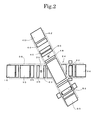
- Fig. 2 is a top view of the polarization plate manufacturing apparatus.
- a strip-shaped film 12 composed of a polarizer 12b and a release film 12a having a sticky agent applied thereto and laminated the polarizer 12b is unwound from an unwinder 10 through nip rolls 14.
- the release film 12a is removed from the film 12 by a rewinding roll 16 along the nip rolls 14, and the polarizer 12b to which the sticky agent is applied is supplied to a laminate /punch device 24 constituting a laminate /punch means through free rolls 20 and 22, thereby a polarizer transport means for transporting the polarizer 12b is arranged.
- a light source 26 composed of an incandescent lamp, a polarization device 28, and a photodetector 30 composed of a photodiode are disposed between the free rolls 20 and 22 to detect and control the angle of the polarizer 12b. More specifically, the absorption axis of the polarization device 28 is disposed in parallel with the roll axes of the unwinder 10, the nip rolls 14, and the free rolls 20 and 22, the angle of the polarizer 12b is controlled by an axially-movable rubber grip roll 32 so that the intensity of light detected by the photodetector 30 is minimized, and then the polarizer 12b is wound by a rewinder 34. These rolls and devices are mounted on and supported by a frame 36.
- two types of strip-shaped retarder 42a, 42b are rewound from an unwinder 40 through nip rolls 44.
- the retarder 42a, 42b are supplied to a position on the polarizer 12b, to which the sticky agent is applied, above the laminate -punch unit 24 at a predetermined gap through free rolls 46 and 48, thereby a retarder transport means for transporting the retarder 42a, 42b is arranged.
- a light source 50 composed of an incandescent lamp, a polarization device 52, a polarizer 54 disposed such that the absorption axis thereof is orthogonal to the polarization device 52, and a photodetector 56 composed of a photodiode are disposed between the free rolls 46 and 48 so that the angle of a retarder 42 is detected and controlled.
- the absorption axis of the polarization device 52 is disposed in parallel with the roll axes of the unwinder 40, the nip rolls 44, and the free rolls 46 and 48, the angles of the retarder 42a, 42b are controlled by a pair of axially-movable nip rolls 58 so that the intensity of light detected by the photodetector 56 is minimized, and the retarder 42 is wound by a rewinder 60.
- These rolls and the devices are mounted on and supported by a frame 62.
- the direction in which the retarder 42a, 42b are transported and the direction in which the polarizer 12b is transported can be set to have an arbitrary angle by changing the angle between the frames 36 and 62 according to an object of an optical film to be manufactured. After a target angle is set as described above, the angle can be controlled with a high accuracy by optically detecting the actual angle between the films as described above and minutely adjusting it.
- Both the films are laminated by the laminate /punch unit 24 and only the retarder 42a, 42b are cut off by being punched out.
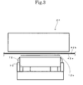
- Fig. 3 is an enlarged view of the laminate /punch unit 24 as well as a sectional view observed from a direction from which the polarizer 12b is transported.
- Fig. 4 is an enlarged view of the laminate /punch unit 24 and as well as a sectional view observed from a direction from which the retarder 42a, 42b are transported likewise.
- the polarizer 12b When a pressure plate 70 moves upward, the polarizer 12b is laminated the retarder 42a, 42b by predetermined pressure. Subsequently, a cutting blade 72 moves upward and cuts off only the retarder 42a, 42b to the width of the polarizer 12b. Next, the cutting blade 72 moves downward and returns to an initial position, and a cutting blade 78 moves downward by the thickness of the retarder 42a, 42b and cuts off only the retarder 42. At the time, the retarder 42a, 42b are punched out remaining a continuous ear portion so that the angle thereof can be controlled by the nip rolls 58. In the boding/punching operation, transportation of the polarizer 12b and the retarder 42a, 42b is temporarily stopped.
- a product which is composed of the polarizer 12b and the retarder 42a, 42b laminated the polarizer 12b, is rewound by the rewinder 34 in the roll state.
- the remaining ear portion from which the retarder 42a, 24b are cut off is rewound by the rewinder 60.
- the roll-state laminated product can be obtained as described above.
- Fig. 5 is a view showing an embodiment in which two types of strip-shaped retarder are laminated and laminated onto a strip-shaped polarizer.
- the retarder 42a, 42b are laminated the strip-shaped polarizer 12b such that the difference of the angle between drawing directions is within the range of 40° to 80°.
- the two types of the retarder 42a, 42b may have the same drawing direction or a different drawing direction, and they are transported in a laminated state.
- Fig. 6 shows a product composed of the polarizer onto which the retarder is laminated as described above, wherein a part (a) shows plan view and (b) shows a side elevational view.
- the punched-out retarder 42a, 42b are laminated the continuous polarizer 12b.
- the product composed of the polarizer onto which the retarder is laminated is not formed in an extremely slender parallelogram shape A as the laminated shape of the product. Since the parallelogram shape A as the laminated shape is an approximately regular parallelogram shape, a good handling property can be obtained and improvement of a yield ratio can be expected. Further, the size of the laminate /punch device 24 can be reduced because the parallelogram shape A is not made to an extremely slender shape, thereby an increase of length of the apparatus can be prevented because the installation area of the apparatus can be reduced.
- the polarization plate of the product in which the angle of the two the retarder 42a, 42b in the drawing direction thereof is 75° ⁇ 10° to the polarizer 12b and the retarder 42a, 42b are laminated the polarizer 12b, can be obtained.
- Fig. 7 is a view showing another embodiment of at least two types of strip-shaped retarder laminated and laminated onto a strip-shaped polarizer.
- the two types of the retarder 42a, 42b are laminated the strip-shaped polarizer 12b while being individually transported from different directions.
- the two types of the retarder 42a, 42b in the different drawing directions are laminated such that the difference of the angle between the drawing directions is within the range of 40° to 80°. It is possible to obtain a product of a polarization plate in which the angle of the retarder 42a on one hand in the drawing direction thereof to the polarizer 12b is 15° ⁇ 10°, the angle of the retarder 42b on the other hand in the drawing direction thereof to the polarizer 12b is 75° ⁇ 10°, and the retarder 42a, 42b are laminated the polarizer 12b.
- the fundamental structure of the polarizer used in the embodiment is as shown in Fig. 8.
- the strip-shaped polarizer 12b has such a structure that a polarizer film 12b1, which is, for example, a polarization layer and composed of PVA (polyvinyl alcohol) and the like, is sandwiched between two TAC (triacetyl cellulose) films 12b11, 12b12 as cellulose films.
- a sticky layer 12b13 is formed on the outside surface of the TAC film 12b13 on one hand
- the release film 12a is laminated the sticky layer 12b13.
- a protection film 12c is laminated the outside surface of the TAC film 12b12 on the other hand.
- the polarizer film 12b is colored with, for example, iodine, a dichroic dye, and the like to shut off light other than the light vibrating in a given direction.
- the fundamental structure of the strip-shaped retarder used in the embodiment is as shown in Fig. 9.
- the strip-shaped retarder 42a, 42b are retarder containing, for example, polycarbonate, polyethersulfone, and the like as a phase difference layer 42c1.
- Each of the retarder 42a, 42b has a protection film 42c2 laminated an outside surface thereof as well as a sticky layer 42c3 disposed on the other outside surface thereof so as to be laminated a liquid crystal display device, and a release film 42c4 is laminated the sticky layer 42c3.
- the fundamental structure of the product of the polarization plate in which the retarder 42a, 42b are laminated the polarizer 12b is as shown in Fig. 10.
- the release film 12a is removed from the polarizer 12b, and protection films 20b are removed from the retarder 42a, 42b, respectively, and the polarizer 12b is laminated the retarder 42a through the sticky layer 42c3. Further, the retarder 42b is laminated the retarder 42a.
- the types of the retarder to be laminate are not limited as long as a polarization plate, in which at least two types of retarder are laminated the polarizer 12b, is manufactured. Further, in the structure, since the two films of at least the two types of the retarder including at least the polarizer are laminated such that the difference of the angle between the drawing directions of the two films is within the range of 40° to 80°, laminating is carried out so that the difference of the angle between the polarizer and the drawing direction of any of the retarder or the difference of the angle between the drawing directions of the retarder is within the range of 40° to 80°.
- the two films of at least the two types of the retarder including at least the polarizer are laminated such that the difference of the angle between the drawing directions of the two films is within the range of 40° to 80°, they are not laminated in, for example, an extremely slender parallelogram shape. Accordingly, a good handling property can be obtained and improvement of a yield ratio can be expected as well since the size of the apparatus can be reduced, an increase in length of the apparatus can be prevented by reducing the installation area thereof.
Landscapes
- Engineering & Computer Science (AREA)
- Health & Medical Sciences (AREA)
- Manufacturing & Machinery (AREA)
- Ophthalmology & Optometry (AREA)
- Mechanical Engineering (AREA)
- Polarising Elements (AREA)
- Laminated Bodies (AREA)
Applications Claiming Priority (1)
| Application Number | Priority Date | Filing Date | Title |
|---|---|---|---|
| PCT/JP2005/005485 WO2006103715A1 (fr) | 2005-03-25 | 2005-03-25 | Procédé de fabrication de plaques de polarisation et équipement de fabrication de plaques de polarisation |
Publications (1)
| Publication Number | Publication Date |
|---|---|
| EP1868016A1 true EP1868016A1 (fr) | 2007-12-19 |
Family
ID=37052988
Family Applications (1)
| Application Number | Title | Priority Date | Filing Date |
|---|---|---|---|
| EP05721462A Withdrawn EP1868016A1 (fr) | 2005-03-25 | 2005-03-25 | Procédé de fabrication de plaques de polarisation et équipement de fabrication de plaques de polarisation |
Country Status (4)
| Country | Link |
|---|---|
| US (1) | US7955466B2 (fr) |
| EP (1) | EP1868016A1 (fr) |
| JP (1) | JPWO2006103715A1 (fr) |
| WO (1) | WO2006103715A1 (fr) |
Cited By (4)
| Publication number | Priority date | Publication date | Assignee | Title |
|---|---|---|---|---|
| WO2012107157A1 (fr) * | 2011-02-10 | 2012-08-16 | Heraeus Materials Technology Gmbh & Co. Kg | Procédé de stratification par matriçage d'un premier film sur un film continu |
| US20130202871A1 (en) * | 2012-02-03 | 2013-08-08 | E I Du Pont De Nemours And Company | Polyimide sheet and manufacturing method thereof |
| EP3089335A1 (fr) * | 2015-04-30 | 2016-11-02 | STAMPTEC-Holding GmbH | Dispositif et procédé de liaison de parties de tôles à un paquet de tôles |
| CN110140285A (zh) * | 2016-10-27 | 2019-08-16 | 奥钢联汽车零部件代廷根两合公司 | 用于将板材件连接成板材组的设备和方法 |
Families Citing this family (5)
| Publication number | Priority date | Publication date | Assignee | Title |
|---|---|---|---|---|
| WO2012140503A2 (fr) | 2011-04-15 | 2012-10-18 | Polaroid Eyewear A Division Of Stylemark Uk, Ltd. | Lentilles incurvées et procédés associés |
| EP2697672B1 (fr) | 2011-04-15 | 2018-07-04 | Safilo S.P.A. | Procédé de production de lentilles incurvées |
| WO2012140502A2 (fr) | 2011-04-15 | 2012-10-18 | Polaroid Eyewear A Division Of Stylemark Uk, Ltd. | Lentilles incurvées et procédés associés |
| CN104407739A (zh) * | 2014-11-27 | 2015-03-11 | 京东方科技集团股份有限公司 | 一种膜材的贴附方法 |
| EP4168248A4 (fr) * | 2020-06-21 | 2024-07-24 | Meta Platforms Technologies, LLC | Équipement et procédés de fabrication de précision d'empilements de retardateurs stratifiés par solvant |
Family Cites Families (6)
| Publication number | Priority date | Publication date | Assignee | Title |
|---|---|---|---|---|
| JPH11231129A (ja) * | 1997-11-17 | 1999-08-27 | Sumitomo Chem Co Ltd | 光学フィルム積層中間体およびその製造方法ならびに光学フィルム積層チップの製造方法 |
| JP2004020701A (ja) * | 2002-06-13 | 2004-01-22 | Nippon Zeon Co Ltd | 光学積層体 |
| JP4397644B2 (ja) * | 2002-08-30 | 2010-01-13 | 富士フイルム株式会社 | 位相差板及びその製造方法、それを用いた円偏光板及び1/2波長板、並びに、反射型液晶表示装置 |
| US20040041968A1 (en) * | 2002-08-30 | 2004-03-04 | Fuji Photo Film Co., Ltd. | Retardation plate and its manufacturing method, circularly polarizing plate and 1/2 wave plate using same, and a reflective liquid crystal display |
| JP4225042B2 (ja) * | 2002-12-02 | 2009-02-18 | 住友化学株式会社 | 半透過半反射性偏光フィルム並びにそれを用いた偏光光源装置及び液晶表示装置 |
| JP4518916B2 (ja) * | 2004-11-08 | 2010-08-04 | 東レ株式会社 | 積層体の製造方法 |
-
2005
- 2005-03-25 JP JP2007510246A patent/JPWO2006103715A1/ja active Pending
- 2005-03-25 US US11/663,200 patent/US7955466B2/en not_active Expired - Fee Related
- 2005-03-25 WO PCT/JP2005/005485 patent/WO2006103715A1/fr not_active Ceased
- 2005-03-25 EP EP05721462A patent/EP1868016A1/fr not_active Withdrawn
Non-Patent Citations (1)
| Title |
|---|
| See references of WO2006103715A1 * |
Cited By (7)
| Publication number | Priority date | Publication date | Assignee | Title |
|---|---|---|---|---|
| WO2012107157A1 (fr) * | 2011-02-10 | 2012-08-16 | Heraeus Materials Technology Gmbh & Co. Kg | Procédé de stratification par matriçage d'un premier film sur un film continu |
| JP2014509275A (ja) * | 2011-02-10 | 2014-04-17 | ヘレーウス マテリアルズ テクノロジー ゲゼルシャフト ミット ベシュレンクテル ハフツング ウント コンパニー コマンディートゲゼルシャフト | フィルムウェブに第1のフィルムを打抜きラミネートする方法 |
| US20130202871A1 (en) * | 2012-02-03 | 2013-08-08 | E I Du Pont De Nemours And Company | Polyimide sheet and manufacturing method thereof |
| EP3089335A1 (fr) * | 2015-04-30 | 2016-11-02 | STAMPTEC-Holding GmbH | Dispositif et procédé de liaison de parties de tôles à un paquet de tôles |
| EP3506468A1 (fr) * | 2015-04-30 | 2019-07-03 | voestalpine Automotive Components Dettingen GmbH & Co. KG | Dispositif et procédé d'assemblage des parties de tôles pour former un paquet de tôles |
| CN110140285A (zh) * | 2016-10-27 | 2019-08-16 | 奥钢联汽车零部件代廷根两合公司 | 用于将板材件连接成板材组的设备和方法 |
| CN110140285B (zh) * | 2016-10-27 | 2021-07-23 | 奥钢联汽车零部件代廷根两合公司 | 用于将板材件连接成板材组的设备和方法 |
Also Published As
| Publication number | Publication date |
|---|---|
| US20090205773A1 (en) | 2009-08-20 |
| WO2006103715A1 (fr) | 2006-10-05 |
| JPWO2006103715A1 (ja) | 2008-09-04 |
| US7955466B2 (en) | 2011-06-07 |
Similar Documents
| Publication | Publication Date | Title |
|---|---|---|
| US8088463B2 (en) | Set of material rolls and method for production of material roll | |
| CN101910925B (zh) | 用于连续制造液晶显示元件的方法与装置 | |
| KR102027010B1 (ko) | 광학 표시 패널의 제조 방법 및 광학 표시 패널의 제조 시스템 | |
| US7022204B2 (en) | Method and apparatus for bonding polarizing plate | |
| KR102369758B1 (ko) | 결함 검사 시스템 | |
| EP2315071B1 (fr) | Procédé et système pour fabriquer de manière continue un élément d'affichage à cristaux liquides | |
| TWI524985B (zh) | A continuous manufacturing method of an optical display panel and a continuous manufacturing system for an optical display panel | |
| JP6529250B2 (ja) | 光学表示パネルの製造方法および光学表示パネルの製造システム | |
| KR20130120528A (ko) | 광학 필름 롤 세트 및 광학 필름 롤 세트의 제조 방법 | |
| TWI577534B (zh) | A continuous manufacturing method of an optical display panel and a continuous manufacturing system for an optical display panel | |
| EP1868016A1 (fr) | Procédé de fabrication de plaques de polarisation et équipement de fabrication de plaques de polarisation | |
| WO2011162271A1 (fr) | Procédé et système de production d'un écran à cristaux liquides | |
| KR20130114740A (ko) | 광학 표시 패널의 연속 제조 방법 및 광학 표시 패널의 연속 제조 시스템 | |
| JP6069842B2 (ja) | 光学フィルムチップの切り出し装置、光学フィルムチップの製造システム及び光学フィルムチップの切り出し方法 | |
| KR20140019425A (ko) | 나이프 엣지 및 이것을 포함하는 액정 표시 장치의 제조 시스템 | |
| US7757737B2 (en) | Film pasting device | |
| KR20150066773A (ko) | 편광판 제조방법 및 이에 적용되는 편광판 제조 시스템 | |
| KR102231024B1 (ko) | 절단면을 갖는 긴 광학 필름을 반송하는 반송 장치, 및 광학 표시 패널의 연속 제조 시스템 | |
| KR102350662B1 (ko) | 광학필름 재단장치 | |
| CN113109952A (zh) | 用于制造光学显示元件的系统和方法 | |
| WO2019135299A1 (fr) | Dispositif de transport permettant de transporter un film optique allongé ayant une découpe, et système de fabrication continue de panneaux d'affichage optique | |
| KR20110093263A (ko) | 편광판의 커팅 장치 및 방법 | |
| US20210226176A1 (en) | System and method for manufacturing optical display element | |
| KR20110083882A (ko) | 레이저 절단 장치 및 방법 |
Legal Events
| Date | Code | Title | Description |
|---|---|---|---|
| PUAI | Public reference made under article 153(3) epc to a published international application that has entered the european phase |
Free format text: ORIGINAL CODE: 0009012 |
|
| 17P | Request for examination filed |
Effective date: 20071023 |
|
| AK | Designated contracting states |
Kind code of ref document: A1 Designated state(s): AT BE BG CH CY CZ DE DK EE ES FI FR GB GR HU IE IS IT LI LT LU MC NL PL PT RO SE SI SK TR |
|
| RIN1 | Information on inventor provided before grant (corrected) |
Inventor name: NOZAKI, ATSUO |
|
| DAX | Request for extension of the european patent (deleted) | ||
| STAA | Information on the status of an ep patent application or granted ep patent |
Free format text: STATUS: THE APPLICATION IS DEEMED TO BE WITHDRAWN |
|
| 18D | Application deemed to be withdrawn |
Effective date: 20101001 |