EP1868109A1 - Signalisation d'évènement entre des modules périphériques et une unité de traitement - Google Patents
Signalisation d'évènement entre des modules périphériques et une unité de traitement Download PDFInfo
- Publication number
- EP1868109A1 EP1868109A1 EP06012059A EP06012059A EP1868109A1 EP 1868109 A1 EP1868109 A1 EP 1868109A1 EP 06012059 A EP06012059 A EP 06012059A EP 06012059 A EP06012059 A EP 06012059A EP 1868109 A1 EP1868109 A1 EP 1868109A1
- Authority
- EP
- European Patent Office
- Prior art keywords
- processing unit
- peripheral
- event
- module
- telegram
- Prior art date
- Legal status (The legal status is an assumption and is not a legal conclusion. Google has not performed a legal analysis and makes no representation as to the accuracy of the status listed.)
- Ceased
Links
Images


Classifications
-
- G—PHYSICS
- G06—COMPUTING OR CALCULATING; COUNTING
- G06F—ELECTRIC DIGITAL DATA PROCESSING
- G06F13/00—Interconnection of, or transfer of information or other signals between, memories, input/output devices or central processing units
- G06F13/38—Information transfer, e.g. on bus
- G06F13/42—Bus transfer protocol, e.g. handshake; Synchronisation
- G06F13/4247—Bus transfer protocol, e.g. handshake; Synchronisation on a daisy chain bus
- G06F13/426—Bus transfer protocol, e.g. handshake; Synchronisation on a daisy chain bus using an embedded synchronisation, e.g. Firewire bus, Fibre Channel bus, SSA bus
Definitions
- the invention relates to a method for event signaling between at least one peripheral module and a processing unit by means of a system bus, wherein the system bus is operated by a system bus master which can read or send data from the peripheral modules, the data being composed of individual characters, which are transcribed for transmission in a physical layer at a transmitter by a coder in a larger character space and converted back at a receiver by a decoder, wherein for the data transmission, a telegram method according to the request / response paradigm is used in which certain characters from the larger character space for characterizing the start and end of a telegram and a standard idle character in telegram pauses used to synchronize a connection between the sender and the receiver.
- the invention further relates to a bus protocol based on said method and to a peripheral module, a processing unit and an event signaling hub according to said method. Finally, the invention relates to a system of said components in which said method finds application using said bus protocol.
- Such a method and / or a system with the named components using said bus protocol is used in all areas in which peripheral modules communicate with a processing unit via a system bus, as is the case in particular in automation technology.
- the main requirements are as follows:
- the system module master must access the I / O modules as quickly as possible and with less speed via direct access Latency can be accessed, the peripheral modules should be able to report as soon as possible pending alarms or pending communication requirements to the system bus master and the communication connection of the peripheral modules must be cost-effectively feasible.
- the system bus master is either the (central) processing unit (CPU), which processes the data of the peripheral modules, or an interface module, which decentrally establishes the coupling between the peripheral modules and the central processing unit via a fieldbus.
- the peripheral modules are the input and output modules that receive the data from the system bus master or from which the system bus master can read data.
- the I / O modules connect to the automation process. Furthermore, for example, when connecting the components to a backplane structure, it is possible to use a hub which behaves like an I / O module with regard to event signaling.
- the pending jobs are prioritized by a scheduler in the system bus interface of the system bus master and sent to the I / O modules via the system bus.
- the I / O modules may only send data to the bus if they have received a request from the CPU, ie the system bus master responds to a peripheral module by means of a request and expects a corresponding response. Due to process or diagnostic events, the I / O modules must also be able to send a message to the CPU which must be transported to the CPU as quickly as possible and processed there.
- peripheral modules typically up to 64
- the transport of the messages to the CPU must be controlled by a special mechanism since, in the worst case, all peripheral modules want to send a message to the CPU at the same time.
- Profibus also supports a polling procedure in which the master polls all slaves, ie the mentioned peripheral modules, and reads the data from the I / O modules or writes them to the I / O modules. Also in this case, the response or reporting time depends on the polling cycle of the CPU until a module can signal to the CPU that an alarm or communication request is present.
- the switched networks have prevailed at 100 Mbps.
- the throughput and the response time depend to a great extent on the available message memory in the individual switches and the arrangement (topology) of the switches and the nodes.
- Each participant may send at any time.
- the CPU in case of event signaling. This depends on the remaining telegram volume. If there is a collision because two parties are transmitting at the same time, this collision is resolved by the memory in the switch. The message that arrives later will be cached in the switch and sent after the first message has been completed.
- Ethernet offers baud rates of 10, 100, and 1000 Mbps and above.
- an additional hardware line is provided for the message path from the peripheral modules to the CPU.
- the system bus master had to read out the status from the I / O modules and determine which module would like to send a message to the CPU, whereupon the CPU could then actively read the message from the I / O module. This resulted in a high latency because the CPU did not immediately know which I / O module had which message.
- the CPU can not know which module would like to send a message to the CPU at what point in time, a solution is required in which a message can be transmitted from the peripheral modules to the processing unit independently of the message processing by the CPU. Furthermore, the system bus should be able to work with baud rates of several hundred Mbps.
- a telegram method according to the request / response paradigm is suitable in which the data, which are composed of individual characters, for transmission in a physical layer at a transmitter by a coder into a larger character space be recoded at a receiver by a decoder and certain characters from the larger character space to mark the start and end of a telegram and a standard idle character in telegram pauses used to synchronize a connection between the sender and the receiver.
- an 8B / 10B encoding is known, which is also used in Gigabit Ethernet.
- the 10-bit characters are converted back to 8-bit characters by a decoder.
- the 10-bit characters have at least four level changes, whereby DC-freedom is ensured and clock information for synchronization of the transmission stations can be obtained from the data stream.
- a maximum of 256 characters are possible, which can be distributed by the conversion to the 10 bits to 1024 characters.
- the encoding rules used state that the 256 characters are split into two disjoint character spaces in 10-bit character space, occupying 512 10-bit characters. This leaves 512 characters that are not used as data characters. From this additional set of characters, certain characters stand out due to their "safety margin" to other characters. These characters are used to mark the start and end of a telegram and to keep the connection between the send port and the receive port synchronized in the telegram pauses.
- This 8B / 10B encoding is actually a combined 5B / 6B and 3B / 4B encoding.
- the DC-free and integrated synchronization however, you buy with a 25% higher demand for bandwidth.
- With the 64B / 66B encoding exists a further development of this method, in which only about 3% bandwidth is needed more.
- the invention has for its object to provide a method by which the peripheral modules, regardless of the telegram traffic, which is initiated by the processing unit, can signal a present message to the processing unit.
- Another object of the present invention is to provide a bus protocol which enables such communication between the peripheral modules and the processing unit on the system bus.
- the invention is further based on the object of specifying a peripheral module, a processing unit and a hub and an existing system consisting of these components, wherein the components means for signaling a present at the peripheral modules message to the processing unit regardless of the telegram traffic, initiated by the processing unit is, have.
- This object is achieved in a method of the type mentioned in that an I / O module that wants to signal the processing unit an event sends to the processing unit in a telegram pause instead of the standard idle character a signaling sequence consisting of an alarm-idle character and an alarm identifier containing information about the event in question as well as the module address of the peripheral module on which the event is present, the information about the Event also be recoded into the larger drawing space.
- the object is further achieved by a bus protocol, a peripheral module, a processing unit, a hub and a system of the type mentioned above with the features mentioned in claims 9, 12, 18, 23 and 26, respectively.
- the processing unit receives the information via the signaling sequence that there is a message from a specific peripheral module which is to be fetched by the processing unit.
- the relevant peripheral module in the telegram pauses instead of the standard idle character sends an alarm-idle character, followed by further information in the alarm identifier
- the telegram traffic (request / response telegrams) becomes functional and time-delayed by the signaling sequence practically unaffected. This relieves the system bus master of coordination tasks.
- the processing unit can determine the most varied information based on the signaling sequences. For example, the processing unit immediately recognizes from which peripheral module which message is present. Furthermore, this mechanism eliminates one or more additional hardware lines for signaling messages from the peripheral modules to the processing unit.
- the signaling sequence is interrupted at any point in the character string when a request or a response message is sent. This ensures that the normal data transfer is not affected.
- this mechanism for the first signaling sequence indicates a process alarm, a calculable, deterministic response time can be specified. This consists of the pure transit time of the signaling sequence and a possible latency, if a maximum long telegram before the signaling sequence must be transmitted together.
- the processing unit is used as a system bus master, which eliminates the need for an additional interface module.
- an interface module is alternatively used as a system bus master, which establishes a coupling between the peripheral modules and the processing unit via a field bus, whereby a discharge of the processing unit is achieved.
- the signaling sequence is sent by the peripheral module until the processing unit signals to the peripheral module through appropriate telegrams that the signaling sequence has arrived at the processing unit, whereby a maximum of security is achieved.
- the processing unit and the peripheral modules are interconnected in a daisy-chain or backplane configuration.
- daisy-chain or backplane configuration are the usual basic designs of a system bus, which can be easily realized with the invention.
- the method is provided for event signaling in the field of automation technology, wherein the processing unit is designed as a programmable logic controller.
- the processing unit is designed as a programmable logic controller.
- the peripheral module has a sample stage for storing a message to be sent Signaling sequence on. Since only one signaling sequence can be sent simultaneously, it may be necessary to determine the first event to be reported from possibly several present events in accordance with rules to be defined, with the resulting signaling sequence being recorded in the sample stage.
- the peripheral module has at least one further transmitter and at least one further receiver for connecting further peripheral modules.
- This allows a daisy-chain connection in which the processing unit and the peripheral modules are connected in series.
- the processing unit does not necessarily have to be at one end of the row, but it can also be present in the middle of the row.
- the peripheral module has a hold stage for storing signaling sequences of further peripheral modules.
- the signaling sequence is then fed to the sample stage.
- the peripheral module has a priority level for evaluating both its own signaling sequences and those of other peripheral modules and forwarding the signaling sequence with the highest priority.
- the thus prioritized signaling sequences have in their alarm identifier a field for the assigned priority, so that the importance of the corresponding event can be read directly from the signaling sequence.
- the processing unit has at least one further transmitter and at least one further receiver for connecting further peripheral modules.
- the processing unit can be interconnected in a daisy-chain design between two peripheral modules or in a backplane structure without additional hub.
- the processing unit has a hold stage for each receiver to store signaling sequences of the peripheral modules. If signaling sequences are present at the same time, then the event to be processed first can be determined according to rules to be defined.
- the processing unit has a priority level for evaluating the signaling sequences from the peripheral modules and processing the highest priority signaling sequence.
- the hub also has a sample and / or hold stage for storing the signaling sequences to be transmitted and / or received.
- FIG. 1 shows a flow diagram of a communication between a processing unit 1 and a peripheral module 2.
- the transmission between these two modules 1, 2 takes place via point-to-point connections between the communication ports 3, 4.
- the transmission between a transmitter 3 and a receiver 4 may be e.g. based on LVDS (Low Voltage Differential Signaling). This is a differential interface standard for high-speed data transmission (ANSI / TIA / EIA-644-1995, IEEE 1596.3-1996).
- LVDS Low Voltage Differential Signaling
- the individual characters which make up the data to be transmitted, are recoded into a larger character space.
- This can for example be done with an 8B / 10B coding, ie an 8-bit character is converted at the transmitter 3 by a coder into a 10-bit character and at the receiver 4 by a decoder back into an 8-bit character.
- an unused character stock remains, from which certain characters protrude due to their "safety margin".
- comma characters which, even with any combination of these characters and all other characters, do not create commas across character boundaries. These characters are therefore ideal for finding the character boundaries within the data stream.
- the standard idle character 5 is transmitted in the telegram pauses between ports 3, 4 of two modules. In order to the transmission link is also synchronized in the telegram pauses.
- the processing unit 1 sends a request telegram 6 to the peripheral module 2 (upper image in the figure) and receives a response telegram 7 from the peripheral module 2 (second image from above). If there is an event present in the peripheral module 2 that wishes to report this to the processing unit 1, it sends instead of the standard idle character 5 a signaling sequence 8 which is repeated until the processing unit 1 signals the peripheral module 2 by corresponding telegrams in that the message has arrived at the processing unit 1. Meanwhile, the processing unit 1 can also send another request 6 to the peripheral module 2 (second image from below). In this case, the peripheral module 2 can immediately return the response 7 to the request 6 of the processing unit 1, since the signaling sequence 8 can be interrupted at each character boundary.
- This consists of an alarm-idle character 9 and an alarm identifier 10.
- the alarm-idle character 9 is another character from the group of comma characters
- the alarm identifier 10 further information about the message in question such as the module address of the relevant peripheral module 2, a priority of the event message 8 and which message / information is present on the peripheral module 2 supplies.
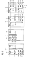
- FIG. 3 shows an embodiment of the system according to the invention in a daisy-chain design.
- the system has a peripheral module 2 to the left of the processing unit 1 and further peripheral modules 2 to the right of the processing unit 1.
- each peripheral module 2 in this example, three different alarm messages 14-16 may be present. These are fed to a priority stage 13, which evaluates the signaling sequences 8 and forwards the signaling sequence 8 with the highest priority. If two signaling sequences 8 with the same priority exist, then a priority scheme defined on the system bus applies, which determines in this case which signaling sequence 8 is forwarded.
- the neighboring modules 2 and the processing unit 1 have a hold stage 12, which receives the incoming signaling sequences 8.
- the processing unit 1 has two hold stages 12, in which the incoming signaling sequences 8 are stored and supplied from here to the priority stage 13, which decides which of the possible alarm messages 14-16 is processed first.
- the system in addition to the processing unit 1 on the left in the image and the peripheral modules 2 on the right, the system also has a hub 17, by means of which the connection between the peripheral modules 2 and the processing unit 1 is established. Structure and operation of the peripheral modules 2 is described as in the outer peripheral modules 2 in the daisy-chain structure in Figure 3.
- the signaling sequences 8 sent by the peripheral modules 2 become stored in the hub 17 in each case a hold stage 12, ie, the hub 17 has a hold stage 12 for each peripheral module 2 and for each module slot on the backplane.
- These signaling sequences 8 are now forwarded with possible own alarm messages 14-16 of the hub 17 to the priority level 13 of the hub 17 for prioritization.
- the resulting signaling sequence 8, which is sent to the processing unit 1, is stored again in a sample stage 11 of the hub.
- only one signaling sequence 8 arrives in the processing unit 1, so that the processing unit 1, unlike the one described in the daisy-chain structure, has only one hold stage 12 and thus also does not require a priority stage 13.
- FIG. 5 shows an embodiment of the system according to the invention in a construction with two hubs 17.
- the structure essentially corresponds to that of FIG. 4, with an additional hub 17 being located to the left of the processing unit 1.
- the other peripheral modules 2 which can be connected to this additional hub 17.
- the processing unit 1 in the structure in this FIG. 5 requires two hold stages 12, in which the signaling sequences 8 sent by the two hubs 17 are stored. It follows that the processing unit 1 in the structure with two hubs 17 also requires a priority stage 13 for prioritizing the incoming signaling sequences 8.
- the processing unit 1 in the structure with two hubs 17 also requires a priority stage 13 for prioritizing the incoming signaling sequences 8.
- the invention relates to a method, a bus protocol, an I / O module, a processing unit, a hub and a system of said components for event signaling between at least one peripheral module and a processing unit by means of a system bus.
- the data to be transmitted is encoded into a larger character space, from which a standard idle character in Telegram pauses are used to synchronize a connection between transmitter and receiver.
- the invention has for its object to be able to signal a present at the peripheral modules message regardless of telegram traffic, which is initiated by the processing unit to the processing unit.
- an I / O module which wishes to signal an event to the processing unit sends to the processing unit, in a message pause, instead of the standard idle character, a signaling sequence consisting of an alarm-idle character and an alarm identifier. contains the information about the event in question as well as the module address of the peripheral module on which the event is present, the information about the event also being recoded into the larger character space.
Landscapes
- Engineering & Computer Science (AREA)
- Theoretical Computer Science (AREA)
- Physics & Mathematics (AREA)
- General Engineering & Computer Science (AREA)
- General Physics & Mathematics (AREA)
- Bus Control (AREA)
Priority Applications (2)
| Application Number | Priority Date | Filing Date | Title |
|---|---|---|---|
| EP06012059A EP1868109A1 (fr) | 2006-06-12 | 2006-06-12 | Signalisation d'évènement entre des modules périphériques et une unité de traitement |
| US11/811,941 US8060672B2 (en) | 2006-06-12 | 2007-06-12 | Event signaling between peripheral modules and a processing unit |
Applications Claiming Priority (1)
| Application Number | Priority Date | Filing Date | Title |
|---|---|---|---|
| EP06012059A EP1868109A1 (fr) | 2006-06-12 | 2006-06-12 | Signalisation d'évènement entre des modules périphériques et une unité de traitement |
Publications (1)
| Publication Number | Publication Date |
|---|---|
| EP1868109A1 true EP1868109A1 (fr) | 2007-12-19 |
Family
ID=37097346
Family Applications (1)
| Application Number | Title | Priority Date | Filing Date |
|---|---|---|---|
| EP06012059A Ceased EP1868109A1 (fr) | 2006-06-12 | 2006-06-12 | Signalisation d'évènement entre des modules périphériques et une unité de traitement |
Country Status (2)
| Country | Link |
|---|---|
| US (1) | US8060672B2 (fr) |
| EP (1) | EP1868109A1 (fr) |
Cited By (2)
| Publication number | Priority date | Publication date | Assignee | Title |
|---|---|---|---|---|
| EP2466805A1 (fr) * | 2010-12-16 | 2012-06-20 | Pepperl & Fuchs GmbH | Procédé de transmission de données entre deux participants, convertisseur d'émission et de réception de données et voie de transmission de données |
| EP2523119A1 (fr) * | 2011-05-13 | 2012-11-14 | Siemens Aktiengesellschaft | Procédé de transmission de données en série |
Families Citing this family (65)
| Publication number | Priority date | Publication date | Assignee | Title |
|---|---|---|---|---|
| EP2028797B1 (fr) * | 2007-08-23 | 2010-02-24 | Siemens Aktiengesellschaft | Procédé de transmission de données |
| US9377768B2 (en) * | 2008-10-27 | 2016-06-28 | Lennox Industries Inc. | Memory recovery scheme and data structure in a heating, ventilation and air conditioning network |
| US8437878B2 (en) * | 2008-10-27 | 2013-05-07 | Lennox Industries Inc. | Alarm and diagnostics system and method for a distributed architecture heating, ventilation and air conditioning network |
| US8661165B2 (en) * | 2008-10-27 | 2014-02-25 | Lennox Industries, Inc. | Device abstraction system and method for a distributed architecture heating, ventilation and air conditioning system |
| US8798796B2 (en) | 2008-10-27 | 2014-08-05 | Lennox Industries Inc. | General control techniques in a heating, ventilation and air conditioning network |
| US9152155B2 (en) * | 2008-10-27 | 2015-10-06 | Lennox Industries Inc. | Device abstraction system and method for a distributed-architecture heating, ventilation and air conditioning system |
| US20100106326A1 (en) * | 2008-10-27 | 2010-04-29 | Lennox Industries Inc. | Communication protocol system and method for a distributed-architecture heating, ventilation and air conditioning network |
| US20100106810A1 (en) * | 2008-10-27 | 2010-04-29 | Lennox Industries Inc. | Communication protocol system and method for a distributed-architecture heating, ventilation and air conditioning network |
| US8255086B2 (en) * | 2008-10-27 | 2012-08-28 | Lennox Industries Inc. | System recovery in a heating, ventilation and air conditioning network |
| US8892797B2 (en) * | 2008-10-27 | 2014-11-18 | Lennox Industries Inc. | Communication protocol system and method for a distributed-architecture heating, ventilation and air conditioning network |
| US8437877B2 (en) * | 2008-10-27 | 2013-05-07 | Lennox Industries Inc. | System recovery in a heating, ventilation and air conditioning network |
| US20100106957A1 (en) * | 2008-10-27 | 2010-04-29 | Lennox Industries Inc. | Programming and configuration in a heating, ventilation and air conditioning network |
| US9651925B2 (en) | 2008-10-27 | 2017-05-16 | Lennox Industries Inc. | System and method for zoning a distributed-architecture heating, ventilation and air conditioning network |
| US20100107072A1 (en) * | 2008-10-27 | 2010-04-29 | Lennox Industries Inc. | System and method of use for a user interface dashboard of a heating, ventilation and air conditioning network |
| US8295981B2 (en) * | 2008-10-27 | 2012-10-23 | Lennox Industries Inc. | Device commissioning in a heating, ventilation and air conditioning network |
| US8352080B2 (en) * | 2008-10-27 | 2013-01-08 | Lennox Industries Inc. | Communication protocol system and method for a distributed-architecture heating, ventilation and air conditioning network |
| US9325517B2 (en) * | 2008-10-27 | 2016-04-26 | Lennox Industries Inc. | Device abstraction system and method for a distributed-architecture heating, ventilation and air conditioning system |
| US9268345B2 (en) * | 2008-10-27 | 2016-02-23 | Lennox Industries Inc. | System and method of use for a user interface dashboard of a heating, ventilation and air conditioning network |
| US9432208B2 (en) | 2008-10-27 | 2016-08-30 | Lennox Industries Inc. | Device abstraction system and method for a distributed architecture heating, ventilation and air conditioning system |
| US8452456B2 (en) * | 2008-10-27 | 2013-05-28 | Lennox Industries Inc. | System and method of use for a user interface dashboard of a heating, ventilation and air conditioning network |
| US8788100B2 (en) | 2008-10-27 | 2014-07-22 | Lennox Industries Inc. | System and method for zoning a distributed-architecture heating, ventilation and air conditioning network |
| US8442693B2 (en) | 2008-10-27 | 2013-05-14 | Lennox Industries, Inc. | System and method of use for a user interface dashboard of a heating, ventilation and air conditioning network |
| US8239066B2 (en) * | 2008-10-27 | 2012-08-07 | Lennox Industries Inc. | System and method of use for a user interface dashboard of a heating, ventilation and air conditioning network |
| US9261888B2 (en) | 2008-10-27 | 2016-02-16 | Lennox Industries Inc. | System and method of use for a user interface dashboard of a heating, ventilation and air conditioning network |
| US8463442B2 (en) * | 2008-10-27 | 2013-06-11 | Lennox Industries, Inc. | Alarm and diagnostics system and method for a distributed architecture heating, ventilation and air conditioning network |
| US9632490B2 (en) | 2008-10-27 | 2017-04-25 | Lennox Industries Inc. | System and method for zoning a distributed architecture heating, ventilation and air conditioning network |
| US8994539B2 (en) * | 2008-10-27 | 2015-03-31 | Lennox Industries, Inc. | Alarm and diagnostics system and method for a distributed-architecture heating, ventilation and air conditioning network |
| US8463443B2 (en) * | 2008-10-27 | 2013-06-11 | Lennox Industries, Inc. | Memory recovery scheme and data structure in a heating, ventilation and air conditioning network |
| US20100106312A1 (en) * | 2008-10-27 | 2010-04-29 | Lennox Industries Inc. | Alarm and diagnostics system and method for a distributed-architecture heating, ventilation and air conditioning network |
| US8600559B2 (en) * | 2008-10-27 | 2013-12-03 | Lennox Industries Inc. | Method of controlling equipment in a heating, ventilation and air conditioning network |
| US8615326B2 (en) * | 2008-10-27 | 2013-12-24 | Lennox Industries Inc. | System and method of use for a user interface dashboard of a heating, ventilation and air conditioning network |
| US8600558B2 (en) * | 2008-10-27 | 2013-12-03 | Lennox Industries Inc. | System recovery in a heating, ventilation and air conditioning network |
| US8452906B2 (en) | 2008-10-27 | 2013-05-28 | Lennox Industries, Inc. | Communication protocol system and method for a distributed-architecture heating, ventilation and air conditioning network |
| US8977794B2 (en) * | 2008-10-27 | 2015-03-10 | Lennox Industries, Inc. | Communication protocol system and method for a distributed-architecture heating, ventilation and air conditioning network |
| US8744629B2 (en) * | 2008-10-27 | 2014-06-03 | Lennox Industries Inc. | System and method of use for a user interface dashboard of a heating, ventilation and air conditioning network |
| US8560125B2 (en) * | 2008-10-27 | 2013-10-15 | Lennox Industries | Communication protocol system and method for a distributed-architecture heating, ventilation and air conditioning network |
| US8762666B2 (en) * | 2008-10-27 | 2014-06-24 | Lennox Industries, Inc. | Backup and restoration of operation control data in a heating, ventilation and air conditioning network |
| US8564400B2 (en) * | 2008-10-27 | 2013-10-22 | Lennox Industries, Inc. | Communication protocol system and method for a distributed-architecture heating, ventilation and air conditioning network |
| US8694164B2 (en) * | 2008-10-27 | 2014-04-08 | Lennox Industries, Inc. | Interactive user guidance interface for a heating, ventilation and air conditioning system |
| US8655491B2 (en) * | 2008-10-27 | 2014-02-18 | Lennox Industries Inc. | Alarm and diagnostics system and method for a distributed architecture heating, ventilation and air conditioning network |
| US8433446B2 (en) * | 2008-10-27 | 2013-04-30 | Lennox Industries, Inc. | Alarm and diagnostics system and method for a distributed-architecture heating, ventilation and air conditioning network |
| US8874815B2 (en) * | 2008-10-27 | 2014-10-28 | Lennox Industries, Inc. | Communication protocol system and method for a distributed architecture heating, ventilation and air conditioning network |
| US8855825B2 (en) | 2008-10-27 | 2014-10-07 | Lennox Industries Inc. | Device abstraction system and method for a distributed-architecture heating, ventilation and air conditioning system |
| US8774210B2 (en) | 2008-10-27 | 2014-07-08 | Lennox Industries, Inc. | Communication protocol system and method for a distributed-architecture heating, ventilation and air conditioning network |
| US8725298B2 (en) * | 2008-10-27 | 2014-05-13 | Lennox Industries, Inc. | Alarm and diagnostics system and method for a distributed architecture heating, ventilation and conditioning network |
| US8543243B2 (en) * | 2008-10-27 | 2013-09-24 | Lennox Industries, Inc. | System and method of use for a user interface dashboard of a heating, ventilation and air conditioning network |
| US8352081B2 (en) | 2008-10-27 | 2013-01-08 | Lennox Industries Inc. | Communication protocol system and method for a distributed-architecture heating, ventilation and air conditioning network |
| US9678486B2 (en) * | 2008-10-27 | 2017-06-13 | Lennox Industries Inc. | Device abstraction system and method for a distributed-architecture heating, ventilation and air conditioning system |
| US8548630B2 (en) | 2008-10-27 | 2013-10-01 | Lennox Industries, Inc. | Alarm and diagnostics system and method for a distributed-architecture heating, ventilation and air conditioning network |
| US8655490B2 (en) * | 2008-10-27 | 2014-02-18 | Lennox Industries, Inc. | System and method of use for a user interface dashboard of a heating, ventilation and air conditioning network |
| US8802981B2 (en) * | 2008-10-27 | 2014-08-12 | Lennox Industries Inc. | Flush wall mount thermostat and in-set mounting plate for a heating, ventilation and air conditioning system |
| USD648641S1 (en) | 2009-10-21 | 2011-11-15 | Lennox Industries Inc. | Thin cover plate for an electronic system controller |
| USD648642S1 (en) | 2009-10-21 | 2011-11-15 | Lennox Industries Inc. | Thin cover plate for an electronic system controller |
| US8260444B2 (en) | 2010-02-17 | 2012-09-04 | Lennox Industries Inc. | Auxiliary controller of a HVAC system |
| US8717181B2 (en) | 2010-07-29 | 2014-05-06 | Hill-Rom Services, Inc. | Bed exit alert silence with automatic re-enable |
| DE102011083476A1 (de) * | 2011-09-27 | 2013-03-28 | Robert Bosch Gmbh | Kommunikationsanordnung mit logischer Mehrkanal-Kommunikation über eine physikalische Übertragungsstrecke zur seriellen Interchip-Datenübertragung |
| US9542347B2 (en) | 2013-03-16 | 2017-01-10 | Intel Corporation | Host interface crossbar for sensor hub |
| US9430414B2 (en) | 2013-03-16 | 2016-08-30 | Intel Corporation | Bus independent platform for sensor hub peripherals to provide coalescing of multiple reports |
| US10353837B2 (en) | 2013-09-09 | 2019-07-16 | Qualcomm Incorporated | Method and apparatus to enable multiple masters to operate in a single master bus architecture |
| US9678828B2 (en) * | 2013-10-09 | 2017-06-13 | QUAULCOMM Incorporated | Error detection capability over CCIe protocol |
| US9996488B2 (en) | 2013-09-09 | 2018-06-12 | Qualcomm Incorporated | I3C high data rate (HDR) always-on image sensor 8-bit operation indicator and buffer over threshold indicator |
| US9690725B2 (en) | 2014-01-14 | 2017-06-27 | Qualcomm Incorporated | Camera control interface extension with in-band interrupt |
| US9684624B2 (en) | 2014-01-14 | 2017-06-20 | Qualcomm Incorporated | Receive clock calibration for a serial bus |
| EP3018958A1 (fr) * | 2014-11-04 | 2016-05-11 | Siemens Aktiengesellschaft | Système de réseau et procédé de priorisation de télégrammes en temps réel dans un réseau convergent |
| DE102019125693A1 (de) * | 2019-09-24 | 2021-03-25 | Beckhoff Automation Gmbh | Verfahren zum Betreiben eines Kommunikationsnetzwerks, Kommunikationsnetzwerk und Teilnehmer für ein Kommunikationsnetzwerk |
Citations (2)
| Publication number | Priority date | Publication date | Assignee | Title |
|---|---|---|---|---|
| WO2002088966A1 (fr) * | 2001-04-26 | 2002-11-07 | The Boeing Company | Systemes, procedes et controleur de bus permettant de creer un signal declencheur d'evenements sur un bus de reseau |
| WO2005074226A1 (fr) * | 2004-01-31 | 2005-08-11 | Elonics Limited | Procede et systeme pour communiquer des informations dans une couche de liaison physique |
Family Cites Families (12)
| Publication number | Priority date | Publication date | Assignee | Title |
|---|---|---|---|---|
| US4486739A (en) | 1982-06-30 | 1984-12-04 | International Business Machines Corporation | Byte oriented DC balanced (0,4) 8B/10B partitioned block transmission code |
| US5613115A (en) * | 1991-12-09 | 1997-03-18 | Total Control Products, Inc. | Method for using PLC programming information to generate secondary functions such as diagnostics and operator interface |
| US6272190B1 (en) * | 1992-03-12 | 2001-08-07 | Ntp Incorporated | System for wireless transmission and receiving of information and method of operation thereof |
| AU748174B2 (en) * | 1997-04-01 | 2002-05-30 | Koninklijke Philips Electronics N.V. | Transmission system comprising means for transmitting a logo |
| DE19813923A1 (de) * | 1998-03-28 | 1999-10-14 | Telefunken Microelectron | Verfahren zur Datenübertragung in einem über eine Busleitung vernetzten Rückhaltesystem |
| US6701405B1 (en) * | 1999-10-01 | 2004-03-02 | Hitachi, Ltd. | DMA handshake protocol |
| GB0031839D0 (en) * | 2000-12-29 | 2001-02-14 | Marconi Comm Ltd | A multi-service digital cross-connect |
| US7032045B2 (en) * | 2001-09-18 | 2006-04-18 | Invensys Systems, Inc. | Multi-protocol bus device |
| US7007107B1 (en) * | 2001-10-22 | 2006-02-28 | United Electronic Industries | Methods and apparatus for performing data acquisition and control |
| GB2396445B (en) * | 2002-12-19 | 2005-12-21 | Advanced Risc Mach Ltd | An interrupt controller and interrupt controlling method for prioritizing interrupt requests generated by a plurality of interrupt sources |
| US7633869B1 (en) * | 2004-10-18 | 2009-12-15 | Ubicom, Inc. | Automatic network traffic characterization |
| JP4442410B2 (ja) * | 2004-12-15 | 2010-03-31 | セイコーエプソン株式会社 | 異常診断システム |
-
2006
- 2006-06-12 EP EP06012059A patent/EP1868109A1/fr not_active Ceased
-
2007
- 2007-06-12 US US11/811,941 patent/US8060672B2/en not_active Expired - Fee Related
Patent Citations (2)
| Publication number | Priority date | Publication date | Assignee | Title |
|---|---|---|---|---|
| WO2002088966A1 (fr) * | 2001-04-26 | 2002-11-07 | The Boeing Company | Systemes, procedes et controleur de bus permettant de creer un signal declencheur d'evenements sur un bus de reseau |
| WO2005074226A1 (fr) * | 2004-01-31 | 2005-08-11 | Elonics Limited | Procede et systeme pour communiquer des informations dans une couche de liaison physique |
Non-Patent Citations (2)
| Title |
|---|
| ROBERT W KEMBEL: "comprehensive fibre channel, chapters 1 and 9", 2003, NORTHWEST LEARNING ASSOCIATES, INC, TUCSON, ARIZONA, ISBN: 0-931863-83-2, XP002403930 * |
| ROBERT W KEMBEL: "In-Depth Fibre Channel Arbitrated Loop", 2003, NORTHWEST LEARNING ASSOCIATES, TUCSON, ARIZONA, XP002404066 * |
Cited By (2)
| Publication number | Priority date | Publication date | Assignee | Title |
|---|---|---|---|---|
| EP2466805A1 (fr) * | 2010-12-16 | 2012-06-20 | Pepperl & Fuchs GmbH | Procédé de transmission de données entre deux participants, convertisseur d'émission et de réception de données et voie de transmission de données |
| EP2523119A1 (fr) * | 2011-05-13 | 2012-11-14 | Siemens Aktiengesellschaft | Procédé de transmission de données en série |
Also Published As
| Publication number | Publication date |
|---|---|
| US8060672B2 (en) | 2011-11-15 |
| US20080005428A1 (en) | 2008-01-03 |
Similar Documents
| Publication | Publication Date | Title |
|---|---|---|
| EP1868109A1 (fr) | Signalisation d'évènement entre des modules périphériques et une unité de traitement | |
| DE69027362T2 (de) | Fairnessalgorithmus für Vollduplex-Puffereinfügungsring | |
| EP2936747B1 (fr) | Transmission de données en utilisant un état d'exception de protocole | |
| EP0772832B1 (fr) | Arbitrage en cas de couplage de bus retardateur | |
| EP2137893B1 (fr) | Dispositif de commutation de paquets et réseau de communication local comprenant un tel dispositif de commutation de paquets | |
| EP3970324B1 (fr) | Dispositif émetteur/récepteur et dispositif de commande de communication pour une station d'abonné d'un système de bus série et procédé de communication dans un système de bus série | |
| DE69610874T2 (de) | Vorrichtung zur Datenübertragung zwischen einer Mehrzahl von Funktionsmodulen in einer lokalen Buseinheit und einem externen ARINC-629-Bus | |
| EP1989598B1 (fr) | Procede, reseau de communication et unite de commande permettant une transmission cyclique de donnees | |
| DE102018221681A1 (de) | Teilnehmerstation für ein serielles Bussystem und Verfahren zur Kommunikation in einem seriellen Bussystem | |
| DE102007061724A1 (de) | Verfahren zum Übertragen von Daten in einem zyklusbasierten Kommunikationssystem | |
| DE102018001574A1 (de) | Master-Slave Bussystem und Verfahren zum Betrieb eines Bussystems | |
| DE69323263T2 (de) | Kreuzschienenschalter zum Herstellen Mehrfach-Rückwand-Verbindungs-Topologien in Kommunikationssystemen | |
| DE19911830A1 (de) | Verfahren zum Verwalten des Zugriffs auf einen Bus und Bussystem | |
| EP3632054B1 (fr) | Determination de noeuds d'un bus de données local | |
| EP0185936B1 (fr) | Montage de circuit d'interface pour la connexion de sources de données avec récepteurs de données et systèmes de commutation avec de tels montages de circuit d'interface | |
| EP1965549B1 (fr) | Système de bus et procédé de fonctionnement du système de bus | |
| DE102018010209A1 (de) | Master-Slave Bussystem und Verfahren zum Betrieb eines Bussystems | |
| EP1554660B1 (fr) | Procede et dispositif de transmission de messages par un reseau de donnees | |
| EP0027557A2 (fr) | Dispositif pour la transmission de signaux numériques entre des circuits d'émission et des circuits de réception travaillant avec différentes procédures de transmission de données et différents formats de données | |
| EP3963838B1 (fr) | Membre de réseau et réseau d'automatisation | |
| EP0046259B1 (fr) | Procédé pour établir des connections de postes d'abonnés ou lignes de transmission reliés à une centrale de commutation de données à convertisseurs de signaux | |
| DE10305828A1 (de) | Deterministisches Kommunikationssystem | |
| DE10201319B4 (de) | Verfahren zur Datenübertragung und serielles Bussystem | |
| DE102015220008A1 (de) | Verfahren zur Generierung eines Geheimnisses in einem Netzwerk mit wenigstens zwei Übertragungskanälen | |
| WO2021148348A1 (fr) | Dispositif émetteur/récepteur pour une station abonnée d'un système de bus série et procédé de communication dans un système de bus série |
Legal Events
| Date | Code | Title | Description |
|---|---|---|---|
| PUAI | Public reference made under article 153(3) epc to a published international application that has entered the european phase |
Free format text: ORIGINAL CODE: 0009012 |
|
| AK | Designated contracting states |
Kind code of ref document: A1 Designated state(s): AT BE BG CH CY CZ DE DK EE ES FI FR GB GR HU IE IS IT LI LT LU LV MC NL PL PT RO SE SI SK TR |
|
| AX | Request for extension of the european patent |
Extension state: AL BA HR MK YU |
|
| 17P | Request for examination filed |
Effective date: 20080124 |
|
| 17Q | First examination report despatched |
Effective date: 20080225 |
|
| AKX | Designation fees paid |
Designated state(s): DE FR GB IT |
|
| STAA | Information on the status of an ep patent application or granted ep patent |
Free format text: STATUS: THE APPLICATION HAS BEEN REFUSED |
|
| 18R | Application refused |
Effective date: 20110417 |