EP1868121B1 - Systeme de modification de modele en trois dimensions, procede et programme lisible par machine, et support de stockage lisible par machine stockant ledit programme - Google Patents
Systeme de modification de modele en trois dimensions, procede et programme lisible par machine, et support de stockage lisible par machine stockant ledit programme Download PDFInfo
- Publication number
- EP1868121B1 EP1868121B1 EP06730280.2A EP06730280A EP1868121B1 EP 1868121 B1 EP1868121 B1 EP 1868121B1 EP 06730280 A EP06730280 A EP 06730280A EP 1868121 B1 EP1868121 B1 EP 1868121B1
- Authority
- EP
- European Patent Office
- Prior art keywords
- base
- dimensional model
- curve
- points
- modification
- Prior art date
- Legal status (The legal status is an assumption and is not a legal conclusion. Google has not performed a legal analysis and makes no representation as to the accuracy of the status listed.)
- Expired - Lifetime
Links
Images




Classifications
-
- G—PHYSICS
- G06—COMPUTING OR CALCULATING; COUNTING
- G06T—IMAGE DATA PROCESSING OR GENERATION, IN GENERAL
- G06T19/00—Manipulating three-dimensional [3D] models or images for computer graphics
- G06T19/20—Editing of three-dimensional [3D] images, e.g. changing shapes or colours, aligning objects or positioning parts
-
- G—PHYSICS
- G06—COMPUTING OR CALCULATING; COUNTING
- G06T—IMAGE DATA PROCESSING OR GENERATION, IN GENERAL
- G06T17/00—Three-dimensional [3D] modelling for computer graphics
-
- G—PHYSICS
- G06—COMPUTING OR CALCULATING; COUNTING
- G06T—IMAGE DATA PROCESSING OR GENERATION, IN GENERAL
- G06T2219/00—Indexing scheme for manipulating 3D models or images for computer graphics
- G06T2219/20—Indexing scheme for editing of 3D models
- G06T2219/2021—Shape modification
-
- Y—GENERAL TAGGING OF NEW TECHNOLOGICAL DEVELOPMENTS; GENERAL TAGGING OF CROSS-SECTIONAL TECHNOLOGIES SPANNING OVER SEVERAL SECTIONS OF THE IPC; TECHNICAL SUBJECTS COVERED BY FORMER USPC CROSS-REFERENCE ART COLLECTIONS [XRACs] AND DIGESTS
- Y10—TECHNICAL SUBJECTS COVERED BY FORMER USPC
- Y10S—TECHNICAL SUBJECTS COVERED BY FORMER USPC CROSS-REFERENCE ART COLLECTIONS [XRACs] AND DIGESTS
- Y10S715/00—Data processing: presentation processing of document, operator interface processing, and screen saver display processing
- Y10S715/961—Operator interface with visual structure or function dictated by intended use
- Y10S715/964—CAD or CAM, e.g. interactive design tools
Definitions
- the present invention generally relates to a three-dimensional model modification system for modifying a three-dimensional model defined by plural surfaces, a method of the same, a computer-readable program of the same, and a computer-readable recording medium storing the program, and more particularly to a three-dimensional model modification system that can modify a three-dimensional model in a short time while keeping the design intention unchanged, a method of the same, a computer-readable program of the same, and a computer-readable recording medium storing the program.
- JP 2002-269586 A discloses a system modifying a three-dimensional model modification system by setting one or more operating points on a cross-sectional contour of the three-dimensional model and moving the operating points to set a target contour figure; thus the three-dimensional model is modified by moving the one or more operating points to generate the target contour figure.
- JP 2004-78309 A discloses a system in which one or more operating points are set on a surface of a three-dimensional model, the operating points are moved on the surface of a target three-dimensional model, and thus the model is globally modified based on the movement of the operating points.
- US6 204 860 B1 discloses a system that defines a wire curve deformation primitive with a free-form parametric curve associated with the closet points to the curve on a surface of a model.
- the wire curve includes a radius influence defining the points on the object which will be deformed.
- a scale factor determines the amplitude of the scaling or point movement that is caused by the wire curve.
- a blending function of the wire curve defines the transition form deformed regions of the object to undeformed regions of the object.
- the wire curve can have associated holder curves defining the domain of deformation about an object caused by one or more wires.
- a holder curve holds the points of the object in place.
- Locators are used to define different parameters values along the wire curve. Changes in parameter values around the locators are accomplished by interpolation. Deforming includes preprocessing steps as well as deformation stage operations.
- US 5 923 573 B1 describes kit models stored in a storage which are displayed on by a display unit.
- the displayed kit model has geometric shape data such as points, curved lines and curved surfaces as well as correlation data which indicates correlation of the geometric shape data.
- a modification unit modifies the kit model.
- a curved line which is included in the geometric shape data is modified, other curved lines which intersect the modified curved line as well as other components such as curved surfaces which include the modified curved line as a boundary line are detected based on the correlation data and are associatively modified.
- the modification unit moves or changes the object line based on the modification data, and associatively modifies, as the object line is modified, all points, curved lines and curved surfaces which intersect the object line.
- a three-dimensional model is formed by modifying kit models stored in a memory.
- the present invention was made to solve the above problems. It is a primary object of the present invention to provide a three-dimensional model modification system that modifies a three-dimensional model in a shorter time while keeping the design intention of the three-dimensional model substantially unchanged, a method of the same, a computer-readable program of the same, and a computer-readable recording medium storing the program.
- the system of claim 1 is for modifying a three-dimensional.model, defined by a plurality of surfaces and representing an arbitrary object.
- the system includes a base-curve generating unit fitting skeleton lines, representing a prerecorded approximate outline of the object, to a thee-dimensional model to be modified and generating base curves, representing an approximate outline of the three-dimensional model; a first polygon forming unit generating a group of points from the three-dimensional model to be modified; a base-curve modifying unit arbitrarily modifying the base curves of the three-dimensional model, generated by the base-curve generating unit, according to an instruction from an operator; a group-of-points displacing/determining unit displacing the group of points, generated by the first polygon forming unit and representing the three-dimensional model to be modified, based on base curve displacements from the base curves, generated by the base-curve generating unit before arbitrary modification, to the base curves, generated by the base-curve modifying unit after
- the three-dimensional model (that is not yet modified and) inputted to the system refers to a three-dimensional figure having the free-form surfaces generated by, for example, the CAD software.
- the base curves are introduced and used to be arbitrarily modified; based on the displacements of the base curves, the three-dimensional model is modified. This is because, in a three-dimensional model defined by plural surfaces, the surfaces are restrained by each other under relatively high restraint conditions by its nature. On the other hand, the elements of base curves are restrained by each other under relatively low restraint conditions. As a result, it is possible to keep the design intention substantially unchanged and to reduce the number of arithmetic steps.
- the above-mentioned three-dimensional model modification system further includes a display unit showing the operator the base curves before and after the modification, the group of points before and after the modification, and a modification process of the base curves, being modified by the base-curve modifying unit, so that the operator can arbitrarily modify the base curves while having the image of the base curves that are modified.
- a computer-implemented three-dimensional model modification method as defined in claim 3.
- the method of claim 3 is for modifying a three-dimensional model, defined by a plurality of surfaces and representing an arbitrary object.
- the method includes the steps of: a base-curve generating step of fitting skeleton lines, representing a prerecorded approximate outline of the object, to a thee-dimensional model to be modified and generating base curves, representing an approximate outline of the three-dimensional model; a first polygon forming step of generating a group of points from the three-dimensional model to be modified; a base-curve modifying step of arbitrarily modifying the base curves of the three-dimensional model, generated by the base-curve generating step, according to an instruction from an operator; a group-of-points displacing/determining step of displacing the group of points, generated by the first polygon forming step and representing the three-dimensional model to be modified, based on base curve displacements from the base curves, generated by the base-curve generating step before arbitrary modification, to the base curves, generated by the base-curve modifying step after arbitrary modification, and determining a group of points corresponding to the base curves, generated by the base-curve
- the three-dimensional model (that is not yet modified and) processed in the above method refers to three-dimensional figure having the free-form surfaces generated by, for example, the CAD software.
- the base curves are introduced and used to be arbitrarily modified, and based on the displacements of the base curves, the three-dimensional model is modified.
- the surfaces are restrained to each other under relatively high restraint conditions by the nature of the model, while the elements of base curves are restrained by each other under relatively low restraint conditions.
- the above-mentioned three-dimensional model modification method further includes a display step of showing the operator the base curves before and after the modification, the group of points before and after the modification, and a modification process of the base curves, being modified by the base-curve modifying step.
- a computer-readable three-dimensional model modification program as defined in claim 5.
- the program of claim 5 is for causing a computer, upon executed, to execute processes of modifying a three-dimensional model, defined by a plurality of surfaces and representing an arbitrary object.
- the processes include a base-curve generating process causing the computer to fit skeleton lines, representing a prerecorded approximate outline of the object, to a thee-dimensional model to be modified and generating base curves, representing an approximate outline of the three-dimensional model; a first polygon forming process causing the computer to generate a group of points from the three-dimensional model to be modified; a base-curve modifying process causing the computer to arbitrarily modify the base curves of the three-dimensional model, generated by the base-curve generating process, according to an instruction from an operator; a group-of-points displacing/determining process causing the computer to displace the group of points, generated by the first polygon forming process and representing the three-dimensional model to be modified, based on base curve displacements from the base curves, generated by the base-curve generating process before arbitrary modification, to the base curves, generated by the base-curve modifying process after arbitrary modification, and determine a group of points corresponding to the base curves,
- the three-dimensional model (that is not yet modified and) processed by the computer-readable program refers to a three-dimensional figure having free-form surfaces generated by, for example, the CAD software.
- the base curves are introduced and used to be arbitrarily modified, and based on the displacements of the base curves, the three-dimensional model is modified.
- the surfaces are restrained by each other under relatively high restraint conditions by the nature of the model, while the elements of base curves are restrained by each other under relatively low restraint conditions.
- a computer-readable recording medium storing a computer-readable three-dimensional model modification program for modifying a three-dimensional model, defined by a plurality of surfaces and representing an arbitrary object, the computer-readable three-dimensional model modification program, upon executed by a computer, causing the computer to execute processes.
- the processes comprising a base-curve generating process of fitting skeleton lines, representing a prerecorded approximate outline of the object, to a thee-dimensional model to be modified and generating base curves, representing an approximate outline of the three-dimensional model; a first polygon forming process of generating a group of points from the three-dimensional model to be modified; a base-curve modifying process of arbitrarily modifying the base curves of the three-dimensional model, generated by the base-curve generating process, according to an instruction from an operator; a group-of-points displacing/determining process of displacing the group of points, generated by the first polygon forming process and representing the three-dimensional model to be modified, based on base curve displacements from the base curves, generated by the base-curve generating process before arbitrary modification, to the base curves, generated by the base-curve modifying process after arbitrary modification, and determining a group of points corresponding to the base curves, generated by the base-curve modifying process
- the three-dimensional model (that is not yet modified and) processed by the computer-readable program refers to three-dimensional figure having free-form surfaces generated by, for example, the CAD software.
- the base curves are introduced and used to be arbitrarily modified, and based on the displacements of the base curves, the three-dimensional model is modified. This is because in a three-dimensional model defined by plural surfaces, the surfaces are restrained by each other under relatively high restraint conditions by the nature of the model, while the elements of base curves are restrained by each other under relatively low restraint conditions. As a result, it is possible to keep the design intention substantially unchanged and to reduce the number of arithmetic steps.
- a three-dimensional model modification system that modifies a three-dimensional model in a shorter period while keeping design intention thereof substantially unchanged, a method of the same, a computer-readable program of the same, and a computer-readable recording medium storing the program.
- FIGS. 1 through 7 A three-dimensional model modification system according to one embodiment of the present invention is explained below with reference to the FIGS. 1 through 7 .
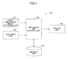
- FIG. 1 is a schematic diagram showing a three-dimensional model modification system 100 according to one embodiment of the present invention.
- the three-dimensional model modification system 100 includes a three-dimensional model capturing unit 101 that captures a three-dimensional model representing an arbitrary object for the system.
- the three-dimensional model refers to a three-dimensional figure defined by plural surfaces, consisting of free-form surfaces generated by, for example, a CAD system.
- the three-dimensional model modification system 100 further includes a user input unit 102 that receives operational inputs from a user.
- the user input unit 102 includes one or more user input devices such as a mouse, a track pad, and a keyboard.
- the three-dimensional model modification system 100 still further includes a memory unit 103 that records and stores one or more skeleton lines.
- the memory unit 103 may be any recording medium.
- plural skeleton line data e.g. for 1BOX/2BOX, for pickup, and for 3BOX
- a three-dimensional model representing the entire outline of a vehicle are previously recorded in the memory unit 103.
- the three-dimensional model modification system 100 still further includes a display unit 104 that provides a visual display of the base curves (explained below) before and after modification, a group of points (explained below) before and after modification, and a modification process of the base curves to the user.
- the display unit 104 may be, for example, a display device.
- the three-dimensional model modification system 100 still further includes an arithmetic and control unit 105 that performs various arithmetic processing explained below and totally controls each of the above-mentioned units.
- the arithmetic and control unit may be, for example, a Central Processing Unit (CPU).
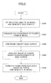
- FIG. 2 is a flowchart showing a processing flow of the three-dimensional model modification system 100 according to the embodiment of the present invention.
- FIGS. 3 through 6 are pattern diagrams each schematically showing a process of the steps in FIG. 2 .
- the arithmetic and control unit 105 extracts the skeleton lines ( FIG. 3(b) ) which are most appropriate for the three-dimensional model from the memory unit 103, and fits the extracted skeleton lines to the three-dimensional model (step 201 in FIG. 2 ).
- This fitting process can be carried out by using a conventional curve modification method (for example, by moving the control points).
- the skeleton lines are modified so as to contact at least a part of a surface of the three-dimensional model without changing the three-dimensional model or its topology ( FIG. 3(c) ).
- the skeleton lines are defined by plural of curves, or free-form lines. Therefore, the skeleton lines are constrained by each other under relatively low restraint conditions, and it is possible to reduce the number of arithmetic steps and to facilitate the operations to modify the three-dimensional model.
- the skeleton line that is modified so as to be fit in a three-dimensional model to be modified is referred to as a base curve of the three-dimensional model.
- the arithmetic and control unit 105 controls the display unit 104 to show the generated base curves to the user.
- the arithmetic and control unit 105 forms polygons from the free-form surfaces ( FIG. 4(a) ) of the three-dimensional model captured by the three-dimensional model capturing unit 101 and generates a group of points ( FIG. 4(b) ) representing the free-form surfaces (step 202 in FIG. 2 ).
- a specific method for generating a group of points from surfaces is omitted as it is known to a person skilled in the art and also is achieved by a function of a commercially available CAD system.
- the arithmetic and control unit 105 modifies the base curves generated in step 201 based on the user's operations input by way of the user input unit 102 (step 203 in FIG. 2 ).
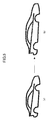
- FIG. 5 shows one example where, according to the user's instruction (with respect to the extending direction and the value), the base curves (a), generated in step 201 (before modification), are modified so that the size of a vehicle is extended only in the longitudinal direction, while keeping the vehicle topology substantially unchanged, to generate the base curves (b) that have been modified.
- the arbitrary modification of the base curves can be achieved by a method similar to that in step 201.
- a parametric function of commercially available CAD software it is easy to generate a modified base curve by specifying and changing, for example, a certain length of a curve only.
- the arithmetic and control unit 105 controls the display unit 104 to show the modified base curves ( FIG. 5(b) ) to the user.
- a modification process that is, changing status corresponding to each input
- base curves before modification FIG. 5(a)
- base curves after modification FIG. 5(b)
- the user inputs an instruction to modify the base curves so that the user can have an image of the base curves that the user wishes to generate.
- the arithmetic and control unit 105 displaces the group of points, representing the three-dimensional model to be modified and generated in step 202 (step 204 in FIG. 2 ), according to the displacements of the base curves based on the modification of the base curves in FIG.5 .
- the group of points ( FIG. 6(b) ) is determined when the group of points ( FIG. 6(a) ) generated in step 202 is displaced in the same manner as in a case where the base curves before modification ( FIG. 5(a) ) displaced to the base curves after modification (FIG. a(b)).
- the arithmetic and control unit 105 forms polygons from the group of points thus modified to generate a group of surfaces, that is, a modified three-dimensional model (step 205 in FIG. 2 ).
- first and second methods are tentatively called a least square method and a gravity force method, respectively.
- the position of each point in a group of points is determined in a small local portion as shown in FIG. 7 for simplifying purposes in this case when each point of the group of points before modification is displaced in accordance with the displacement of the base curve from the base curve F to the base curve T.
- a displacement function D(X) to minimize above M is determined.
- reference symbol A i,j,k denotes a B-Spline control point and a unknown value.
- reference symbols u_ijk, v_ijk, w_ijk are Greville parameters for the control points A i,j,k , respectively.
- the displacement function D(X), minimizing the value of M in Equation 1 is used as a displacement function when the group of points before modification ( FIG. 6(a) ) is displaced to the group points after modification ( FIG. 6(b) ).
- each point of a group of points, representing a three-dimensional model is influenced depending on the distance to a base curve, and a point closer to the base curve will be displaced further.
- the position of each point in a group of points after modification is determined in a small local portion as shown in FIG. 8 when each point of the group of points before modification is displaced in accordance with the displacement of the base curve from the base curve F to the base curve T.
- a line-length parameter of the base curve F that is not yet modified with respect to a point X of a group of points, or a foot-of-a-perpendicular parameter from the point X to the base line F before modification is expressed as S f (x).
- the base curve F can be expressed as C f (S f (X)) as a function of the parameter S f (x).
- reference symbols L f and L t denote line lengths of C f and C t , respectively.
- each point of the group of points before modification is displaced according to the displacement function D(C f (S f (X))). Namely, the point X is displaced to the point (X+ D(C f (S f (X)))).
- FIG. 9 In an actual situation, there are plural base curves F that are not yet modified and plural base curves T after modification. Thus, the next case shown in FIG. 9 is considered.
- FIG. 9 among the cases where two or more base curves F and two or more base curve T exist, the simplest case is shown where there are two base curves F and two base curves T.
- a point that is on the first base curve C f1 before modification and that corresponds to a point X can be expressed as C f1 (S f1 ), and the displacement vector of the point C f1 (S f1 ) can be expressed as D(X,C f1 (S f1 )).
- a point that is on the second base curve C f2 before modification and that corresponds to a point X can be expressed as C f2 (S f2 )
- the displacement vector of the point C f2 (S f2 ) can be expressed as D(X,C f2 (S f2 )).
- a weighting is applied to the displacement vector D(X,C fi (S fi )).
- a weighting function applied to the displacement vector D(X,C fi (S fi )) is expressed as W(X, C fi (S fi ).
- a perpendicular parameter is used to determine the point that corresponds to the point X and that is on the base curve F before modification.
- a perpendicular cannot be drawn or where an inconvenient situation occurs depending on the number of curves even if each of them is a curve when viewed separately.
- an integration model is considered below.
- one base curve F before modification (i th base curve C fi that is not yet modified) is divided into N minute lines ⁇ S.
- the solid line represents the weighting function of equation 11
- the dotted line represents the weighting function in which a value of weighting is inversely proportional to the square of the distance.
- the function F(d) draws a curve line smoothly connecting in the section d s ⁇ d ⁇ d f .
- an arbitrary line configuring the base curves may be duplicated into lines to double the gravity force from the line to increase the restraint force of the section.
- the gravity force model by defining the gravity force model function and duplicating the base curve as explained above, when the polygons are formed from a group of points before modification to generate the surfaces, a group of the surfaces thus generated are apt to be relatively closer to the base curves that have been modified.
- step 204 The methods for displacing the group of points in step 204 (S204) are explained above by citing two concrete examples.
- the workload of the arithmetic processing can be lowered when the group of lines and the group of points are modified compared to when the group of surfaces which surfaces restrain each other is modified.
- the base curves consisting of plural curves are fit to the three-dimensional model that is a three-dimensional figure defined by plural surfaces, the group of points is generated from the three-dimensional model, and the group of points representing the three-dimensional model is displaced based on the desired modification applied to the base curves. Therefore, it is possible to, while considering the design intention and restraint conditions of the three-dimensional model, carry out the modification process in a shorter time and to facilitate the operations of the process.
- the present invention can be widely used in a three-dimensional model modification system for modifying a three-dimensional model defined by plural surfaces, a method of the same, a computer-readable program of the same, and a computer-readable recording medium storing the program.
- An object of the three-dimensional model is not limited to a vehicle but may be any industrial product.
Landscapes
- Engineering & Computer Science (AREA)
- Physics & Mathematics (AREA)
- Computer Graphics (AREA)
- Software Systems (AREA)
- General Physics & Mathematics (AREA)
- Theoretical Computer Science (AREA)
- Architecture (AREA)
- Computer Hardware Design (AREA)
- General Engineering & Computer Science (AREA)
- Geometry (AREA)
- Processing Or Creating Images (AREA)
Claims (5)
- Système de modification de modèle tridimensionnel destiné à modifier un modèle tridimensionnel, défini par une pluralité de surfaces et représentant un objet arbitraire, dans lequel l'objet du modèle tridimensionnel est un produit industriel tel qu'un véhicule,
le système comprenant :une unité de génération de courbes de base (105) adaptant des lignes d'ossature, qui représentent un contour approximatif préenregistré de l'objet, au modèle tridimensionnel de l'objet à modifier, et générant des courbes de base sur la base desdites lignes d'ossature, qui représentent un contour approximatif du modèle tridimensionnel à modifier ;une première unité de formation de polygones (105) formant des polygones à partir de surfaces de forme libre du modèle tridimensionnel à modifier, et générant un groupe de points qui représente les surfaces de forme libre du modèle tridimensionnel à modifier ;une unité de modification de courbes de base (105) modifiant arbitrairement les courbes de base du modèle tridimensionnel, générées par l'unité de génération de courbes de base, selon une instruction provenant d'un opérateur ;une unité de détermination / déplacement de groupes de points (105) déplaçant le groupe de points, généré par la première unité de formation de polygones et représentant le modèle tridimensionnel à modifier, sur la base de déplacements de courbes de base à partir des courbes de base, générées par l'unité de génération de courbes de base avant modification arbitraire, vers les courbes de base, générées par l'unité de modification de courbes de base après modification arbitraire, et déterminant le groupe de points modifié correspondant aux courbes de base, générées par l'unité de modification de courbes de base après modification arbitraire ;
dans lequel, en qualité de procédé de calcul pour déplacer le groupe de points après le déplacement, un procédé des moindres carrés, ou un procédé de force de gravité, est utilisé,dans lequel, dans le cadre du procédé des moindres carrés, une fonction de déplacement, D(X), est définie en utilisant des fonctions à base de courbe B-spline, dans lequel un point Xi(=xi, yi, zi) situé sur une courbe de base F avant modification est déplacé vers un point situé sur une courbe de base T après modification, selon un vecteur de déplacement Vi (=(ui, Vi, Wi)) (i=1, 2, ..., N) ;chaque point X dans un groupe de points est déplacé selon la fonction de déplacement D(x) :
dans lequel la fonction de déplacement D(X) est déterminée de manière à minimiser M, et un coefficient a est défini
dans l'équation (1) ci-dessus, la fonction de déplacement D(X) est définie comme suit en utilisant des fonctions à base de courbe B-spline Ni(x), Ni(y), et Ni(z) : le symbole de référence Ai,j,k désigne une valeur inconnue et un point de contrôle de courbe B-spline ;dans l'équation (1), le symbole de référence E représente l'énergie empêchant un glissement, défini comme suit :

dans lequel les symboles de référence u_ijk, v_ijk, w_ijk sont des paramètres de Greville pour les points de contrôle Ai,j,k, respectivement, etdans le cadre du procédé de force de gravité, chaque point d'un groupe de points, représentant un modèle tridimensionnel, est influencé en fonction de la distance d jusqu'à une courbe de base, et un point plus proche de la courbe de base est en outre déplacé, dans lequel une fonction de pondération W est utilisée dans laquelle un point séparé dans une certaine mesure d'une courbe de base est totalement exempt de l'influence de la courbe de base, selon l'équation ci-dessous :


dans lequel la fonction F(d) dessine une ligne courbe offrant une connexion lisse dans la section ds < d ≦ df,
etune seconde unité de formation de polygones (105) formant de nouveaux polygones à partir du groupe de points modifié déterminé par l'unité de détermination / déplacement de groupes de points, et générant un modèle tridimensionnel modifié défini par une pluralité de surfaces générée par lesdits nouveaux polygones. - Système de modification de modèle tridimensionnel selon la revendication 1, le système comprenant en outre :une unité d'affichage montrant à l'opérateur les courbes de base avant et après la modification, le groupe de points avant et après la modification, et une modification des courbes de base modifiées par l'unité de modification de courbes de base.
- Procédé de modification de modèle tridimensionnel mis en oeuvre par ordinateur, destiné à modifier un modèle tridimensionnel, défini par une pluralité de surfaces et représentant un objet arbitraire, dans lequel l'objet du modèle tridimensionnel est un produit industriel tel qu'un véhicule, le procédé comportant les étapes ci-dessous :une étape de génération de courbes de base consistant à adapter des lignes d'ossature, qui représentent un contour approximatif préenregistré de l'objet, à un modèle tridimensionnel à modifier, et à générer des courbes de base qui représentent un contour approximatif du modèle tridimensionnel à modifier ;une première étape de formation de polygones consistant à former des polygones à partir de surfaces de forme libre du modèle tridimensionnel à modifier, et à générer un groupe de points qui représente les surfaces de forme libre du modèle tridimensionnel à modifier ;une étape de modification de courbes de base consistant à modifier arbitrairement les courbes de base du modèle tridimensionnel, générées par l'étape de génération de courbes de base, selon une instruction provenant d'un opérateur ;une étape de détermination / déplacement de groupes de points consistant à déplacer le groupe de points, généré par la première étape de formation de polygones et représentant le modèle tridimensionnel à modifier, sur la base de déplacements de courbes de base à partir des courbes de base, générées par l'étape de génération de courbes de base avant modification arbitraire, vers les courbes de base, générées par l'étape de modification de courbes de base après modification arbitraire, et à déterminer un groupe de points modifié correspondant aux courbes de base, générées par l'étape de modification de courbes de base après modification arbitraire ;dans lequel, en qualité de procédé de calcul pour déplacer le groupe de points après le déplacement, un procédé des moindres carrés, ou un procédé de force de gravité, est utilisé,dans lequel, dans le cadre du procédé des moindres carrés, une fonction de déplacement, D(X), est définie en utilisant des fonctions à base de courbe B-spline, dans lequel un point Xi(=xi, yi, zi) situé sur une courbe de base F avant modification est déplacé vers un point situé sur une courbe de base T après modification, selon un vecteur de déplacement Vi (=(ui, Vi, Wi)) (i=1, 2, ..., N) ;chaque point X dans un groupe de points est déplacé selon la fonction de déplacement D(x) :

dans lequel la fonction de déplacement D(X) est déterminée de manière à minimiser M, et un coefficient a est définidans l'équation (1) ci-dessus, la fonction de déplacement D(X) est définie comme suit en utilisant des fonctions à base de courbe B-spline Ni(x), Ni(y), et Ni(z) : le symbole de référence Ai,j,k désigne une valeur inconnue et un point de contrôle de courbe B-spline ;dans l'équation (1), le symbole de référence E représente l'énergie empêchant un glissement, défini comme suit :

dans lequel les symboles de référence u_ijk, v_ijk, w_ijk sont des paramètres de Greville pour les points de contrôle Ai,j,k, respectivement ; etdans le cadre du procédé de force de gravité, chaque point d'un groupe de points, représentant un modèle tridimensionnel, est influencé en fonction de la distance d jusqu'à une courbe de base, et un point plus proche de la courbe de base est en outre déplacé, dans lequel une fonction de pondération W est utilisée dans laquelle un point séparé dans une certaine mesure d'une courbe de base est totalement exempt de l'influence de la courbe de base, selon l'équation ci-dessous :


dans lequel la fonction F(d) dessine une ligne courbe offrant une connexion lisse dans la section ds < d ≦ df,
etune seconde étape de formation de polygones consistant à former des polygones à partir du groupe de points modifié déterminé par l'étape de détermination / déplacement de groupes de points, et à générer un modèle tridimensionnel modifié défini par une pluralité de surfaces. - Procédé de modification de modèle tridimensionnel selon la revendication 3, le procédé comprenant en outre l'étape ci-dessous :une étape d'affichage consistant à montrer à l'opérateur les courbes de base avant et après la modification, le groupe de points avant et après la modification, et une modification des courbes de base modifiées par l'étape de modification de courbes de base.
- Programme de modification de modèle tridimensionnel lisible par ordinateur amenant un ordinateur, lorsqu'il est exécuté, à mettre en oeuvre les étapes du procédé selon la revendication 3 ou 4.
Applications Claiming Priority (2)
| Application Number | Priority Date | Filing Date | Title |
|---|---|---|---|
| JP2005107722A JP3829862B1 (ja) | 2005-04-04 | 2005-04-04 | 3次元モデル変形システム及びプログラム |
| PCT/JP2006/306332 WO2006106686A1 (fr) | 2005-04-04 | 2006-03-28 | Systeme de deformation de modele en trois dimensions, procede et programme lisible par machine, et support de stockage lisible par machine stockant ledit programme |
Publications (3)
| Publication Number | Publication Date |
|---|---|
| EP1868121A1 EP1868121A1 (fr) | 2007-12-19 |
| EP1868121A4 EP1868121A4 (fr) | 2009-04-22 |
| EP1868121B1 true EP1868121B1 (fr) | 2014-09-10 |
Family
ID=37073252
Family Applications (1)
| Application Number | Title | Priority Date | Filing Date |
|---|---|---|---|
| EP06730280.2A Expired - Lifetime EP1868121B1 (fr) | 2005-04-04 | 2006-03-28 | Systeme de modification de modele en trois dimensions, procede et programme lisible par machine, et support de stockage lisible par machine stockant ledit programme |
Country Status (7)
| Country | Link |
|---|---|
| US (1) | US7924277B2 (fr) |
| EP (1) | EP1868121B1 (fr) |
| JP (1) | JP3829862B1 (fr) |
| KR (1) | KR100907710B1 (fr) |
| CN (1) | CN100535910C (fr) |
| CA (1) | CA2598615C (fr) |
| WO (1) | WO2006106686A1 (fr) |
Families Citing this family (14)
| Publication number | Priority date | Publication date | Assignee | Title |
|---|---|---|---|---|
| JP3829862B1 (ja) * | 2005-04-04 | 2006-10-04 | トヨタ自動車株式会社 | 3次元モデル変形システム及びプログラム |
| CN101378591B (zh) | 2007-08-31 | 2010-10-27 | 华为技术有限公司 | 终端移动时安全能力协商的方法、系统及装置 |
| KR101125901B1 (ko) * | 2009-12-09 | 2012-03-21 | 한국항공우주산업 주식회사 | 컴퓨터-지원 설계 시스템에서 복잡 곡면 기계 가공품의 선직면 생성 및 검증 방법 |
| CN101872490A (zh) * | 2010-07-02 | 2010-10-27 | 北京理工大学 | 一种改进的坐标轴方向突变下的三维模型变形方法 |
| CN101894389A (zh) * | 2010-07-02 | 2010-11-24 | 北京理工大学 | 一种基于旋转角插值的三维模型扭转变形方法 |
| US8723863B2 (en) * | 2010-07-07 | 2014-05-13 | Siemens Product Lifecycle Management Software Inc. | Data processing system with construction geometry |
| EP2849166B1 (fr) * | 2012-05-09 | 2020-08-26 | Toyota Jidosha Kabushiki Kaisha | Dispositif d'aide à la conduite |
| KR101465483B1 (ko) * | 2013-12-23 | 2014-11-26 | 한국건설기술연구원 | Lod데이터를 구성하는 bim데이터 처리 시스템 |
| KR20150081992A (ko) * | 2014-01-07 | 2015-07-15 | 한국전자통신연구원 | 건축물 구성요소 템플릿 생성 방법, 프리미티브 생성 방법, 및 건축물 구성요소 모델링 장치 |
| WO2016198929A1 (fr) * | 2015-06-12 | 2016-12-15 | Mathur Ashok Chand | Procédé et appareil pour imprimante 3d beaucoup plus rapide |
| JP6634317B2 (ja) * | 2016-03-16 | 2020-01-22 | 日本ユニシス株式会社 | 形状変形装置および形状変形用プログラム |
| JP6727932B2 (ja) * | 2016-06-01 | 2020-07-22 | 日本ユニシス株式会社 | 点群面張りによる曲面生成装置および曲面生成用プログラム |
| JP7030010B2 (ja) * | 2018-05-09 | 2022-03-04 | 日本放送協会 | 立体映像奥行き圧縮装置および立体映像奥行き圧縮プログラム |
| US11983819B2 (en) * | 2022-05-25 | 2024-05-14 | Verizon Patent And Licensing Inc. | Methods and systems for deforming a 3D body model based on a 2D image of an adorned subject |
Citations (1)
| Publication number | Priority date | Publication date | Assignee | Title |
|---|---|---|---|---|
| EP1868121A1 (fr) * | 2005-04-04 | 2007-12-19 | Toyota Jidosha Kabushiki Kaisha | Systeme de deformation de modele en trois dimensions, procede et programme lisible par machine, et support de stockage lisible par machine stockant ledit programme |
Family Cites Families (12)
| Publication number | Priority date | Publication date | Assignee | Title |
|---|---|---|---|---|
| JPH09223242A (ja) | 1996-02-16 | 1997-08-26 | Matsushita Electric Ind Co Ltd | アニメーション作成装置 |
| JP3241266B2 (ja) * | 1996-06-03 | 2001-12-25 | 本田技研工業株式会社 | 3次元cadシステム |
| JP4201359B2 (ja) | 1997-04-16 | 2008-12-24 | 本田技研工業株式会社 | デザイン作成装置 |
| US6204860B1 (en) | 1998-07-02 | 2001-03-20 | Silicon Graphics, Inc. | Method and apparatus for geometric model deformation using wires |
| JP2002015310A (ja) | 2000-06-30 | 2002-01-18 | Minolta Co Ltd | 点群に面をフィッティングする方法およびモデリング装置 |
| JP3954318B2 (ja) | 2001-03-09 | 2007-08-08 | 独立行政法人科学技術振興機構 | 3次元モデル変形システム |
| JP3753625B2 (ja) | 2001-04-03 | 2006-03-08 | 株式会社国際電気通信基礎技術研究所 | 表情アニメーション生成装置および表情アニメーション生成方法 |
| US6919888B1 (en) * | 2001-07-03 | 2005-07-19 | Adobe Systems Incorporated | Computer drawing shape manipulation with envelope meshes |
| JP2003030254A (ja) | 2001-07-17 | 2003-01-31 | Toyota Motor Corp | 3次元形状モデル変形方法 |
| JP3973992B2 (ja) | 2002-08-09 | 2007-09-12 | 独立行政法人科学技術振興機構 | 3次元モデル変形システム |
| US7653517B2 (en) * | 2003-04-15 | 2010-01-26 | Toyota Jidosha Kabushiki Kaisha | Design data generating apparatus and design data generating method |
| US7440877B2 (en) * | 2004-03-12 | 2008-10-21 | General Motors Corporation | System and method for morphable model design space definition |
-
2005
- 2005-04-04 JP JP2005107722A patent/JP3829862B1/ja not_active Expired - Fee Related
-
2006
- 2006-03-28 EP EP06730280.2A patent/EP1868121B1/fr not_active Expired - Lifetime
- 2006-03-28 CA CA2598615A patent/CA2598615C/fr not_active Expired - Fee Related
- 2006-03-28 KR KR1020077022523A patent/KR100907710B1/ko not_active Expired - Fee Related
- 2006-03-28 CN CNB2006800094642A patent/CN100535910C/zh not_active Expired - Fee Related
- 2006-03-28 US US11/816,187 patent/US7924277B2/en not_active Expired - Fee Related
- 2006-03-28 WO PCT/JP2006/306332 patent/WO2006106686A1/fr not_active Ceased
Patent Citations (1)
| Publication number | Priority date | Publication date | Assignee | Title |
|---|---|---|---|---|
| EP1868121A1 (fr) * | 2005-04-04 | 2007-12-19 | Toyota Jidosha Kabushiki Kaisha | Systeme de deformation de modele en trois dimensions, procede et programme lisible par machine, et support de stockage lisible par machine stockant ledit programme |
Also Published As
| Publication number | Publication date |
|---|---|
| US20090207168A1 (en) | 2009-08-20 |
| JP2006285858A (ja) | 2006-10-19 |
| CN101147150A (zh) | 2008-03-19 |
| JP3829862B1 (ja) | 2006-10-04 |
| EP1868121A1 (fr) | 2007-12-19 |
| EP1868121A4 (fr) | 2009-04-22 |
| CN100535910C (zh) | 2009-09-02 |
| CA2598615A1 (fr) | 2006-10-12 |
| KR20070108414A (ko) | 2007-11-09 |
| US7924277B2 (en) | 2011-04-12 |
| CA2598615C (fr) | 2011-08-09 |
| WO2006106686A1 (fr) | 2006-10-12 |
| KR100907710B1 (ko) | 2009-07-14 |
Similar Documents
| Publication | Publication Date | Title |
|---|---|---|
| US7643026B2 (en) | NURBS surface deformation apparatus and the method using 3D target curve | |
| EP1868121A1 (fr) | Systeme de deformation de modele en trois dimensions, procede et programme lisible par machine, et support de stockage lisible par machine stockant ledit programme | |
| US20080278480A1 (en) | Image processing method and image processing apparatus | |
| EP3674930A1 (fr) | Conception d'une pièce mécanique | |
| CN111105501B (zh) | B-rep皮肤的3d设计 | |
| JP4721764B2 (ja) | コンピュータ利用設計モデル(cad)の変形 | |
| WO1998053427A1 (fr) | Appareil et procedes d'interpolation et de metamorphose d'objets au moyen de squelettes | |
| US8325183B2 (en) | System and method for determining a position for an addendum mesh node | |
| Cheung et al. | Incremental rendering of deformable trimmed NURBS surfaces | |
| CN115917457A (zh) | 具有过滤以促进2.5轴减材制造过程的计算机辅助生成式设计 | |
| Lefebvre et al. | 3D morphing for generating intermediate roughing levels in multi-axis machining | |
| CN111444674B (zh) | 文字变形方法、介质及计算机设备 | |
| JPH0511828A (ja) | フイレツト曲面創成位置の指定方法 | |
| JP5614953B2 (ja) | 画像処理装置および画像処理方法 | |
| JP4102057B2 (ja) | 3次元製品作成方法及びその装置、3次元製品加工用モデル作成プログラム | |
| JP4745699B2 (ja) | 3次元モデル表示制御プログラム及び3次元モデル表示制御方法 | |
| JPH0991332A (ja) | 断面データの作成および修正方法とその装置 | |
| Lanquetin et al. | Generalized SCODEF deformations on subdivision surfaces | |
| KR100427180B1 (ko) | 기하도형의 모핑방법 | |
| JP4235088B2 (ja) | フィレット面生成方法及びプログラム | |
| JPH07134779A (ja) | 掃引体図形生成装置 | |
| JP2866783B2 (ja) | フィレット面生成装置 | |
| JPH0887585A (ja) | 図形データの階層的近似化方法 | |
| Lanquetin¹ª et al. | Constrained free form deformation on subdivision surfaces | |
| JPH06118940A (ja) | 画像データ編集装置および方法 |
Legal Events
| Date | Code | Title | Description |
|---|---|---|---|
| PUAI | Public reference made under article 153(3) epc to a published international application that has entered the european phase |
Free format text: ORIGINAL CODE: 0009012 |
|
| 17P | Request for examination filed |
Effective date: 20070813 |
|
| AK | Designated contracting states |
Kind code of ref document: A1 Designated state(s): DE FR IT |
|
| DAX | Request for extension of the european patent (deleted) | ||
| RBV | Designated contracting states (corrected) |
Designated state(s): DE FR IT |
|
| A4 | Supplementary search report drawn up and despatched |
Effective date: 20090320 |
|
| 17Q | First examination report despatched |
Effective date: 20090821 |
|
| RAP1 | Party data changed (applicant data changed or rights of an application transferred) |
Owner name: TOYOTA JIDOSHA KABUSHIKI KAISHA |
|
| RIC1 | Information provided on ipc code assigned before grant |
Ipc: G06F 17/50 20060101AFI20131119BHEP Ipc: G06T 19/20 20110101ALI20131119BHEP |
|
| GRAP | Despatch of communication of intention to grant a patent |
Free format text: ORIGINAL CODE: EPIDOSNIGR1 |
|
| INTG | Intention to grant announced |
Effective date: 20140211 |
|
| GRAS | Grant fee paid |
Free format text: ORIGINAL CODE: EPIDOSNIGR3 |
|
| RIN1 | Information on inventor provided before grant (corrected) |
Inventor name: HASHIMOTO, TAKAYA, Inventor name: MISAWA, HITOSHI, Inventor name: ISHIDA, JUNJI, Inventor name: HATTORI,KAZUYUKI, Inventor name: KOTANI, TADASHI, |
|
| GRAA | (expected) grant |
Free format text: ORIGINAL CODE: 0009210 |
|
| AK | Designated contracting states |
Kind code of ref document: B1 Designated state(s): DE FR IT |
|
| RIN1 | Information on inventor provided before grant (corrected) |
Inventor name: HATTORI, KAZUYUKI Inventor name: KOTANI, TADASHI, Inventor name: ISHIDA, JUNJI Inventor name: HASHIMOTO, TAKAYA, Inventor name: MISAWA, HITOSHI |
|
| REG | Reference to a national code |
Ref country code: DE Ref legal event code: R096 Ref document number: 602006043003 Country of ref document: DE Effective date: 20141023 |
|
| REG | Reference to a national code |
Ref country code: DE Ref legal event code: R084 Ref document number: 602006043003 Country of ref document: DE |
|
| REG | Reference to a national code |
Ref country code: DE Ref legal event code: R084 Ref document number: 602006043003 Country of ref document: DE Effective date: 20141219 |
|
| REG | Reference to a national code |
Ref country code: FR Ref legal event code: PLFP Year of fee payment: 10 |
|
| PGFP | Annual fee paid to national office [announced via postgrant information from national office to epo] |
Ref country code: IT Payment date: 20150220 Year of fee payment: 10 Ref country code: DE Payment date: 20150324 Year of fee payment: 10 |
|
| PGFP | Annual fee paid to national office [announced via postgrant information from national office to epo] |
Ref country code: FR Payment date: 20150309 Year of fee payment: 10 |
|
| REG | Reference to a national code |
Ref country code: DE Ref legal event code: R097 Ref document number: 602006043003 Country of ref document: DE |
|
| PLBE | No opposition filed within time limit |
Free format text: ORIGINAL CODE: 0009261 |
|
| STAA | Information on the status of an ep patent application or granted ep patent |
Free format text: STATUS: NO OPPOSITION FILED WITHIN TIME LIMIT |
|
| 26N | No opposition filed |
Effective date: 20150611 |
|
| REG | Reference to a national code |
Ref country code: DE Ref legal event code: R119 Ref document number: 602006043003 Country of ref document: DE |
|
| REG | Reference to a national code |
Ref country code: FR Ref legal event code: ST Effective date: 20161130 |
|
| PG25 | Lapsed in a contracting state [announced via postgrant information from national office to epo] |
Ref country code: DE Free format text: LAPSE BECAUSE OF NON-PAYMENT OF DUE FEES Effective date: 20161001 Ref country code: FR Free format text: LAPSE BECAUSE OF NON-PAYMENT OF DUE FEES Effective date: 20160331 |
|
| PG25 | Lapsed in a contracting state [announced via postgrant information from national office to epo] |
Ref country code: IT Free format text: LAPSE BECAUSE OF NON-PAYMENT OF DUE FEES Effective date: 20160328 |