EP1868150A2 - Planificateur d'utilisation de grue - Google Patents
Planificateur d'utilisation de grue Download PDFInfo
- Publication number
- EP1868150A2 EP1868150A2 EP07005795A EP07005795A EP1868150A2 EP 1868150 A2 EP1868150 A2 EP 1868150A2 EP 07005795 A EP07005795 A EP 07005795A EP 07005795 A EP07005795 A EP 07005795A EP 1868150 A2 EP1868150 A2 EP 1868150A2
- Authority
- EP
- European Patent Office
- Prior art keywords
- crane
- data
- load
- planning unit
- mission
- Prior art date
- Legal status (The legal status is an assumption and is not a legal conclusion. Google has not performed a legal analysis and makes no representation as to the accuracy of the status listed.)
- Granted
Links
Images


Classifications
-
- B—PERFORMING OPERATIONS; TRANSPORTING
- B66—HOISTING; LIFTING; HAULING
- B66C—CRANES; LOAD-ENGAGING ELEMENTS OR DEVICES FOR CRANES, CAPSTANS, WINCHES, OR TACKLES
- B66C23/00—Cranes comprising essentially a beam, boom, or triangular structure acting as a cantilever and mounted for translatory of swinging movements in vertical or horizontal planes or a combination of such movements, e.g. jib-cranes, derricks, tower cranes
- B66C23/88—Safety gear
- B66C23/90—Devices for indicating or limiting lifting moment
- B66C23/905—Devices for indicating or limiting lifting moment electrical
-
- G—PHYSICS
- G06—COMPUTING OR CALCULATING; COUNTING
- G06Q—INFORMATION AND COMMUNICATION TECHNOLOGY [ICT] SPECIALLY ADAPTED FOR ADMINISTRATIVE, COMMERCIAL, FINANCIAL, MANAGERIAL OR SUPERVISORY PURPOSES; SYSTEMS OR METHODS SPECIALLY ADAPTED FOR ADMINISTRATIVE, COMMERCIAL, FINANCIAL, MANAGERIAL OR SUPERVISORY PURPOSES, NOT OTHERWISE PROVIDED FOR
- G06Q10/00—Administration; Management
- G06Q10/06—Resources, workflows, human or project management; Enterprise or organisation planning; Enterprise or organisation modelling
Definitions
- the invention relates to a crane operation planner, with which the use of a crane, in particular a crawler crane, can be planned in advance.
- Known crane deployment planners are usually software products which are installed at the respective customer and run on the computer system. This results in a very high administrative effort for the care and maintenance of the many crane application planners installed at the customer's site, if eg. B. new crane components new furnishing options for the cranes. It is of particular disadvantage that the respective data for crane configuration and the possible crane positions must be determined in advance for each configuration and crane position and then transmitted as tabular data on each installed at the customer crane application planner. In addition, the known crane deployment planners are often complicated to operate and do not adequately support the user in the planning and in the subsequent actual implementation of the planned deployment.
- Object of the present invention is therefore to provide a crane deployment planner, which can be maintained with little effort, which is easy to use and thereby facilitates the implementation of the use.
- a crane deployment planner according to claim 1.
- This has a central planning unit, which comprises a central database with data on the usable cranes and a calculation module for calculating the load moments occurring during use. Simulations and calculations of the missions are performed by the central planning unit, while the input and output of data takes place via clients, whereby the clients communicate with the central planning unit via the Internet.
- Commercially available Internet browsers can be used to input and output data to the clients.
- the customer no additional software must be installed on its clients, as the complex planning unit is centrally located at the provider of crane dispatch planner. This considerably reduces the maintenance effort since only the data of the central database has to be maintained or only the calculation module of the central planning unit has to be kept up to date.
- the database in addition to the data on the cranes that can be used, the database also contains data on deployable crane components for equipping the cranes. In modern crane systems, this can be very considerable amounts of data, so that central storage of this data is of great advantage.
- the cranes can then be selected and equipped with the necessary crane components to plan an operation.
- the database advantageously contains both data on all possible cranes and crane components that can be used and customer-specific data for the cranes and crane components that are in each case available in the customer's fleet.
- the customer can determine in advance whether a planned use can be carried out with his own material, or whether, if necessary, new crane components or cranes are needed.
- the database includes three-dimensional geometric data and physical properties of the usable cranes and the deployable crane components. Through this data, the use can be planned and a realistic simulation can be created.
- the calculation module uses a physical model of the cranes used and Kranrüstzunot to calculate the load moments occurring during use and sets maximum load moments.
- a physical model of the cranes used has the great advantage that corresponding data must not be created in advance for any crane position of any crane configuration and then stored in tabular values, but that the values occurring during use can be determined and output in real time . It is also possible to dispense with an interpolation of the data in intermediate positions of the crane, which increases the accuracy and reliability of the values.
- the physical model thus enables a real time calculation of the load moment limitation (LMB), ie an output of the structural and tipping loads, the ground pressure as well as other relevant data on the respective crane configurations in the corresponding crane positions during the planned use.
- LMB load moment limitation
- the calculation module of the central planning unit uses the same physical model as the load moment limitation of the crane used. If both the load moment limitation permanently installed in the crane used and the calculation module use the same physical model, it is ensured that the data calculated during the planning of the operation coincide with the load moment limitation data occurring during the actual use, so that the customer is angry Surprises for sure.
- the planning unit automatically determines the applicable crane types and crane setup states.
- a simple search and an expert search in which a plurality of parameters can be defined are possible.
- the customer only has to enter data for the respective load case, such as the weight of the load, the lift height, and the required lift distance, and the planning unit automatically calculates which crane types and crane set conditions are suitable for this load case.
- the customer knows immediately with which crane equipment state the planned use is possible.
- the orientation of the crane for receiving the load object takes place automatically after determining the crane position and load position.
- a deployment simulating scenario is created for planning the mission.
- the crane and other objects can be positioned in the scenario.
- objects can be defined in the scenario and linked to data and attributes. For this, the name and color of the object can be determined, whether it is a load object and what mass it may have, whether the load is on the hook and which coordinates or dimensions the object has.
- Such a scenario usually includes the crane used, the load object, the environment and possible disruptive objects.
- Simple disturbing objects can advantageously be composed of standard objects such as cuboids, spheres, cones, pyramids, cylinders and prisms. In this way, a realistic simulation of the mission can be carried out and all steps of the deployment can be gone through in the scenario.
- the planning unit uses a three-dimensional model to simulate the mission.
- three-dimensional geometric data of the crane used and the crane components used can be used and their movement can be determined in a three-dimensional scenario.
- the database in addition to the three-dimensional data of the cranes, includes three-dimensional data of possible interfering objects, whereby standard objects can be made available on the one hand and such standard objects can be grouped into larger objects and stored and reused in a user-dependent library on the other hand.
- a common library accessible to all users may also include more complex objects.
- three-dimensional data of objects from external sources. If such three-dimensional data of objects can be imported from external data sources, the customer can, for example, B. own Include CAD data of the load objects or of disturbing objects in the simulation of the load case. This data may then be stored in a user-dependent library as appropriate, although 3-D models may also be used from publicly available sources from the Internet.
- objects in the scenario can be moved individually in the scenario via an input interface of the client, in particular a mouse, or controlled by parameter input.
- the objects can be moved user-friendly and intuitive by "drag and drop” or positioned exactly by the parameter input.
- a collision check between the crane and possible jamming objects and between the crane and the load is carried out during the simulation of the mission.
- it can be determined whether the crane, including the load rope, collides with interfering objects during the planned use, so that the planning can be adapted accordingly in advance of the deployment.
- the load circuit for the leading and trailing edges i. for boom and counterweight or Derrick or ballast car determined and displayed.
- a hatched area is advantageously used in the scenario. This is of great interest to the user, as the load circuits that are important for resource planning can be seen at a glance.
- a grid is inserted along the central axis of the cantilever. This facilitates the planning, as the distances from e.g. of the boom to the faulty object are easy to recognize.
- the center of gravity of the crane is determined and displayed.
- this important value for stability can be quickly identified.
- Such a representation then includes e.g. a 2-D elevation, a side view and a floor plan and the 3-D view, each of these representations can be enlarged.
- individual work steps or scenarios can be stored.
- all application-relevant data can be advantageously stored in projects, with any project as many construction sites and a site as many steps can be saved.
- This means that all crane positions planned for use with a crane can be stored with all relevant data as work steps.
- created graphics and relevant load moment limitation data can be stored.
- a log of all steps of a planned mission is automatically created.
- Such a protocol then contains all the data needed to carry out the mission so that safe and reliable implementation of the mission is possible after planning.
- 3-D viewers are to be installed as a client on which the 3-D representations of the respective scenario can be displayed.
- the customer can design the desired crane configuration himself by selecting the cranes and the crane components and placing them in a three-dimensional model. He can also create and save the scenario by selecting or creating clutter objects and the surrounding structures themselves.
- the 3-D viewer of the customer communicate with the central planning unit via the Internet, so that on the one hand an efficient operation and a constant access to all relevant data is possible, while on the other hand the maintenance costs for the crane operation planner are minimized. This also increases security since all security-relevant data is managed centrally and all security-relevant calculations are carried out in the central planning unit.
- the output of the data generated by the planning unit on the client comprises a three-dimensional representation of a scenario.
- the simulation and calculation of the insert by the central planning unit comprises an automatic alignment of the crane on a load object.
- work steps can be stored and automatically a log of all steps are created.
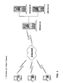
- FIG. 1 shows the structure of the crane service planner.
- the central planning unit which consists of a web server, a database and a LMB server.
- the database stores all relevant data on the cranes that can be used and the crane components that can be used as well as the objects and scenarios created by the customer.
- the LMB server includes the calculation module for calculating the load moments occurring during use, wherein a physical module is used, which corresponds to the load torque limit of the cranes used.
- the web server communicates with the database and LMB server and is connected to the Internet so that it communicates with the client's client over the Internet. Clients only have 3-D viewers installed on their clients, which allows data generated by the planning unit to be displayed. Further software installations on the clients are not necessary as the entire planning is carried out centrally in the planning unit.
- a load specification is defined by entering relevant data on the load object such as load, lifting height, unloading, etc.
- a 3-D world can be created with any interfering objects, which allows a realistic simulation of the crane operation.
- the individual objects in this scenario can be provided with attributes.
- data can also be imported from external data sources.
- 3-D data from CAD models of the customer as well as 3-D models from the Internet (eg for trucks) can be used here.
- These 3-D data can also be integrated into the scenario as load or disturbance objects. This results in the scenario an extremely realistic simulation of the site.
- the program can automatically determine the crane types and crane configurations that are suitable for use in the crane. Thereby it is possible to search for the right crane configuration either by simple search with only one or a few parameters or by expert search, in which several parameters of the load case can be defined. Likewise, a manual compilation of the crane and the equipment is possible, the user can put together three-dimensionally illustrated crane components and cranes in the 3-D viewer to the desired Kranrüstschreib.
- the selected crane will now be displayed three-dimensionally in the scenario.
- various obstructions can also be scheduled and positioned.
- there Crane as well as disturbance and load objects can be easily moved with the mouse in the scenario, which allows a particularly simple and intuitive operation.
- the individual objects can also be controlled by parameter input.
- the planning unit then automatically calculates the necessary for receiving the load object crane position, with z. B. the rotational position of the superstructure and the angular position of the main boom and the jib can be determined.
- the calculation module with the LMB now determines the corresponding crane data such as tipping load, structural load, ground pressure, utilization, etc. in parallel for each work step and outputs these.
- structural and tipping loads are determined and compared with maximum values which, by using the same load moment limitation as in the crane used, exactly correspond to the values occurring in actual use.
- the load circuit for the front and the rear edge of interference i. Jib and counterweight or derrick or ballast wagon, determined and represented in the scenario as grid area.
- the center of gravity of the crane can also be determined and displayed or output.
- a grid can be displayed directly along the central axis of the boom.
- the grid can be used to define distances, e.g. of the cantilever are taken to the interfering object.
- All work steps can be saved parallel to the crane operation planning and then serve for the automatic creation of a log of the crane operation.
- the data determined by LMB are transmitted via the Internet to the 3-D viewers, where the corresponding scenario with the crane position is three-dimensional is pictured.
- several different views of the working step are displayed simultaneously, such as 2D elevation, side view and floor plan as well as 3-D representation. Each of these views can also be enlarged.
- all relevant data of the work step are displayed.
- a log of all work steps with all relevant LMB data and graphics can be created, which can then be processed step by step during the implementation of the mission.
- a film sequence of all steps can be generated, which thus gives a realistic impression of the operation of the mission.
- FIG. 2 shows by way of example a crane selection, which in this case is a manual selection and compilation.
- the user of the crane crew scheduler selects the corresponding crane with the respective equipment from a list made available by the crane deployment planner.
- This data is then sent from the client to the Web server of the central planning unit where it is received by the Web server and forwarded to the LMB server.
- the LMB server creates the corresponding physical crane model from the crane selection data and saves the crane selection and crane position in the database.
- all relevant data are calculated, stored and sent back to the client via the Web server by the LMB server. The results of the calculation such.
- the LMB values, the position of the booms and the ropes are received by the client and output in the form of 3-D graphics and lists.
- FIG. 3 shows a typical output on the client.
- On the left is a 3-D image showing the crawler crane and load scenario, while on the right there are relevant data such as crane utilization, reach, ground pressure, and boom angles.
- relevant data such as crane utilization, reach, ground pressure, and boom angles.
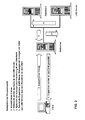
- Figure 4 and Figure 5 show the automatic alignment of the crane after the load.
- this function calculates the rotation angle ⁇ of the rotation of the superstructure and the boom position for the required projection between P1 and P2 as shown in FIG. Since the positions of crane and load object are already given, the rotation angle can be calculated exactly, without the user would have to act here himself.
- the crane 1 consists of an undercarriage 5 with caterpillar drive and a rotatable superstructure 4, on which a main boom 2 is articulated with a needle boom 3.
- the load object 10 is to be lifted via a cable 6 and a pulley 7.
- the rotational position of the superstructure 4 of the crane 1 located at location P1 can be determined automatically with respect to the load object 10 located at location P2.
- the two variables to be determined are the tilt angle of the main boom and the tilt angle of the jib.
- the angles of main boom and jib are automatically changed to achieve the desired reach.
- the jib angle is always offset by 10 ° to the main jib angle to ensure a maximum load capacity of the crane.
- the angle range of the main boom can be limited to z. B. to avoid collisions with interfering objects. If the maximum main boom angle is reached, it is therefore attempted to reach the overhang via the angle of the jib.
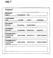
- Figure 7 shows schematically the structure of such a protocol.
- the cover page of the protocol contains general information of the project such as: For example, the date, project name, document title, document number, version, and creator.
- crane data which the crane driver needs for the planned hub.
- these crane data include the crane type, the operating mode, information on the equipment and the load location.
- data are also made on the skin breaker, the jib and the ballast.
- the log contains a step list of all work steps, which contains the most important data for the work steps in tabular form. Since an insert often consists of several steps with different loads, the step list contains all planned work steps with the respective crane position, the angles of rotation as well as the load and hook height in the form of a table. The individual steps are numbered for easy recognition.
- the protocol contains detailed information on the individual work steps.
- utilization, maximum load, ground pressure, collision status are indicated as current and as maximum values. These are displayed in tabular form for each step as well as in a graphic.
- the log contains this detailed information for each individual work step.
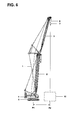
- FIGS. 8 and 9 show graphic representations of two working steps. Both graphs show the crane 1 with main boom 2 and jib 3 in different working positions in a three-dimensional scenario. In addition to the crane 1, the load 10 and interfering objects 20 are indicated, so that the planned work step can be detected at a glance. Also recognizable are the load circuits for the front and the rear interfering edge, which are shown as hatched areas with edges 14 and 15 in the 3-D scenario.
Landscapes
- Engineering & Computer Science (AREA)
- Business, Economics & Management (AREA)
- Human Resources & Organizations (AREA)
- Economics (AREA)
- Strategic Management (AREA)
- Entrepreneurship & Innovation (AREA)
- Operations Research (AREA)
- Physics & Mathematics (AREA)
- Educational Administration (AREA)
- Marketing (AREA)
- Development Economics (AREA)
- Quality & Reliability (AREA)
- Tourism & Hospitality (AREA)
- Game Theory and Decision Science (AREA)
- General Business, Economics & Management (AREA)
- General Physics & Mathematics (AREA)
- Theoretical Computer Science (AREA)
- Mechanical Engineering (AREA)
- Management, Administration, Business Operations System, And Electronic Commerce (AREA)
- Control And Safety Of Cranes (AREA)
- Jib Cranes (AREA)
Applications Claiming Priority (1)
| Application Number | Priority Date | Filing Date | Title |
|---|---|---|---|
| DE102006027202A DE102006027202A1 (de) | 2006-06-12 | 2006-06-12 | Kraneinsatzplaner |
Publications (3)
| Publication Number | Publication Date |
|---|---|
| EP1868150A2 true EP1868150A2 (fr) | 2007-12-19 |
| EP1868150A3 EP1868150A3 (fr) | 2009-12-23 |
| EP1868150B1 EP1868150B1 (fr) | 2011-08-10 |
Family
ID=38421435
Family Applications (1)
| Application Number | Title | Priority Date | Filing Date |
|---|---|---|---|
| EP07005795A Active EP1868150B1 (fr) | 2006-06-12 | 2007-03-21 | Planificateur d'utilisation de grue |
Country Status (4)
| Country | Link |
|---|---|
| US (1) | US8275591B2 (fr) |
| EP (1) | EP1868150B1 (fr) |
| DE (1) | DE102006027202A1 (fr) |
| ES (1) | ES2368948T3 (fr) |
Cited By (6)
| Publication number | Priority date | Publication date | Assignee | Title |
|---|---|---|---|---|
| EP2692684A1 (fr) * | 2012-08-01 | 2014-02-05 | Tadano, Ltd. | Schéma de plage de travail et appareil d'affichage par schéma de ladite plage de travail |
| EP3037376A1 (fr) * | 2014-12-23 | 2016-06-29 | Manitowoc Crane Companies, LLC | Techniques spatiales de travail de grue 3d pour opération de grue à proximité d'obstacles |
| EP3229185A1 (fr) * | 2016-04-08 | 2017-10-11 | Liebherr-Werk Nenzing GmbH | Système de prise en charge numérique d'un processus de travail |
| EP3530607A1 (fr) * | 2018-02-22 | 2019-08-28 | Manitowoc Crane Companies, LLC | Techniques spatiales de travail de grue 3d pour opération de grue à proximité d'obstacles |
| US10822208B2 (en) | 2014-12-23 | 2020-11-03 | Manitowoc Crane Companies, Llc | Crane 3D workspace spatial techniques for crane operation in proximity of obstacles |
| WO2021083727A1 (fr) * | 2019-10-29 | 2021-05-06 | Robert Bosch Gmbh | Procédé et dispositif de commande du déplacement d'un dispositif de levage, et dispositif de levage |
Families Citing this family (14)
| Publication number | Priority date | Publication date | Assignee | Title |
|---|---|---|---|---|
| TWI444939B (zh) * | 2008-01-10 | 2014-07-11 | Univ Nat Taiwan | 工程吊車之模擬系統及其方法 |
| DE202010014309U1 (de) * | 2010-10-14 | 2012-01-18 | Liebherr-Werk Ehingen Gmbh | Kran, insbesondere Raupen- oder Mobilkran |
| US10162797B1 (en) | 2012-04-13 | 2018-12-25 | Design Data Corporation | System for determining structural member liftability |
| US9300954B2 (en) * | 2012-09-21 | 2016-03-29 | Tadano Ltd. | Surrounding information-obtaining device for working vehicle |
| US10410124B1 (en) * | 2013-01-21 | 2019-09-10 | Link-Belt Cranes, L.P., Lllp | Display for displaying lifting capacity of a lifting machine and related methods |
| EP2894529B1 (fr) * | 2014-01-08 | 2019-10-23 | Manitowoc Crane Companies, LLC | Système de diagnostic à distance |
| DE102015006992B4 (de) * | 2014-06-10 | 2021-04-15 | Liebherr-Werk Ehingen Gmbh | Verfahren und System zur Berechnung von Daten für den Betrieb eines Krans |
| BR112018007406B8 (pt) * | 2015-10-16 | 2023-04-04 | Palfinger Ag | Disposição de um controlador e dispositivo de elevação hidráulico |
| DE102015016856A1 (de) * | 2015-12-23 | 2017-06-29 | Liebherr-Werk Biberach Gmbh | Verfahren zur Kranmontage |
| DE102016104358B4 (de) * | 2016-03-10 | 2019-11-07 | Manitowoc Crane Group France Sas | Verfahren zum Ermitteln der Tragfähigkeit eines Krans sowie Kran |
| EP3450384A3 (fr) | 2017-08-28 | 2019-05-08 | Manitowoc Crane Companies, LLC | Système de commande de grue configuré pour générer un diagramme de plage de travail, diagramme de plage de travail pour une grue et procédé de génération d'un diagramme de plage de travail pour une grue. |
| EP4112530A1 (fr) | 2021-06-28 | 2023-01-04 | prosimpl GmbH | Appareil portatif mobile destiné à la planification d'un déploiement de levage d'une charge à l'aide d'une grue |
| DE102021128317A1 (de) | 2021-10-29 | 2023-05-04 | Prosimpl Gmbh | Verfahren und System zur Planung eines Einsatzes zum Heben einer Last mit einem Kran |
| JP7464094B1 (ja) | 2022-09-30 | 2024-04-09 | コベルコ建機株式会社 | 施工計画支援装置、プログラム |
Family Cites Families (3)
| Publication number | Priority date | Publication date | Assignee | Title |
|---|---|---|---|---|
| DE19538264C2 (de) * | 1995-10-13 | 1999-02-18 | Pietzsch Automatisierungstech | Verfahren und interaktive Bedienkonsole zur Vorbereitung und Einrichtung eines mobilen Arbeitsgerätes |
| DE10023418A1 (de) * | 2000-05-12 | 2001-11-15 | Liebherr Werk Nenzing | Verfahren zur Überlastsicherung eines mobilen Kranes |
| DE10155006B4 (de) * | 2001-11-06 | 2004-12-16 | Terex-Demag Gmbh & Co. Kg | Fahrzeugkran mit Superlifteinrichtung |
-
2006
- 2006-06-12 DE DE102006027202A patent/DE102006027202A1/de not_active Ceased
-
2007
- 2007-03-21 EP EP07005795A patent/EP1868150B1/fr active Active
- 2007-03-21 ES ES07005795T patent/ES2368948T3/es active Active
- 2007-06-11 US US11/811,806 patent/US8275591B2/en not_active Expired - Fee Related
Cited By (8)
| Publication number | Priority date | Publication date | Assignee | Title |
|---|---|---|---|---|
| EP2692684A1 (fr) * | 2012-08-01 | 2014-02-05 | Tadano, Ltd. | Schéma de plage de travail et appareil d'affichage par schéma de ladite plage de travail |
| EP3037376A1 (fr) * | 2014-12-23 | 2016-06-29 | Manitowoc Crane Companies, LLC | Techniques spatiales de travail de grue 3d pour opération de grue à proximité d'obstacles |
| US9850109B2 (en) | 2014-12-23 | 2017-12-26 | Manitowoc Crane Companies, Llc | Crane 3D workspace spatial techniques for crane operation in proximity of obstacles |
| US10822208B2 (en) | 2014-12-23 | 2020-11-03 | Manitowoc Crane Companies, Llc | Crane 3D workspace spatial techniques for crane operation in proximity of obstacles |
| EP3229185A1 (fr) * | 2016-04-08 | 2017-10-11 | Liebherr-Werk Nenzing GmbH | Système de prise en charge numérique d'un processus de travail |
| RU2691270C2 (ru) * | 2016-04-08 | 2019-06-11 | Либхерр-Верк Ненцинг Гмбх | Система цифровой поддержки рабочего процесса |
| EP3530607A1 (fr) * | 2018-02-22 | 2019-08-28 | Manitowoc Crane Companies, LLC | Techniques spatiales de travail de grue 3d pour opération de grue à proximité d'obstacles |
| WO2021083727A1 (fr) * | 2019-10-29 | 2021-05-06 | Robert Bosch Gmbh | Procédé et dispositif de commande du déplacement d'un dispositif de levage, et dispositif de levage |
Also Published As
| Publication number | Publication date |
|---|---|
| EP1868150A3 (fr) | 2009-12-23 |
| ES2368948T3 (es) | 2011-11-23 |
| DE102006027202A1 (de) | 2007-12-13 |
| US20080004898A1 (en) | 2008-01-03 |
| EP1868150B1 (fr) | 2011-08-10 |
| US8275591B2 (en) | 2012-09-25 |
Similar Documents
| Publication | Publication Date | Title |
|---|---|---|
| EP1868150B1 (fr) | Planificateur d'utilisation de grue | |
| DE112015005994B4 (de) | Softwareerzeugungseinrichtung | |
| DE102011115224B4 (de) | Kran, insbesondere Raupen-oder Mobilkran | |
| DE102015006992B4 (de) | Verfahren und System zur Berechnung von Daten für den Betrieb eines Krans | |
| EP3229185A1 (fr) | Système de prise en charge numérique d'un processus de travail | |
| EP3950558A1 (fr) | Dispositif de commande à distance pour grues, machines de construction et/ou chariots de manutention | |
| EP3337751A1 (fr) | Procédé de surveillance d'un chantier, engin de travail et système de surveillance d'un chantier | |
| EP3394802B1 (fr) | Procédé de montage d'une grue | |
| DE102006040782A1 (de) | Sicherungs- und Steuerungsverfahren für Krane | |
| DE102011117116A1 (de) | Steuereinrichtung zum wenigstens teilweise autonomen Betrieb eines Fahrzeugs und Fahrzeug mit solch einer Steuereinrichtung | |
| EP3699704B1 (fr) | Système et procédé de vérification des exigences du système des systèmes cyber-physiques | |
| EP3499333B1 (fr) | Système de transport autoguidé et procédé de fonctionnement d'un système de transport autoguidé | |
| DE10023418A1 (de) | Verfahren zur Überlastsicherung eines mobilen Kranes | |
| DE102013011818B4 (de) | Simulator für eine Arbeitsmaschine | |
| EP2548835B2 (fr) | Commande de grue et grue | |
| DE102015112194A1 (de) | Verfahren zur Planung oder Überwachung der Bewegung eines Kranes sowie Kran | |
| WO2019233735A1 (fr) | Procédé de garantie de la qualité lors de la production d'un produit, dispositif de calcul et programme d'ordinateur | |
| DE212010000094U1 (de) | Lehren eines Modells zur automatischen Kontrolle einer mobilen Bergbaumaschine | |
| EP3956750A1 (fr) | Système et procédé de simulation de processus industriels | |
| EP1092210B1 (fr) | Dispositif et procede pour la realisation d'un modele d'installation virtuel | |
| EP0907604A1 (fr) | Procede et systeme pour eviter les oscillations en charge d'un appareil depla ant une charge suspendue et executant des mouvements rotatifs | |
| EP2304621A1 (fr) | Navigation parallèle dans plusieurs modèles cao | |
| EP1655663A1 (fr) | Modélisation d'un flux de données dans les systèmes d'ingénierie | |
| EP1178438A1 (fr) | Procédé et système pour l'évaluation automatique de l'assemblage d'un produit comportant plusieurs parties fabriquées par ordinateur | |
| DE102004010203B4 (de) | Verfahren, Vorrichtung und Computerprogramm zur Erstellung einer Projektierung für ein Bediengerät einer Automatisierungskomponente |
Legal Events
| Date | Code | Title | Description |
|---|---|---|---|
| PUAI | Public reference made under article 153(3) epc to a published international application that has entered the european phase |
Free format text: ORIGINAL CODE: 0009012 |
|
| 17P | Request for examination filed |
Effective date: 20070321 |
|
| AK | Designated contracting states |
Kind code of ref document: A2 Designated state(s): AT BE BG CH CY CZ DE DK EE ES FI FR GB GR HU IE IS IT LI LT LU LV MC MT NL PL PT RO SE SI SK TR |
|
| AX | Request for extension of the european patent |
Extension state: AL BA HR MK YU |
|
| PUAL | Search report despatched |
Free format text: ORIGINAL CODE: 0009013 |
|
| AK | Designated contracting states |
Kind code of ref document: A3 Designated state(s): AT BE BG CH CY CZ DE DK EE ES FI FR GB GR HU IE IS IT LI LT LU LV MC MT NL PL PT RO SE SI SK TR |
|
| AX | Request for extension of the european patent |
Extension state: AL BA HR MK RS |
|
| RIC1 | Information provided on ipc code assigned before grant |
Ipc: G06Q 10/00 20060101AFI20070830BHEP Ipc: B66C 23/90 20060101ALI20091113BHEP |
|
| 17Q | First examination report despatched |
Effective date: 20091203 |
|
| AKX | Designation fees paid |
Designated state(s): DE ES FR GB IT NL |
|
| GRAP | Despatch of communication of intention to grant a patent |
Free format text: ORIGINAL CODE: EPIDOSNIGR1 |
|
| GRAS | Grant fee paid |
Free format text: ORIGINAL CODE: EPIDOSNIGR3 |
|
| GRAA | (expected) grant |
Free format text: ORIGINAL CODE: 0009210 |
|
| AK | Designated contracting states |
Kind code of ref document: B1 Designated state(s): DE ES FR GB IT NL |
|
| REG | Reference to a national code |
Ref country code: GB Ref legal event code: FG4D Free format text: NOT ENGLISH |
|
| REG | Reference to a national code |
Ref country code: DE Ref legal event code: R096 Ref document number: 502007007882 Country of ref document: DE Effective date: 20111020 |
|
| REG | Reference to a national code |
Ref country code: ES Ref legal event code: FG2A Ref document number: 2368948 Country of ref document: ES Kind code of ref document: T3 Effective date: 20111123 Ref country code: NL Ref legal event code: T3 |
|
| PLBE | No opposition filed within time limit |
Free format text: ORIGINAL CODE: 0009261 |
|
| STAA | Information on the status of an ep patent application or granted ep patent |
Free format text: STATUS: NO OPPOSITION FILED WITHIN TIME LIMIT |
|
| 26N | No opposition filed |
Effective date: 20120511 |
|
| REG | Reference to a national code |
Ref country code: DE Ref legal event code: R097 Ref document number: 502007007882 Country of ref document: DE Effective date: 20120511 |
|
| REG | Reference to a national code |
Ref country code: FR Ref legal event code: PLFP Year of fee payment: 10 |
|
| REG | Reference to a national code |
Ref country code: FR Ref legal event code: PLFP Year of fee payment: 11 |
|
| REG | Reference to a national code |
Ref country code: FR Ref legal event code: PLFP Year of fee payment: 12 |
|
| PGFP | Annual fee paid to national office [announced via postgrant information from national office to epo] |
Ref country code: NL Payment date: 20190322 Year of fee payment: 13 |
|
| REG | Reference to a national code |
Ref country code: NL Ref legal event code: MM Effective date: 20200401 |
|
| PG25 | Lapsed in a contracting state [announced via postgrant information from national office to epo] |
Ref country code: NL Free format text: LAPSE BECAUSE OF NON-PAYMENT OF DUE FEES Effective date: 20200401 |
|
| P01 | Opt-out of the competence of the unified patent court (upc) registered |
Effective date: 20230630 |
|
| PGFP | Annual fee paid to national office [announced via postgrant information from national office to epo] |
Ref country code: DE Payment date: 20250331 Year of fee payment: 19 |
|
| PGFP | Annual fee paid to national office [announced via postgrant information from national office to epo] |
Ref country code: ES Payment date: 20250401 Year of fee payment: 19 |
|
| PGFP | Annual fee paid to national office [announced via postgrant information from national office to epo] |
Ref country code: IT Payment date: 20250327 Year of fee payment: 19 |
|
| PGFP | Annual fee paid to national office [announced via postgrant information from national office to epo] |
Ref country code: GB Payment date: 20260330 Year of fee payment: 20 |
|
| PGFP | Annual fee paid to national office [announced via postgrant information from national office to epo] |
Ref country code: FR Payment date: 20260330 Year of fee payment: 20 |