EP1868178A2 - Appareil d'affichage et son procédé de commande - Google Patents
Appareil d'affichage et son procédé de commande Download PDFInfo
- Publication number
- EP1868178A2 EP1868178A2 EP07108617A EP07108617A EP1868178A2 EP 1868178 A2 EP1868178 A2 EP 1868178A2 EP 07108617 A EP07108617 A EP 07108617A EP 07108617 A EP07108617 A EP 07108617A EP 1868178 A2 EP1868178 A2 EP 1868178A2
- Authority
- EP
- European Patent Office
- Prior art keywords
- luminance
- video signal
- display
- level
- conversion table
- Prior art date
- Legal status (The legal status is an assumption and is not a legal conclusion. Google has not performed a legal analysis and makes no representation as to the accuracy of the status listed.)
- Withdrawn
Links
Images


Classifications
-
- H—ELECTRICITY
- H04—ELECTRIC COMMUNICATION TECHNIQUE
- H04N—PICTORIAL COMMUNICATION, e.g. TELEVISION
- H04N5/00—Details of television systems
- H04N5/14—Picture signal circuitry for video frequency region
- H04N5/20—Circuitry for controlling amplitude response
-
- G—PHYSICS
- G09—EDUCATION; CRYPTOGRAPHY; DISPLAY; ADVERTISING; SEALS
- G09G—ARRANGEMENTS OR CIRCUITS FOR CONTROL OF INDICATING DEVICES USING STATIC MEANS TO PRESENT VARIABLE INFORMATION
- G09G3/00—Control arrangements or circuits, of interest only in connection with visual indicators other than cathode-ray tubes
- G09G3/20—Control arrangements or circuits, of interest only in connection with visual indicators other than cathode-ray tubes for presentation of an assembly of a number of characters, e.g. a page, by composing the assembly by combination of individual elements arranged in a matrix no fixed position being assigned to or needed to be assigned to the individual characters or partial characters
-
- G—PHYSICS
- G02—OPTICS
- G02F—OPTICAL DEVICES OR ARRANGEMENTS FOR THE CONTROL OF LIGHT BY MODIFICATION OF THE OPTICAL PROPERTIES OF THE MEDIA OF THE ELEMENTS INVOLVED THEREIN; NON-LINEAR OPTICS; FREQUENCY-CHANGING OF LIGHT; OPTICAL LOGIC ELEMENTS; OPTICAL ANALOGUE/DIGITAL CONVERTERS
- G02F1/00—Devices or arrangements for the control of the intensity, colour, phase, polarisation or direction of light arriving from an independent light source, e.g. switching, gating or modulating; Non-linear optics
- G02F1/01—Devices or arrangements for the control of the intensity, colour, phase, polarisation or direction of light arriving from an independent light source, e.g. switching, gating or modulating; Non-linear optics for the control of the intensity, phase, polarisation or colour
- G02F1/13—Devices or arrangements for the control of the intensity, colour, phase, polarisation or direction of light arriving from an independent light source, e.g. switching, gating or modulating; Non-linear optics for the control of the intensity, phase, polarisation or colour based on liquid crystals, e.g. single liquid crystal display cells
- G02F1/133—Constructional arrangements; Operation of liquid crystal cells; Circuit arrangements
- G02F1/1333—Constructional arrangements; Manufacturing methods
- G02F1/1335—Structural association of cells with optical devices, e.g. polarisers or reflectors
-
- G—PHYSICS
- G09—EDUCATION; CRYPTOGRAPHY; DISPLAY; ADVERTISING; SEALS
- G09G—ARRANGEMENTS OR CIRCUITS FOR CONTROL OF INDICATING DEVICES USING STATIC MEANS TO PRESENT VARIABLE INFORMATION
- G09G3/00—Control arrangements or circuits, of interest only in connection with visual indicators other than cathode-ray tubes
- G09G3/20—Control arrangements or circuits, of interest only in connection with visual indicators other than cathode-ray tubes for presentation of an assembly of a number of characters, e.g. a page, by composing the assembly by combination of individual elements arranged in a matrix no fixed position being assigned to or needed to be assigned to the individual characters or partial characters
- G09G3/22—Control arrangements or circuits, of interest only in connection with visual indicators other than cathode-ray tubes for presentation of an assembly of a number of characters, e.g. a page, by composing the assembly by combination of individual elements arranged in a matrix no fixed position being assigned to or needed to be assigned to the individual characters or partial characters using controlled light sources
-
- H—ELECTRICITY
- H04—ELECTRIC COMMUNICATION TECHNIQUE
- H04N—PICTORIAL COMMUNICATION, e.g. TELEVISION
- H04N5/00—Details of television systems
- H04N5/44—Receiver circuitry for the reception of television signals according to analogue transmission standards
- H04N5/57—Control of contrast or brightness
-
- G—PHYSICS
- G09—EDUCATION; CRYPTOGRAPHY; DISPLAY; ADVERTISING; SEALS
- G09G—ARRANGEMENTS OR CIRCUITS FOR CONTROL OF INDICATING DEVICES USING STATIC MEANS TO PRESENT VARIABLE INFORMATION
- G09G2320/00—Control of display operating conditions
- G09G2320/02—Improving the quality of display appearance
- G09G2320/0233—Improving the luminance or brightness uniformity across the screen
-
- G—PHYSICS
- G09—EDUCATION; CRYPTOGRAPHY; DISPLAY; ADVERTISING; SEALS
- G09G—ARRANGEMENTS OR CIRCUITS FOR CONTROL OF INDICATING DEVICES USING STATIC MEANS TO PRESENT VARIABLE INFORMATION
- G09G2320/00—Control of display operating conditions
- G09G2320/02—Improving the quality of display appearance
- G09G2320/0285—Improving the quality of display appearance using tables for spatial correction of display data
-
- G—PHYSICS
- G09—EDUCATION; CRYPTOGRAPHY; DISPLAY; ADVERTISING; SEALS
- G09G—ARRANGEMENTS OR CIRCUITS FOR CONTROL OF INDICATING DEVICES USING STATIC MEANS TO PRESENT VARIABLE INFORMATION
- G09G2320/00—Control of display operating conditions
- G09G2320/06—Adjustment of display parameters
- G09G2320/0673—Adjustment of display parameters for control of gamma adjustment, e.g. selecting another gamma curve
-
- G—PHYSICS
- G09—EDUCATION; CRYPTOGRAPHY; DISPLAY; ADVERTISING; SEALS
- G09G—ARRANGEMENTS OR CIRCUITS FOR CONTROL OF INDICATING DEVICES USING STATIC MEANS TO PRESENT VARIABLE INFORMATION
- G09G2360/00—Aspects of the architecture of display systems
- G09G2360/14—Detecting light within display terminals, e.g. using a single or a plurality of photosensors
- G09G2360/145—Detecting light within display terminals, e.g. using a single or a plurality of photosensors the light originating from the display screen
Definitions
- Apparatuses and methods consistent with the present invention relate to a display and a control method thereof, and more particularly, to a display which displays an input video signal with a uniform level of luminance, and a control method thereof.
- a display apparatus converts video signals input thereto so that luminance levels of the video signals can be appropriately applied on a screen.
- a representative conversion method is a gamma conversion method using a gamma characteristic curve, which is a function of a luminance level, and which is applied according to a gray scale level of a video signal, as shown in FIG. 1.
- a rate of change in a gray scale level and a rate of change in a luminance level are mutually proportional. Therefore, if the rate of change in the gray scale level of video signals is increased, the rate of change in the luminance level applied on screen is increased in correspondence to the enhanced gray scale level. Further, when a gamma "g" is 3.0, the rate of change in the luminance level is low (i.e., with a gentle slope) at the low gray scale level, while the rate of change in the luminance level is high (i.e., with a steep slope) at the high gray scale level.
- a portion of a video signal whose gray scale level is low is gamma-converted so that the rate of change in the luminance level according to change in the gray scale level becomes low
- a portion of a video signal whose gray scale level is high is gamma-converted so that the rate of change in the luminance level according to change of the gray scale level becomes large. Accordingly, the dark portion gets darker and the bright portion gets brighter. As a result, the dark portion and the bright portion can be expressed by contrast to each other.
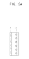
- FIG. 2A is a side view showing a structure of a backlight of a conventional liquid crystal display (LCD) apparatus.
- FIG. 2B is a front view showing a structure of a backlight of a conventional LCD apparatus.
- LCD liquid crystal display
- an LCD apparatus with an LCD has a backlight 3 illuminating a display unit 1 on which video signals are displayed.
- an alternating-current (AC) power is applied to the backlight 3.
- the backlight 3 is implemented in the form of a cold cathode fluorescence lamp (CCFL) which is a kind of a cold cathode ray tube whose brightness is controlled according to the intensity of the AC power.
- the backlight 3 is arranged at a rear side of the display unit 1 and provides light so that the luminance level, according to the gray scale level of the input video signal, can be applied. Accordingly, the gray scale level of the input video signal and the light provided from the backlight are merged to thus determine the luminance level.
- the display apparatus is disused or is classified as a low-class display apparatus.
- a conventional display apparatus gamma-converts input video signals using one gamma characteristic curve. Therefore, when the conventional display apparatus has a problem that occurred in the manufacture of the display apparatus, even though a video signal having an identical gray scale level is input to the conventional display apparatus, such a conventional display apparatus has a problem of uneven luminance level on the display unit 1.
- the backlight 3 exhibits a difference in a degree of deterioration in different portions thereof, and a uniformity of the luminance level on the display unit 1 becomes worse as the time of using the backlight 3 elapses.
- a display apparatus and a control method thereof which enables a luminance level of a video signal to be uniformly applied in a case that the light is not provided uniformly to respective portions of a display unit in the display apparatus.
- Exemplary embodiments of the present invention overcome the above disadvantages and disadvantages not described above.
- the present invention is not required to overcome the problems described above, and an exemplary embodiment of the present invention may not overcome any of the problems described above.
- a display apparatus including a display unit, comprising: a signal input unit to which a video signal and a synchronization signal are input; a storage unit in which a luminance conversion table corresponding to a plurality of display regions divided on the display unit is stored; a signal processor for processing the video signal to display on the display unit; and a controller for controlling the signal processor converts the video signal so that a luminance level of the video signal is applied based on the luminance conversion table.
- the controller determines a display region on which the video signal is displayed based on the input synchronization signal, confirms the luminance conversion table corresponding to the determined display region from the storage unit, and controls the signal processor so that the luminance level of the video signal is applied based on the confirmed luminance conversion table.
- the luminance conversion table is set up based on the result from detecting the luminance level, which is applied in correspondence to a gray scale level of the input video signal, by the plurality of display regions, and comparing the detected luminance level with a predetermined reference luminance level.
- the luminance conversion table is set up based on a result of detecting luminance levels of a plurality of display regions, which are applied in accordance with a gray scale level of the video signal, and comparing the detected luminance levels with a reference luminance level.
- the reference luminance level is any one of a minimum luminance level and an average luminance level among the detected luminance levels by the display regions.
- the controller comprises a counter which counts the number of synchronization signals and the number of clock signals in the synchronization signal, and determines the display region in which the video signal is displayed according to a count value of the counter.
- the counter comprises a horizontal synchronization counter counting the number of the horizontal synchronization signals, and a clock counter counting the number of the clock signals in the horizontal synchronization signal
- the controller confirms an abscissa of a pixel in which the video signal is displayed according to the count value of the clock counter, and an ordinate of the pixel in which the video signal is displayed according to the count value of the horizontal synchronization counter, and determines the display region in which the pixel is included.
- the aspects of the present invention are achieved by providing a control method of controlling a display apparatus having a display unit, the control method comprising: inputting a video signal and a synchronization signal; and converting the video signal to have a luminance level of the determined display region based on a prestored luminance conversion table.
- converting the video signal comprises: determining a display region in which a video signal is displayed, based on an input synchronization signal if a video signal and the synchronization signal are input to the display apparatus; and converting the video signal in order to apply a luminance level of the determined display region based on a prestored luminance conversion table.
- control method further comprises setting and storing the luminance conversion table corresponding to a plurality of display regions divided on the display unit.
- the setting the luminance conversion table comprises: detecting the luminance level applied in correspondence to a gray scale level of the input video signal by a plurality of display regions; comparing the detected luminance level and a predetermined reference luminance level; and setting the luminance conversion table based on the comparison result of comparing the luminance level and the reference luminance level.
- the reference luminance level is any one of a minimum luminance level and an average luminance level among the detected luminance levels by the display regions.
- the determining the display region in which the video signal is displayed comprises determining the display region according to a count value obtained by counting the number of the synchronization signals and the number of clock signals in the synchronization signal.
- the determining the display region in which the video signal is displayed comprises: confirming an ordinate of a pixel in which the video signal is displayed, by the count value obtained by counting the number of horizontal synchronization signals; confirming an abscissa of the pixel in which the video signal is displayed, by the count value obtained by counting the number of clock signals in the horizontal synchronization signal; and determining the display region in which the pixel is included based on the ordinate and abscissa of the confirmed pixel.
- FIG. 1 FIG. 1A, FIG. 2B, FIG. 3, FIG. 4, FIG. 5A, FIG. 5B, FIG. 5C, FIG. 6 and FIG. 7.
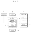
- FIG. 3 is a control block diagram of a display apparatus according to an exemplary embodiment of the present invention.
- a display apparatus includes a signal input unit 10, a signal processor 20, a display panel 30, a storage unit 40, and a controller 50.
- the signal input unit 10 receives a video signal and a synchronization signal, and may include a tuner (not shown) receiving a broadcast signal and an outer connector (not shown) receiving the video signal from an external device.
- the signal input unit 10 may include at least one of a D-Sub connector, a Composite Video Baseband Signal (CVBS) connector, S-video connector, and a component connector.
- CVBS Composite Video Baseband Signal
- the signal processor 20 processes the video signal input from the signal input unit 10, under the control of the controller 50 (which is described below), and provides the processed video signal so as to be displayed on a display unit 35. Particularly, the signal processor 20 converts a gray scale level of the video signal using a luminance conversion table.
- the signal processor 20 may include various functions in correspondence with the format of the input video signal.
- the signal processor 20 may include an analog to digital converting function for converting the input video signal of various analog formats into a digital video signal of a certain format, a digital decoding function, a scaling function for receiving a digital video signal and/or an analog video signal so as to control a vertical frequency, a resolution, an aspect ratio, etc., which correspond to an output specification of the display panel 30, and a predetermined format conversion function.
- the display panel 30 displays the processed video signal output from the signal processor 20, and includes the display unit 35, a backlight 33 and a driving unit 31.
- the display unit 35 displays the video signal and is divided into a plurality of display regions.
- the display unit 35 can be implemented in a variety of forms such as a Liquid Crystal Display (LCD) and a Plasma Display Panel (PDP), for example.
- LCD Liquid Crystal Display
- PDP Plasma Display Panel
- the backlight 33 illuminates the display unit 35, and generally includes a lamp as a light source, an optical sheet including a light guide plate, a prism sheet, a polarizer, etc., for converting the light emitted from the lamp into a surface light source and for enhancing light efficiency and luminance.
- a lamp as a light source
- an optical sheet including a light guide plate, a prism sheet, a polarizer, etc.
- the backlight 33 used for the display apparatus according to an exemplary embodiment of the present invention can be implemented by a cold cathode fluorescence lamp (CCFL), which is a kind of a cold cathode ray tube that receives electric power from an AC power supply, and whose brightness is controlled according to the intensity of the AC power.
- CCFL cold cathode fluorescence lamp
- the backlight 33 is arranged at the rear end of the display unit 35 and provides the light so that images are displayed on the display unit 35.
- the driving unit 31 receives electric power from an electric power supply (not shown), which supplies electric power and thus drives the backlight 33. That is, the driving unit 31 converts the DC electric power, which is supplied from the electric power supply (not shown), into AC electric power and then outputs the AC electric power necessary for driving the backlight 33. According to this exemplary embodiment of the present invention, the driving unit 31 controls the size of the driving current supplied to the backlight 33, under the control of the controller 50, to thereby control the backlight 33 to generate light.
- the storage unit 40 stores a luminance conversion table corresponding to a plurality of display regions displayed on the display unit 35, and can be implemented by an Electrically Erasable Programmable Read-Only Memory (EEPROM), an Erasable Programmable Read-Only Memory (EPROM), etc. Moreover, the storage unit 40 can be implemented by a frame buffer in which the video signal processed by the signal processor 20 is recorded in units of a frame.
- EEPROM Electrically Erasable Programmable Read-Only Memory
- EPROM Erasable Programmable Read-Only Memory
- the luminance conversion table can be set by the controller 50 (which is described below), and can be stored in a manufacturing process of the display apparatus. Moreover, if the display unit 35 is divided into display regions of M ⁇ N, the luminance conversion tables of M ⁇ N are stored in the storage unit 40 in correspondence with the display regions. The detailed description of the luminance conversion tables is described below.
- the controller 50 determines a display region in which the video signal is displayed based on the synchronization signal, and controls the video signal to be converted based on the luminance conversion tables corresponding to the determined display region.
- the controller 50 can be implemented by a controller including a central processing unit (CPU), a microcomputer (MICOM), etc.
- the controller 50 includes a counter 55, which counts the number of the synchronization signals and the number of the clock signals in the synchronization signal, and determines the display region in which the video signal is displayed, by using the counter 55.
- the counter 55 includes a horizontal synchronization counter 51, which counts the number of the horizontal synchronization signals, and a clock counter 53, which counts the number of the clock signals in the horizontal synchronization signal.
- the vertical synchronization signal is synchronized at the beginning time of every frame
- the horizontal synchronization signal is synchronized with the beginning time of every line in a frame.
- the clock signals are generated from the controller 50 using the horizontal synchronization signal, in order to process the video signal included in every line.
- the horizontal synchronization counter 51 counts the number of the horizontal synchronization signals and confirms an ordinate of the pixel in which the video signal processed in the signal processor 20 will be displayed, that is, a row number of the pixel.
- the clock counter 53 If the horizontal synchronization signal has been synchronized, a new line is initiated, and thus the clock counter 53 resets the count value to zero. Then, the clock counter 53 counts the number of the clock signals in the horizontal synchronization signal and confirms an abscissa of the pixel in which the video signal processed in the signal processor 20 will be displayed, that is, a column number of the pixel in the aforementioned row.
- the controller 50 judges where the video signal processed in the signal processor 20 is included among a plurality of display regions in the display unit 35, using the abscissa and the ordinate of the pixel confirmed by the counter 55.
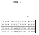
- FIG. 4 is a view showing a display unit, which is divided into sixteen display regions according to an exemplary embodiment of the present invention. As shown in FIG. 4, if the display unit 35 is divided into the display regions of 4 ⁇ 4, the display regions are classified into sixteen regions from the first region to the sixteenth region, respectively.
- one display region includes 256 ⁇ 192 pixels.
- the controller 50 can judge that the video signal which is being processed in the signal processor 20 is included in the tenth region among the sixteen divided display regions.
- the controller 50 confirms a luminance conversion table corresponding to the determined display region from the storage unit 40, and controls the signal processor 20 so that the luminance level of the video signal is applied based on the corresponding confirmed luminance conversion table, which is stored in the storage unit 40.
- the controller 50 should control the luminance level to be applied as 80cd according to the luminance conversion table. Therefore, the controller 50 controls the signal processor 20 to convert the gray scale level of the currently processed video signal into a level 1.
- the controller 50 detects the luminance level which is applied in correspondence to the gray scale level of the input video signal by a plurality of display regions, and sets the luminance conversion table based on the result comparing the detected luminance level and a predetermined reference luminance level to then be stored in the storage unit 40.
- the luminance conversion table is a table or a function regarding luminance levels which are applied according to the gray scale level of the input video signal, and is set in a manufacturing process of the display apparatus to then be stored in the storage unit 40.
- the controller 50 controls the display unit 35, which is divided into a plurality of display regions, to make the gray scale level of the video signal by the display regions from the minimum level, for example, zero to the maximum level, for example, 255.
- the controller 50 also detects the luminance level which is applied accordingly.
- the luminance level can be detected by a luminance detector (not shown).
- the controller 50 receives the luminance level detected by the luminance detector and sets the luminance conversion table.
- the controller 50 controls the driving unit 31 to supply identical drive electric power to the backlight 33 in each of a plurality of display regions at the detection time of the luminance level, so that the brightness of the light generated from the backlight 33 is identical. This is because the luminance level may be changed on every display region of the display apparatus, if the brightness of the light emitted from the backlight 33 is changed, even though the gray scale levels of the video signal and the magnitude of the driving power which the driving unit 31 provides to the backlight 33 remain constant.
- the controller 50 sets a minimum luminance level or an average luminance level, among the detected luminance levels by display region, as a reference luminance level. And, the controller 50 may set the luminance conversion table based on a result from a comparison of the detected luminance level with a predetermined reference luminance level to then be stored in the storage unit 40.
- the controller 50 can set any one of the minimum luminance levels having the minimum value among the detected luminance levels, and the average luminance level, which is an average value of the detected display region luminance levels, as the predetermined reference luminance level under the condition that the gray scale levels of the video signals input to the display regions are identical, to thereby set the luminance conversion table.
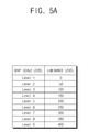
- FIG. 5A shows a table depicting a luminance level detected according to a gray scale level of a video signal input to a first region according to an exemplary embodiment of the present invention.
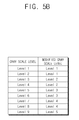
- FIG. 5B is a view showing a luminance conversion table of a first region according to an exemplary embodiment of the present invention.
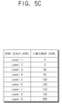
- FIG. 5C is a view showing a luminance level which is applied by converting the video signal input to the first region according to an exemplary embodiment using the luminance conversion table.
- the minimum gray scale level of the video signal is a level 0
- the maximum gray scale level is a level 9.
- the luminance level is 0cd
- the luminance level is 400cd.
- the reference luminance level is 200cd
- the luminance level should be applied as 200cd according to the luminance conversion table shown in FIG. 5B.
- the luminance conversion table can be produced as illustrated in FIG. 5B.
- the gray scale level when the input gray scale level is a level 1, the luminance level is 0cd, and when the input gray scale level is a level 2, the gray scale level is converted into a level 1 so that the luminance level becomes 0cd.
- the luminance level has been applied as 50cd before the luminance level is converted according to the luminance conversion table.
- the luminance level is converted according to the luminance conversion table shown in FIG. 5B, then, as shown in FIG. 5C, the luminance level is applied as 0cd.
- the gray scale level of the video signal is converted into a level 5 so that the luminance level should be applied as 200cd, and the maximum luminance level of 400cd detected from the first region is reduced to the reference luminance level of 200cd according to the luminance conversion table.
- the display unit 35 is provided with a plural luminance conversion tables corresponding to each display region. Accordingly, if the gray scale levels of the input video signals are identical to each other, the adjusted luminance levels will be uniformly applied for the same gray scale levels of the input video signals.
- the screen quality can be improved by improving a luminance on every display region.
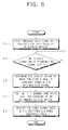
- the luminance conversion tables corresponding to the plurality of display regions are set and stored in a display unit 35 (operation S11).
- a controller 50 determines the display region in which the video signal will be displayed based on the synchronization signal (operation S15). As described above, for example, the controller 50 can determine the display region in which the video signal will be displayed according to the count value which counts the number of the synchronization signals and the number of the clock signals in the synchronization signal using a counter 55.
- the signal processor 20 is controlled to convert the video signal based on the confirmed luminance conversion table (operation S19). As described above, for instance, the signal processor 20 converts the gray scale level of the video signal so that the luminance levels are uniformly applied according to the display regions.
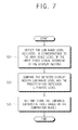
- the gray scale level of the video signal is converted from the minimum gray scale level to the maximum gray scale level.
- the indicated luminance level is detected according to the display regions (operation S21).
- the controller 50 controls the driving unit 31 so that the light intensity radiating from the backlight 33 is uniform.
- the indicated luminance level is measured.
- the luminance conversion table is then set based on the comparison result and is stored in the storage 40 unit (operation S25).
- the luminance conversion tables are set in a manufacturing process of the display apparatus, and such luminance conversion tables can be put on the market.
- the luminance non-uniformity which can occur due to a problem of the display apparatus itself can be supplemented by converting the video signal. Further, since a luminance level is uniformly applied on every display region, the product value can be prevented from falling.
- exemplary embodiments of the present invention can prevent the luminance non-uniformity caused by the difference in deterioration rates by the display regions as the use time elapses. Additionally, in a case requiring uniformity on the full screen, the error of determination from the error of the apparatus can be prevented.
Landscapes
- Engineering & Computer Science (AREA)
- Physics & Mathematics (AREA)
- General Physics & Mathematics (AREA)
- Computer Hardware Design (AREA)
- Theoretical Computer Science (AREA)
- Nonlinear Science (AREA)
- Signal Processing (AREA)
- Multimedia (AREA)
- Chemical & Material Sciences (AREA)
- Optics & Photonics (AREA)
- Crystallography & Structural Chemistry (AREA)
- Mathematical Physics (AREA)
- Control Of Indicators Other Than Cathode Ray Tubes (AREA)
- Control Of El Displays (AREA)
- Transforming Electric Information Into Light Information (AREA)
Applications Claiming Priority (1)
| Application Number | Priority Date | Filing Date | Title |
|---|---|---|---|
| KR1020060052423A KR20070118371A (ko) | 2006-06-12 | 2006-06-12 | 디스플레이장치 및 그 제어방법 |
Publications (2)
| Publication Number | Publication Date |
|---|---|
| EP1868178A2 true EP1868178A2 (fr) | 2007-12-19 |
| EP1868178A3 EP1868178A3 (fr) | 2008-07-30 |
Family
ID=38474006
Family Applications (1)
| Application Number | Title | Priority Date | Filing Date |
|---|---|---|---|
| EP07108617A Withdrawn EP1868178A3 (fr) | 2006-06-12 | 2007-05-22 | Appareil d'affichage et son procédé de commande |
Country Status (4)
| Country | Link |
|---|---|
| US (1) | US20070285380A1 (fr) |
| EP (1) | EP1868178A3 (fr) |
| KR (1) | KR20070118371A (fr) |
| CN (1) | CN101089941A (fr) |
Families Citing this family (18)
| Publication number | Priority date | Publication date | Assignee | Title |
|---|---|---|---|---|
| KR101336977B1 (ko) * | 2006-11-11 | 2013-12-06 | 삼성디스플레이 주식회사 | 액정 표시 장치 및 이의 구동 방법 |
| TWI400692B (zh) * | 2008-08-05 | 2013-07-01 | Chunghwa Picture Tubes Ltd | 液晶顯示器及其影像資料處理裝置與方法 |
| CN101727843B (zh) * | 2008-10-10 | 2011-12-28 | 华映视讯(吴江)有限公司 | 液晶显示器及其影像数据处理装置与方法 |
| CN101751880B (zh) * | 2008-12-03 | 2012-11-21 | 群康科技(深圳)有限公司 | 液晶显示装置及其图像补偿方法 |
| KR100959284B1 (ko) | 2009-05-08 | 2010-05-26 | 삼성전자주식회사 | 디스플레이 구동소자가 하부에 배치된 디스플레이 장치 |
| US20110122323A1 (en) * | 2009-11-26 | 2011-05-26 | Samsung Electronics Co., Ltd. | Flat cable and display apparatus including the same |
| CN101937653A (zh) * | 2010-09-27 | 2011-01-05 | 彩虹集团公司 | 一种分区亮度一致性调整方法 |
| KR101717565B1 (ko) * | 2010-12-23 | 2017-03-17 | 삼성전자 주식회사 | 디스플레이장치 및 그 제어방법 |
| TWI444962B (zh) * | 2011-12-15 | 2014-07-11 | Au Optronics Corp | 具光學補償功能之顯示裝置及其補償方法 |
| CN103051777A (zh) * | 2012-12-04 | 2013-04-17 | 北京百度网讯科技有限公司 | 移动终端屏幕亮度的控制方法、装置和移动终端 |
| CN103500566B (zh) * | 2013-09-29 | 2016-10-05 | 京东方科技集团股份有限公司 | 显示设备、显示亮度不均改善装置及改善方法 |
| CN104010129A (zh) * | 2014-04-23 | 2014-08-27 | 小米科技有限责任公司 | 图像处理方法、装置及终端 |
| CN105280149B (zh) * | 2015-11-11 | 2017-11-17 | 深圳市华星光电技术有限公司 | 一种Mura补偿数据写入装置及方法 |
| JP7054577B2 (ja) * | 2017-11-20 | 2022-04-14 | シナプティクス インコーポレイテッド | 表示ドライバ、表示装置及びムラ補正方法 |
| CN109559696B (zh) * | 2018-12-24 | 2021-08-24 | 惠科股份有限公司 | 显示模组及其伽马电压调节方法,以及显示装置 |
| CN112825232B (zh) * | 2019-11-20 | 2023-01-06 | 华为技术有限公司 | 一种补偿方法及电子设备 |
| US20220114959A1 (en) * | 2020-05-24 | 2022-04-14 | Sitronix Technology Corp. | Driving circuit for display panel |
| CN115299909A (zh) * | 2022-08-01 | 2022-11-08 | 华南理工大学 | 一种采用硬件实现的ppg波形及心率探测系统 |
Family Cites Families (6)
| Publication number | Priority date | Publication date | Assignee | Title |
|---|---|---|---|---|
| DE69022891T2 (de) * | 1989-06-15 | 1996-05-15 | Matsushita Electric Ind Co Ltd | Gerät zur Kompensierung von Videosignalen. |
| CN1070013C (zh) * | 1994-12-14 | 2001-08-22 | 松下电器产业株式会社 | 具有校正亮度不均匀性的电路的投影型图像显示装置 |
| JP3659065B2 (ja) * | 1999-01-29 | 2005-06-15 | 松下電器産業株式会社 | 画像表示装置 |
| JP2001209358A (ja) * | 2000-01-26 | 2001-08-03 | Seiko Epson Corp | 表示画像のムラ補正 |
| US7129920B2 (en) * | 2002-05-17 | 2006-10-31 | Elcos Mircrodisplay Technology, Inc. | Method and apparatus for reducing the visual effects of nonuniformities in display systems |
| US6989636B2 (en) * | 2004-06-16 | 2006-01-24 | Eastman Kodak Company | Method and apparatus for uniformity and brightness correction in an OLED display |
-
2006
- 2006-06-12 KR KR1020060052423A patent/KR20070118371A/ko not_active Withdrawn
-
2007
- 2007-05-22 EP EP07108617A patent/EP1868178A3/fr not_active Withdrawn
- 2007-06-07 US US11/759,495 patent/US20070285380A1/en not_active Abandoned
- 2007-06-08 CN CNA2007101103151A patent/CN101089941A/zh active Pending
Also Published As
| Publication number | Publication date |
|---|---|
| CN101089941A (zh) | 2007-12-19 |
| EP1868178A3 (fr) | 2008-07-30 |
| US20070285380A1 (en) | 2007-12-13 |
| KR20070118371A (ko) | 2007-12-17 |
Similar Documents
| Publication | Publication Date | Title |
|---|---|---|
| EP1868178A2 (fr) | Appareil d'affichage et son procédé de commande | |
| US7202458B2 (en) | Display and control method thereof | |
| TW527497B (en) | Liquid crystal display with a function of adaptive brightness intensifier and method for driving thereof | |
| JP4011104B2 (ja) | 液晶表示装置 | |
| CN102262866B (zh) | 液晶显示装置 | |
| EP1705636B1 (fr) | Appareil et procédé d'affichage | |
| US20090244112A1 (en) | Display apparatus and method thereof | |
| US8368724B2 (en) | Display apparatus and control method thereof for saving power | |
| US20100328336A1 (en) | Liquid Crystal Display Wall and Method for Controlling the Same | |
| US20090066632A1 (en) | Processing device and processing method for high dynamic constrast of liquid crystal display device | |
| CN101794542A (zh) | 图像显示装置 | |
| CN101371291A (zh) | 液晶显示装置 | |
| EP1945016A2 (fr) | Appareil d'affichage, unité de ventilateur et son procédé de contrôle de la vitesse | |
| CN102237064A (zh) | 液晶显示装置和背光源的控制方法 | |
| KR20090040673A (ko) | 액정표시기기의 화질 개선 장치 및 방법 | |
| US8054383B2 (en) | Display apparatus and method of preventing image burn-in | |
| EP1796441A2 (fr) | Appareil d'affichage d'images et procédé de contrôle de puissance de l'appareil d'affichage d'images | |
| TWI427615B (zh) | 具有自動調整亮度的顯示裝置與其操作方法 | |
| US8368685B2 (en) | Image display apparatus | |
| KR20070068795A (ko) | 디스플레이장치 및 그 제어방법 | |
| JP2008042843A (ja) | 液晶パネルの画面の輝度ムラの補正 | |
| US20060103644A1 (en) | Display apparatus and method for eliminating incidental image thereof | |
| KR100523598B1 (ko) | 액정 표시 장치용 백 라이트의 휘도 조절 방법 및 저전력모드 구현 방법 | |
| WO2008030056A1 (fr) | Appareil et procédé destinés à commander la luminance d'un dispositif d'affichage | |
| CN101010654B (zh) | 显示装置及其控制方法 |
Legal Events
| Date | Code | Title | Description |
|---|---|---|---|
| PUAI | Public reference made under article 153(3) epc to a published international application that has entered the european phase |
Free format text: ORIGINAL CODE: 0009012 |
|
| AK | Designated contracting states |
Kind code of ref document: A2 Designated state(s): AT BE BG CH CY CZ DE DK EE ES FI FR GB GR HU IE IS IT LI LT LU LV MC MT NL PL PT RO SE SI SK TR |
|
| AX | Request for extension of the european patent |
Extension state: AL BA HR MK YU |
|
| PUAL | Search report despatched |
Free format text: ORIGINAL CODE: 0009013 |
|
| AK | Designated contracting states |
Kind code of ref document: A3 Designated state(s): AT BE BG CH CY CZ DE DK EE ES FI FR GB GR HU IE IS IT LI LT LU LV MC MT NL PL PT RO SE SI SK TR |
|
| AX | Request for extension of the european patent |
Extension state: AL BA HR MK RS |
|
| RIC1 | Information provided on ipc code assigned before grant |
Ipc: G09G 3/20 20060101AFI20080620BHEP |
|
| AKX | Designation fees paid | ||
| REG | Reference to a national code |
Ref country code: DE Ref legal event code: 8566 |
|
| STAA | Information on the status of an ep patent application or granted ep patent |
Free format text: STATUS: THE APPLICATION IS DEEMED TO BE WITHDRAWN |
|
| 18D | Application deemed to be withdrawn |
Effective date: 20090131 |