EP1868213A1 - Matiere magnetique tendre et procede de production de comprime en cru - Google Patents
Matiere magnetique tendre et procede de production de comprime en cru Download PDFInfo
- Publication number
- EP1868213A1 EP1868213A1 EP05727280A EP05727280A EP1868213A1 EP 1868213 A1 EP1868213 A1 EP 1868213A1 EP 05727280 A EP05727280 A EP 05727280A EP 05727280 A EP05727280 A EP 05727280A EP 1868213 A1 EP1868213 A1 EP 1868213A1
- Authority
- EP
- European Patent Office
- Prior art keywords
- iron particles
- iron
- particles
- soft magnetic
- magnetic material
- Prior art date
- Legal status (The legal status is an assumption and is not a legal conclusion. Google has not performed a legal analysis and makes no representation as to the accuracy of the status listed.)
- Withdrawn
Links
- 239000000696 magnetic material Substances 0.000 title claims abstract description 34
- 238000000034 method Methods 0.000 title claims description 71
- 230000008569 process Effects 0.000 title description 29
- XEEYBQQBJWHFJM-UHFFFAOYSA-N Iron Chemical compound [Fe] XEEYBQQBJWHFJM-UHFFFAOYSA-N 0.000 claims abstract description 293
- 239000002245 particle Substances 0.000 claims abstract description 150
- 229910052742 iron Inorganic materials 0.000 claims abstract description 139
- 239000000843 powder Substances 0.000 claims abstract description 71
- 239000005416 organic matter Substances 0.000 claims description 40
- 239000000314 lubricant Substances 0.000 claims description 23
- 229920005992 thermoplastic resin Polymers 0.000 claims description 8
- 238000010438 heat treatment Methods 0.000 claims description 5
- 235000014113 dietary fatty acids Nutrition 0.000 claims description 4
- 239000000194 fatty acid Substances 0.000 claims description 4
- 229930195729 fatty acid Natural products 0.000 claims description 4
- 150000004665 fatty acids Chemical class 0.000 claims description 4
- 238000007561 laser diffraction method Methods 0.000 claims description 4
- 238000000790 scattering method Methods 0.000 claims description 4
- 238000001179 sorption measurement Methods 0.000 claims description 4
- 238000004438 BET method Methods 0.000 claims description 2
- 229910000398 iron phosphate Inorganic materials 0.000 description 30
- WBJZTOZJJYAKHQ-UHFFFAOYSA-K iron(3+) phosphate Chemical compound [Fe+3].[O-]P([O-])([O-])=O WBJZTOZJJYAKHQ-UHFFFAOYSA-K 0.000 description 30
- 239000002131 composite material Substances 0.000 description 20
- 239000006249 magnetic particle Substances 0.000 description 20
- VYPSYNLAJGMNEJ-UHFFFAOYSA-N Silicium dioxide Chemical compound O=[Si]=O VYPSYNLAJGMNEJ-UHFFFAOYSA-N 0.000 description 19
- -1 polyethylene Polymers 0.000 description 19
- 239000004698 Polyethylene Substances 0.000 description 18
- 239000000428 dust Substances 0.000 description 18
- 229920000573 polyethylene Polymers 0.000 description 18
- 239000010410 layer Substances 0.000 description 14
- ILRRQNADMUWWFW-UHFFFAOYSA-K aluminium phosphate Chemical compound O1[Al]2OP1(=O)O2 ILRRQNADMUWWFW-UHFFFAOYSA-K 0.000 description 11
- 238000004519 manufacturing process Methods 0.000 description 11
- 239000000463 material Substances 0.000 description 11
- 229920005989 resin Polymers 0.000 description 11
- 239000011347 resin Substances 0.000 description 11
- 239000007789 gas Substances 0.000 description 10
- 239000000203 mixture Substances 0.000 description 10
- XOOUIPVCVHRTMJ-UHFFFAOYSA-L zinc stearate Chemical compound [Zn+2].CCCCCCCCCCCCCCCCCC([O-])=O.CCCCCCCCCCCCCCCCCC([O-])=O XOOUIPVCVHRTMJ-UHFFFAOYSA-L 0.000 description 10
- 239000000377 silicon dioxide Substances 0.000 description 9
- 238000012360 testing method Methods 0.000 description 7
- 230000000694 effects Effects 0.000 description 6
- 239000007788 liquid Substances 0.000 description 6
- XLYOFNOQVPJJNP-UHFFFAOYSA-N water Substances O XLYOFNOQVPJJNP-UHFFFAOYSA-N 0.000 description 6
- 239000004677 Nylon Substances 0.000 description 5
- 229920001778 nylon Polymers 0.000 description 5
- 239000007921 spray Substances 0.000 description 5
- 230000006378 damage Effects 0.000 description 4
- 230000001788 irregular Effects 0.000 description 4
- 230000003746 surface roughness Effects 0.000 description 4
- 229920006259 thermoplastic polyimide Polymers 0.000 description 4
- IJGRMHOSHXDMSA-UHFFFAOYSA-N Atomic nitrogen Chemical compound N#N IJGRMHOSHXDMSA-UHFFFAOYSA-N 0.000 description 3
- 239000004734 Polyphenylene sulfide Substances 0.000 description 3
- 238000010586 diagram Methods 0.000 description 3
- 230000004907 flux Effects 0.000 description 3
- 230000006698 induction Effects 0.000 description 3
- 238000000691 measurement method Methods 0.000 description 3
- 229910052751 metal Inorganic materials 0.000 description 3
- 239000002184 metal Substances 0.000 description 3
- 238000002156 mixing Methods 0.000 description 3
- 229920000069 polyphenylene sulfide Polymers 0.000 description 3
- 230000009467 reduction Effects 0.000 description 3
- 229920006395 saturated elastomer Polymers 0.000 description 3
- 229920006345 thermoplastic polyamide Polymers 0.000 description 3
- 239000004705 High-molecular-weight polyethylene Substances 0.000 description 2
- UFHFLCQGNIYNRP-UHFFFAOYSA-N Hydrogen Chemical compound [H][H] UFHFLCQGNIYNRP-UHFFFAOYSA-N 0.000 description 2
- NBIIXXVUZAFLBC-UHFFFAOYSA-N Phosphoric acid Chemical compound OP(O)(O)=O NBIIXXVUZAFLBC-UHFFFAOYSA-N 0.000 description 2
- 239000004962 Polyamide-imide Substances 0.000 description 2
- PNEYBMLMFCGWSK-UHFFFAOYSA-N aluminium oxide Inorganic materials [O-2].[O-2].[O-2].[Al+3].[Al+3] PNEYBMLMFCGWSK-UHFFFAOYSA-N 0.000 description 2
- 125000003118 aryl group Chemical group 0.000 description 2
- 238000000498 ball milling Methods 0.000 description 2
- 238000005229 chemical vapour deposition Methods 0.000 description 2
- 239000011248 coating agent Substances 0.000 description 2
- 238000000576 coating method Methods 0.000 description 2
- 230000000052 comparative effect Effects 0.000 description 2
- 230000003247 decreasing effect Effects 0.000 description 2
- 238000009826 distribution Methods 0.000 description 2
- 238000002149 energy-dispersive X-ray emission spectroscopy Methods 0.000 description 2
- 239000003623 enhancer Substances 0.000 description 2
- 230000009477 glass transition Effects 0.000 description 2
- BHEPBYXIRTUNPN-UHFFFAOYSA-N hydridophosphorus(.) (triplet) Chemical compound [PH] BHEPBYXIRTUNPN-UHFFFAOYSA-N 0.000 description 2
- 239000001257 hydrogen Substances 0.000 description 2
- 229910052739 hydrogen Inorganic materials 0.000 description 2
- 238000007373 indentation Methods 0.000 description 2
- 238000001095 inductively coupled plasma mass spectrometry Methods 0.000 description 2
- 239000011261 inert gas Substances 0.000 description 2
- 229910052743 krypton Inorganic materials 0.000 description 2
- DNNSSWSSYDEUBZ-UHFFFAOYSA-N krypton atom Chemical compound [Kr] DNNSSWSSYDEUBZ-UHFFFAOYSA-N 0.000 description 2
- HGPXWXLYXNVULB-UHFFFAOYSA-M lithium stearate Chemical compound [Li+].CCCCCCCCCCCCCCCCCC([O-])=O HGPXWXLYXNVULB-UHFFFAOYSA-M 0.000 description 2
- HQKMJHAJHXVSDF-UHFFFAOYSA-L magnesium stearate Chemical compound [Mg+2].CCCCCCCCCCCCCCCCCC([O-])=O.CCCCCCCCCCCCCCCCCC([O-])=O HQKMJHAJHXVSDF-UHFFFAOYSA-L 0.000 description 2
- 238000005240 physical vapour deposition Methods 0.000 description 2
- 229920003023 plastic Polymers 0.000 description 2
- 239000004033 plastic Substances 0.000 description 2
- 229920002312 polyamide-imide Polymers 0.000 description 2
- 238000005245 sintering Methods 0.000 description 2
- 238000005979 thermal decomposition reaction Methods 0.000 description 2
- 238000011282 treatment Methods 0.000 description 2
- OKTJSMMVPCPJKN-UHFFFAOYSA-N Carbon Chemical compound [C] OKTJSMMVPCPJKN-UHFFFAOYSA-N 0.000 description 1
- PWHULOQIROXLJO-UHFFFAOYSA-N Manganese Chemical compound [Mn] PWHULOQIROXLJO-UHFFFAOYSA-N 0.000 description 1
- 229910019142 PO4 Inorganic materials 0.000 description 1
- 239000004696 Poly ether ether ketone Substances 0.000 description 1
- 239000004952 Polyamide Substances 0.000 description 1
- 239000004695 Polyether sulfone Substances 0.000 description 1
- 239000004697 Polyetherimide Substances 0.000 description 1
- 239000004642 Polyimide Substances 0.000 description 1
- 239000004743 Polypropylene Substances 0.000 description 1
- 229910000831 Steel Inorganic materials 0.000 description 1
- 238000003917 TEM image Methods 0.000 description 1
- GWEVSGVZZGPLCZ-UHFFFAOYSA-N Titan oxide Chemical compound O=[Ti]=O GWEVSGVZZGPLCZ-UHFFFAOYSA-N 0.000 description 1
- 229910000147 aluminium phosphate Inorganic materials 0.000 description 1
- 150000001408 amides Chemical class 0.000 description 1
- 238000004458 analytical method Methods 0.000 description 1
- 238000013459 approach Methods 0.000 description 1
- QVGXLLKOCUKJST-UHFFFAOYSA-N atomic oxygen Chemical compound [O] QVGXLLKOCUKJST-UHFFFAOYSA-N 0.000 description 1
- 230000005540 biological transmission Effects 0.000 description 1
- 230000015572 biosynthetic process Effects 0.000 description 1
- 239000001506 calcium phosphate Substances 0.000 description 1
- 229910000389 calcium phosphate Inorganic materials 0.000 description 1
- 235000011010 calcium phosphates Nutrition 0.000 description 1
- CJZGTCYPCWQAJB-UHFFFAOYSA-L calcium stearate Chemical compound [Ca+2].CCCCCCCCCCCCCCCCCC([O-])=O.CCCCCCCCCCCCCCCCCC([O-])=O CJZGTCYPCWQAJB-UHFFFAOYSA-L 0.000 description 1
- 235000013539 calcium stearate Nutrition 0.000 description 1
- 239000008116 calcium stearate Substances 0.000 description 1
- HRBZRZSCMANEHQ-UHFFFAOYSA-L calcium;hexadecanoate Chemical compound [Ca+2].CCCCCCCCCCCCCCCC([O-])=O.CCCCCCCCCCCCCCCC([O-])=O HRBZRZSCMANEHQ-UHFFFAOYSA-L 0.000 description 1
- ZCZLQYAECBEUBH-UHFFFAOYSA-L calcium;octadec-9-enoate Chemical compound [Ca+2].CCCCCCCCC=CCCCCCCCC([O-])=O.CCCCCCCCC=CCCCCCCCC([O-])=O ZCZLQYAECBEUBH-UHFFFAOYSA-L 0.000 description 1
- 238000004364 calculation method Methods 0.000 description 1
- 229910052799 carbon Inorganic materials 0.000 description 1
- 238000006243 chemical reaction Methods 0.000 description 1
- 238000000975 co-precipitation Methods 0.000 description 1
- 239000000571 coke Substances 0.000 description 1
- 150000001875 compounds Chemical class 0.000 description 1
- 238000001816 cooling Methods 0.000 description 1
- 230000008878 coupling Effects 0.000 description 1
- 238000010168 coupling process Methods 0.000 description 1
- 238000005859 coupling reaction Methods 0.000 description 1
- 238000005520 cutting process Methods 0.000 description 1
- 230000006866 deterioration Effects 0.000 description 1
- 229910001873 dinitrogen Inorganic materials 0.000 description 1
- 239000006185 dispersion Substances 0.000 description 1
- 238000001125 extrusion Methods 0.000 description 1
- 230000002349 favourable effect Effects 0.000 description 1
- 238000007542 hardness measurement Methods 0.000 description 1
- CPSYWNLKRDURMG-UHFFFAOYSA-L hydron;manganese(2+);phosphate Chemical compound [Mn+2].OP([O-])([O-])=O CPSYWNLKRDURMG-UHFFFAOYSA-L 0.000 description 1
- 239000012212 insulator Substances 0.000 description 1
- 238000011835 investigation Methods 0.000 description 1
- AVOVSJYQRZMDQJ-KVVVOXFISA-M lithium;(z)-octadec-9-enoate Chemical compound [Li+].CCCCCCCC\C=C/CCCCCCCC([O-])=O AVOVSJYQRZMDQJ-KVVVOXFISA-M 0.000 description 1
- BZMIKKVSCNHEFL-UHFFFAOYSA-M lithium;hexadecanoate Chemical compound [Li+].CCCCCCCCCCCCCCCC([O-])=O BZMIKKVSCNHEFL-UHFFFAOYSA-M 0.000 description 1
- 235000019359 magnesium stearate Nutrition 0.000 description 1
- 239000006247 magnetic powder Substances 0.000 description 1
- 229910052748 manganese Inorganic materials 0.000 description 1
- 239000011572 manganese Substances 0.000 description 1
- 238000005259 measurement Methods 0.000 description 1
- 238000005551 mechanical alloying Methods 0.000 description 1
- 238000012986 modification Methods 0.000 description 1
- 230000004048 modification Effects 0.000 description 1
- 229910052757 nitrogen Inorganic materials 0.000 description 1
- TWNQGVIAIRXVLR-UHFFFAOYSA-N oxo(oxoalumanyloxy)alumane Chemical compound O=[Al]O[Al]=O TWNQGVIAIRXVLR-UHFFFAOYSA-N 0.000 description 1
- 239000001301 oxygen Substances 0.000 description 1
- 229910052760 oxygen Inorganic materials 0.000 description 1
- RVTZCBVAJQQJTK-UHFFFAOYSA-N oxygen(2-);zirconium(4+) Chemical compound [O-2].[O-2].[Zr+4] RVTZCBVAJQQJTK-UHFFFAOYSA-N 0.000 description 1
- 239000010452 phosphate Substances 0.000 description 1
- NBIIXXVUZAFLBC-UHFFFAOYSA-K phosphate Chemical compound [O-]P([O-])([O-])=O NBIIXXVUZAFLBC-UHFFFAOYSA-K 0.000 description 1
- 238000007747 plating Methods 0.000 description 1
- 229920000058 polyacrylate Polymers 0.000 description 1
- 229920002647 polyamide Polymers 0.000 description 1
- 229920000728 polyester Polymers 0.000 description 1
- 229920006393 polyether sulfone Polymers 0.000 description 1
- 229920002530 polyetherether ketone Polymers 0.000 description 1
- 229920001601 polyetherimide Polymers 0.000 description 1
- 229920001721 polyimide Polymers 0.000 description 1
- 229920000193 polymethacrylate Polymers 0.000 description 1
- 229920001155 polypropylene Polymers 0.000 description 1
- 238000012545 processing Methods 0.000 description 1
- 238000010298 pulverizing process Methods 0.000 description 1
- 229910052814 silicon oxide Inorganic materials 0.000 description 1
- 239000002356 single layer Substances 0.000 description 1
- 239000000344 soap Substances 0.000 description 1
- 238000003980 solgel method Methods 0.000 description 1
- 238000005507 spraying Methods 0.000 description 1
- 238000004544 sputter deposition Methods 0.000 description 1
- 239000010959 steel Substances 0.000 description 1
- 238000010998 test method Methods 0.000 description 1
- 229920001169 thermoplastic Polymers 0.000 description 1
- 239000004416 thermosoftening plastic Substances 0.000 description 1
- OGIDPMRJRNCKJF-UHFFFAOYSA-N titanium oxide Inorganic materials [Ti]=O OGIDPMRJRNCKJF-UHFFFAOYSA-N 0.000 description 1
- QORWJWZARLRLPR-UHFFFAOYSA-H tricalcium bis(phosphate) Chemical compound [Ca+2].[Ca+2].[Ca+2].[O-]P([O-])([O-])=O.[O-]P([O-])([O-])=O QORWJWZARLRLPR-UHFFFAOYSA-H 0.000 description 1
- 238000005019 vapor deposition process Methods 0.000 description 1
- 230000000007 visual effect Effects 0.000 description 1
- 239000001993 wax Substances 0.000 description 1
- 238000005303 weighing Methods 0.000 description 1
- LRXTYHSAJDENHV-UHFFFAOYSA-H zinc phosphate Chemical compound [Zn+2].[Zn+2].[Zn+2].[O-]P([O-])([O-])=O.[O-]P([O-])([O-])=O LRXTYHSAJDENHV-UHFFFAOYSA-H 0.000 description 1
- 229910000165 zinc phosphate Inorganic materials 0.000 description 1
- 229910001928 zirconium oxide Inorganic materials 0.000 description 1
Images



Classifications
-
- H—ELECTRICITY
- H01—ELECTRIC ELEMENTS
- H01F—MAGNETS; INDUCTANCES; TRANSFORMERS; SELECTION OF MATERIALS FOR THEIR MAGNETIC PROPERTIES
- H01F41/00—Apparatus or processes specially adapted for manufacturing or assembling magnets, inductances or transformers; Apparatus or processes specially adapted for manufacturing materials characterised by their magnetic properties
- H01F41/02—Apparatus or processes specially adapted for manufacturing or assembling magnets, inductances or transformers; Apparatus or processes specially adapted for manufacturing materials characterised by their magnetic properties for manufacturing cores, coils, or magnets
- H01F41/0206—Manufacturing of magnetic cores by mechanical means
- H01F41/0246—Manufacturing of magnetic circuits by moulding or by pressing powder
-
- B—PERFORMING OPERATIONS; TRANSPORTING
- B22—CASTING; POWDER METALLURGY
- B22F—WORKING METALLIC POWDER; MANUFACTURE OF ARTICLES FROM METALLIC POWDER; MAKING METALLIC POWDER; APPARATUS OR DEVICES SPECIALLY ADAPTED FOR METALLIC POWDER
- B22F1/00—Metallic powder; Treatment of metallic powder, e.g. to facilitate working or to improve properties
- B22F1/10—Metallic powder containing lubricating or binding agents; Metallic powder containing organic material
-
- H—ELECTRICITY
- H01—ELECTRIC ELEMENTS
- H01F—MAGNETS; INDUCTANCES; TRANSFORMERS; SELECTION OF MATERIALS FOR THEIR MAGNETIC PROPERTIES
- H01F1/00—Magnets or magnetic bodies characterised by the magnetic materials therefor; Selection of materials for their magnetic properties
- H01F1/01—Magnets or magnetic bodies characterised by the magnetic materials therefor; Selection of materials for their magnetic properties of inorganic materials
- H01F1/03—Magnets or magnetic bodies characterised by the magnetic materials therefor; Selection of materials for their magnetic properties of inorganic materials characterised by their coercivity
- H01F1/12—Magnets or magnetic bodies characterised by the magnetic materials therefor; Selection of materials for their magnetic properties of inorganic materials characterised by their coercivity of soft-magnetic materials
- H01F1/14—Magnets or magnetic bodies characterised by the magnetic materials therefor; Selection of materials for their magnetic properties of inorganic materials characterised by their coercivity of soft-magnetic materials metals or alloys
- H01F1/20—Magnets or magnetic bodies characterised by the magnetic materials therefor; Selection of materials for their magnetic properties of inorganic materials characterised by their coercivity of soft-magnetic materials metals or alloys in the form of particles, e.g. powder
- H01F1/22—Magnets or magnetic bodies characterised by the magnetic materials therefor; Selection of materials for their magnetic properties of inorganic materials characterised by their coercivity of soft-magnetic materials metals or alloys in the form of particles, e.g. powder pressed, sintered, or bound together
- H01F1/24—Magnets or magnetic bodies characterised by the magnetic materials therefor; Selection of materials for their magnetic properties of inorganic materials characterised by their coercivity of soft-magnetic materials metals or alloys in the form of particles, e.g. powder pressed, sintered, or bound together the particles being insulated
-
- B—PERFORMING OPERATIONS; TRANSPORTING
- B22—CASTING; POWDER METALLURGY
- B22F—WORKING METALLIC POWDER; MANUFACTURE OF ARTICLES FROM METALLIC POWDER; MAKING METALLIC POWDER; APPARATUS OR DEVICES SPECIALLY ADAPTED FOR METALLIC POWDER
- B22F2998/00—Supplementary information concerning processes or compositions relating to powder metallurgy
-
- B—PERFORMING OPERATIONS; TRANSPORTING
- B22—CASTING; POWDER METALLURGY
- B22F—WORKING METALLIC POWDER; MANUFACTURE OF ARTICLES FROM METALLIC POWDER; MAKING METALLIC POWDER; APPARATUS OR DEVICES SPECIALLY ADAPTED FOR METALLIC POWDER
- B22F2998/00—Supplementary information concerning processes or compositions relating to powder metallurgy
- B22F2998/10—Processes characterised by the sequence of their steps
Definitions
- the present invention generally relates to a soft magnetic material and a method of producing a powder compact, and more particularly to a soft magnetic material containing a plurality of iron particles and a method of producing a powder compact.
- Patent Document 1 Japanese Unexamined Patent Application Publication No. 2002-246219
- iron particles purified by atomizing methods or reduction methods are used.
- atomizing methods an iron solution is sprayed using compressed gas or water, and then the resulting iron powder is subjected to pulverization, classification and other processes to produce iron particles.
- reduction methods iron ore and mill scale are reduced using coke, and then heated under a hydrogen atmosphere to produce iron particles. Therefore, iron particles purified using these methods would have been rapidly cooled in their production process. This causes severe strain or extreme stress to occur inside the iron particles, thereby increasing the hardness of the resulting iron particles. That is why iron particles having a Vickers hardness HV from about 800 to 1100 are used in actual production processes of the powder compact.
- the powder compact acquires integrity through entanglement of iron particles caused by their plastic deformation in the pressure-forming process.
- the integrity is relatively improved by formation of metal bonds between the particles and dispersion occurring in the sintering process, but in the powder compact (in particular, a dust core), the heating temperature used in the heating process is so low that sintering between the particles hardly occurs, and thus the strength of bonds between the particles is insufficient. Consequently, more complex entanglement of iron particles in the pressure-forming process is required for producing a powder compact with a high integrity
- the hardness of the iron particles used in production of a powder compact is high as described above.
- the high hardness makes plastic deformation of the iron particles in the pressure-forming process difficult to progress, thereby making the iron particles difficult to entangle. This results in insufficient integrity of the powder compact and thus raises several issues such as dropout of the iron particles from the surface of the powder compact and damage of the compact occurring in a cutting process and other processes.
- an object of the present invention is to solve the abovementioned problems and to provide a soft magnetic material used to produce a powder compact having a high integrity, and a method of producing such a powder compact.
- the soft magnetic material according to the present invention is a soft magnetic material used in production of a powder compact.
- This soft magnetic material contains a plurality of iron particles having a Vickers hardness HV of lower than 800. It should be noted that here the iron particles are particles containing iron at a purity from 95% to 100%.
- the iron particles have a Vickers hardness HV of lower than 800, and thus are easily plastically deformed in the pressure-forming process for producing a powder compact. This enables pressure-forming of the iron particles in such a manner that the particles are intricately entangled, thereby realizing a powder compact having a high integrity.
- the iron particles preferably satisfy the relationship of ⁇ / ⁇ ⁇ 2.5, where ⁇ represents the specific surface area of the iron particles measured by a gas adsorption method (Brunauer-Emmett-Teller (BET) method) and ⁇ represents the apparent specific surface area of the iron particles calculated from the average particle diameter measured by a laser diffraction/scattering method.
- BET Brunauer-Emmett-Teller
- ⁇ represents the apparent specific surface area of the iron particles calculated from the average particle diameter measured by a laser diffraction/scattering method.
- the ratio of the actual specific surface area ⁇ of the iron particles to the apparent specific surface area ⁇ is specified as 2.5 or higher, and thus the surface of the iron particles has large convex and concave portions.
- the iron particles are entangled more intricately in the pressure-forming process for producing a powder compact, and the integrity of the resulting powder compact is further improved.
- the iron particles have a Vickers hardness HV of 700 or lower and satisfy the relationship of ⁇ / ⁇ ⁇ 3.0. In the soft magnetic material in this configuration, the abovementioned effect would be enhanced.
- the soft magnetic material further contains insulating films covering the surface of the iron particles.
- the insulating films existing in gaps between adjacent iron particles significantly inhibit metal bonds between the iron particles processed into a powder compact.
- lubricity of the insulating films makes it impossible to couple the iron particles with each other intricately in the pressure-forming process for producing a powder compact. As a result, production of a powder compact having a high integrity becomes difficult.
- the present invention is thus suitably applied to the production process of such a soft magnetic material containing insulating films.
- the average thickness of the insulating films is preferably 5 nm to 100 nm.
- the tunnel current traveling in the films can be reduced as well as the gain in eddy current loss caused by this tunnel current can be reduced, because the average thickness of the insulating films is not less than 5 nm.
- the average thickness of the insulating films is not more than 100 nm, so that in the powder compact obtained using this soft magnetic material, the distance between the iron particles is sufficiently short. This can prevent generation of demagnetizing fields between the iron particles and thus can reduce the gain in hysteresis loss caused by the generation of those demagnetizing fields.
- the volume ratio of a nonmagnetic layer to the entire soft magnetic material can be reduced and loss in saturated magnetic flux density can be avoided.
- the method of producing a powder compact according to the present invention is a method of producing a powder compact using any one of the soft magnetic materials described above.
- the method of producing a powder compact includes a step wherein iron particles are put into a mold, and a step wherein the iron particles are pressurized to produce a powder compact.
- the iron particles are entangled intricately in the pressure-forming process for producing a powder compact, and the integrity of the resulting powder compact is improved.
- the step wherein iron particles are put into a mold preferably includes a step wherein the first organic matter containing thermoplastic resin and/or non-thermoplastic resin is added into the iron particles so that the content ratio of the first organic matter to the entire compact is 0.001 weight percent (wt%) to 0.2 wt%.
- the first organic matter is contained in the resulting powder compact so as to exist in gaps between the iron particles, thus coupling the iron particles with each other more firmly. This further improves the integrity of the obtained powder compact.
- the content ratio of the first organic matter of 0.001 wt% or more would be sufficient for obtaining the effect described above. Also, the content ratio of the first organic matter of 0.2 wt% or less would enable reducing the volume ratio of a nonmagnetic layer to the entire powder compact and thereby reduce the loss in saturated magnetic flux density.
- the step wherein iron particles are put into a mold preferably includes a step wherein the second organic matter containing a higher fatty acid-based lubricant is added into the iron particles so that the content ratio of the second organic matter to the entire compact is 0.001 wt% to 0.2 wt%.
- the second organic matter is contained in the resulting powder compact so as to exist in gaps between adjacent iron particles, thus avoiding significant friction between the iron particles. This reduces the gain of hysteresis loss in the powder compact by distorting the inside of each iron particle. In the case where the surface of each iron particles is covered by an insulating film, destruction of the insulating film during the pressure-forming process is also avoided. This can reduce the eddy current loss in the resulting powder compact.
- the content ratio of the second organic matter of 0.001 wt% or more would be sufficient for obtaining the effect described above.
- the content ratio of the second organic matter of 0.2 wt% or less would enable reducing the volume ratio of a nonmagnetic layer to the entire powder compact and thereby reduce the loss in saturated magnetic flux density.
- high lubricity of the second organic matter can prevent the powder compact from deterioration of the integrity.
- the step wherein iron particles are put into a mold includes a step wherein a lubricant is applied on the inner wall of the mold.
- a lubricant is applied on the inner wall of the mold.
- the step wherein iron particles are put into a mold includes a step wherein the inner wall of the mold and/or the iron particles are heated to a temperature of 40°C or higher.
- the strain inside the iron particles can be reduced as well as the hysteresis loss in the powder compact.
- the first organic matter contained in the iron particles is softened so as to fill gaps between the particles sufficiently. This can increase the density of the powder compact and further improve the integrity of the powder compact.
- the present invention provides a soft magnetic material used to produce a powder compact having a high integrity, and a method of producing such a powder compact.
- Figure 1 is a schematic diagram of the soft magnetic material in an embodiment of the present invention.
- the soft magnetic material contains iron particles 10 having a Vickers hardness HV of less than 800.
- the Vickers hardness HV of the iron particles 10 is preferably 700 or less.
- the Vickers hardness HV of the iron particles 10 is measured using a test method for micro Vickers hardness stipulated in Japanese Industrial Standards (JIS) Z2244, for example, using the following method. In this description, an aggregate of the iron particles 10 is called iron powder.
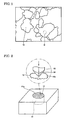
- the measurement method of the Vickers hardness HV of the iron particles shown in Fig. 1 is as follows. First, the iron powder is mixed with liquid resin or resin powder and then the mixture is heated (or undergoes a chemical reaction) until the resin is molten. After that, the molten resin is cured to produce resin 61 encapsulating the iron powder. Subsequently, the surface 61a of the resin 61 is subjected to lapping to form the planar section 10a, which is subjected to the hardness test, on the iron particles 10. A test pyramidal indenter 63 is pressed onto the planar section 10a with a test load of 0.5 N to form an indentation 64 in the surface of the iron particles 10. Then the diagonal length of the indentation 64 is measured for calculation of the Vickers hardness HV.
- the iron particles 10 satisfy the relationship of ⁇ / ⁇ ⁇ 2.5, where ⁇ represents the specific surface area of the iron particles 10 and ⁇ represents the apparent specific surface area of the iron particles 10.
- the iron particles further meet the relationship of ⁇ / ⁇ ⁇ 3.0.
- the specific surface area ⁇ and the apparent specific surface area ⁇ of the iron particles 10 can be determined according to the following method.
- the specific surface area ⁇ of the iron particles 10 is measured by a gas adsorption method (a measurement method of a specific surface area using the BET equation derived from the BET method). More specifically, a gas of molecules having a known size (such as nitrogen gas and krypton gas) is adsorbed by the surface of the iron particles 10, and the specific surface area ⁇ (m 2 /g) of the iron particles 10 is calculated from the amount of the adsorbed gas. In this method, the actual specific surface area ⁇ of the iron particles 10 can be determined by measuring the amount of the adsorbed gas over the surface of the iron particles 10.
- a gas adsorption method a measurement method of a specific surface area using the BET equation derived from the BET method. More specifically, a gas of molecules having a known size (such as nitrogen gas and krypton gas) is adsorbed by the surface of the iron particles 10, and the specific surface area ⁇ (m 2 /g) of the iron particles 10 is calculated from the amount of the adsorbed gas.
- the apparent specific surface area ⁇ of the iron particles 10 is calculated from the average particle diameter D of the iron particles 10 measured by a laser diffraction/scattering method.
- a sample weighing a few tens of grams is collected from the iron powder containing the iron particles 10.
- the distribution of particle diameters in the sample is measured using a laser diffraction/scattering method, and then the average particle diameter D (m) is calculated from the histogram of the obtained particle diameter distribution.
- the average particle diameter D is a particle diameter in the histogram at which the accumulated weight of particles from those having a smaller diameter accounts for 50% of the overall weight, i.e., particle diameter D50.
- the specific surface area ⁇ calculated in this way is the actual value of the specific surface area of the iron particles 10 taking into account irregularities in the outline thereof and the surface texture, whereas the apparent specific surface area ⁇ is based on the assumption that the iron particles 10 are perfect spheres having the average particle diameter D. Therefore, we can say that the iron particles 10 that satisfy the relationship of ⁇ / ⁇ ⁇ 2.5 used in this embodiment have many irregularities in the outline and a complicated surface texture.
- the iron particles 10 that satisfy the relationship of ⁇ / ⁇ ⁇ 2.5 have an irregular shape with a jagged outline. Further, the iron particles 10 have a finely textured surface, thus the surface roughness being large.
- the dust core produced using the soft magnetic material shown in Fig. 1 contains composite magnetic particles 30 that consist of the iron particles 10 and insulating films 20 covering the surface of the iron particles 10. In gaps between the composite magnetic particles 30, organic matter 40 exists.
- the composite magnetic particles 30 may be coupled with each other by engagement between convex and concave portions of the composite magnetic particles 30 themselves, or through the organic matter 40.
- the irregular shape, large surface roughness and jagged outline of the iron particles 10 is transferred to the surface of the insulating films 20, so that the composite magnetic particles 30 are deformed so as to have an irregular shape, a large surface roughness and a jagged outline as well as the iron particles 10. Therefore, the composite magnetic particles 30 are coupled with each other via intricate entanglement and engagement, and this improves the integrity of the dust core.
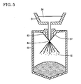
- iron masses to be used as a material of the iron particles are first put into a vacuum induction furnace 51, and then a highfrequency power is applied to the vacuum induction furnace 51. This makes the iron masses in the vacuum induction furnace 51 be fused into the molten liquid 56.
- the molten liquid 56 is poured into the molten liquid introduction tube 53 while spraying pressurized water 57 to the spray nozzle 54.
- the molten liquid 56 is atomized by the sprayed pressurized water 57, and rapidly cooled in the spray tower 52 to form iron powder consisting of the iron particles 10.
- the iron powder may be heated to a temperature of at least 500°C under a hydrogen or inert gas atmosphere after the abovementioned atomizing process. This can release the strain and the stress existing inside the iron particles 10, thus reducing the hardness of the iron particles 10.
- the iron particles 10 it is also possible to deform the iron particles 10 so as to have an irregular shape, a large surface roughness and a jagged outline by appropriate adjustment of the conditions such as the pressure of water spray and the water temperature.
- use of an atomizing method using water results in a more complicated texture being formed on the surface of the iron particles 10 than use of an atomizing method using a gas.
- the obtained iron powder is treated with phosphoric acid to form the insulating films 20 on the surface of the iron particles 10, thus producing the composite magnetic particles 30.
- These insulating films 20 are positioned between the iron particles 10 so as to serve as an insulating layer. Covering the iron particles 10 with the insulating films 20 can improve the electrical resistance ⁇ of the resulting dust core. This can prevent an eddy current from passing through the iron particles 10 and as a result, the iron loss in the dust core caused by the eddy current can be reduced.
- the insulating films 20 may contain oxides.
- oxides Several kinds of materials may be used for forming the insulating films 20 containing oxides, for example, iron phosphate having phosphorous and iron, manganese phosphate, zinc phosphate, calcium phosphate and aluminum phosphate, as well as oxide insulators such as silicon oxide, titanium oxide, aluminum oxide and zirconium oxide.
- the insulating films 20 may consist of a single layer, as shown in the drawing, or a plurality of layers.
- the average thickness of the insulating films 20 is preferably 5 nm to 100 nm. This average thickness is determined by calculating the equivalent thickness from the film composition obtained by a composition analysis (transmission electron microscope energy dispersive X-ray spectroscopy (TEM-EDX)) and the element content obtained by inductively coupled plasma-mass spectrometry (ICP-MS) and then performing direct visual observation of the film on a TEM image to confirm that the calculated equivalent thickness is of the correct order of magnitude.
- TEM-EDX transmission electron microscope energy dispersive X-ray spectroscopy
- ICP-MS inductively coupled plasma-mass spectrometry
- the first organic matter to be used as an integrity enhancer which consists of thermoplastic resin and non-thermoplastic resin
- the second organic matter to be used as a lubricant which consists of a higher fatty acid-based lubricant
- the first organic matter include thermoplastic resin such as thermoplastic polyimide, thermoplastic polyamide, thermoplastic polyamide-imide, polyphenylene sulfide, polyamide-imide, polyethersulfone, polyetherimide and polyetheretherketone, as well as non-thermoplastic resin such as high-molecular-weight polyethylene, wholly aromatic polyester and wholly aromatic polyimide.
- this high-molecular-weight polyethylene represents polyethylene whose molecular weight is 100,000 or more.
- the second organic matter include zinc stearate, lithium stearate, calcium stearate, magnesium stearate, lithium palmitate, calcium palmitate, lithium oleate, calcium oleate and other higher fatty acid-based compounds.
- the composite magnetic particles 30 and the organic matter 40 are mixed using a V-type mixer.
- the amounts of the first and second organic matter to be mixed are separately adjusted so that their content ratios account for 0.001 wt% to 0.2 wt% of the expected weight of the compact produced in a subsequent process.
- the organic matter 40 may consist of both or either the first and second organic matter.
- any technique such as mechanical alloying, vibratory ball milling, planetary ball milling, mechanofusion, coprecipitation, chemical vapor deposition (CVD), physical vapor deposition (PVD), plating, sputtering, vapor deposition and sol-gel process may be used.
- the obtained powder mixture is then subjected to pressure-forming.
- the band heater 77 placed in the mold 71 is turned on to heat the inner wall 73 of the die 72 to a temperature of at least 40°C.
- the powder mixture obtained in the previous step may be heated instead of the inner wall 73, or both the inner wall 73 and the powder mixture may be heated. Preferably, these components are heated to a temperature from 80°C to 200°C.
- a lubricant introduction portion 78 is positioned above the space 74 surrounded by the inner wall 73. From the spray nozzle of this lubricant introduction portion 78, a mold lubricant 91 is sprayed into the space 74 using compressed air. This makes the mold lubricant 91 adhere to the inner wall 73 and the bottom 76 of the mold 71.
- the mold lubricant 91 is schematically illustrated as powder in the drawing, the mold lubricant 91 may be a liquid, and the adhesion technique may be either a wet or a dry technique.
- mold lubricant 91 examples include metal soap, polyethylene, amide wax, polyamide, polypropylene, polyacrylate, polymethacrylate, fluororesin and a layered lubricant.
- a combined lubricant obtained by mixing any two or more kinds of the abovementioned material may be used.
- a shoe 79 is positioned above the space 74, and then the powder mixture 15 obtained in the previous step is introduced to the space 74 from the shoe 79.
- an upper punch 80 is positioned above the space 74.
- the upper punch 80 is then lowered to press the powder mixture 15 under a certain pressure, for example, from 700 MPa to 1500 MPa.
- the ambient atmosphere is preferably an inert gas or under reduced pressure. This can prevent the powder mixture from being oxidized due to oxygen in the air.
- the organic matter 40 serves as a lubricant in the interface between the adjacent composite magnetic particles 30 mainly by the effect of the second organic matter contained therein. This avoids introduction of strain to the iron particles 10 and destruction of the insulating films 20 caused by excessive friction during the pressure-forming process.
- the compact 16 obtained by pressure-forming is removed from the space 74.
- the compact 16 is then heated at a temperature higher than the glass transition temperature of the organic matter 40 and not more than the thermal decomposition temperature of the organic matter 40.
- the organic matter 40 can be protected from thermal decomposition and fill gaps between the composite magnetic particles 30 sufficiently. This can reinforce the bonds between the composite magnetic particles 30, thus improving the integrity of the compact 16 mainly by the effect of the first organic matter contained in the organic matter 40.
- the heating process can also remove the strain and the dislocation that have occurred inside the compact 16 during the pressure-forming process.
- the iron particles 10 can be plastically deformed with ease in the pressure-forming process, because of the low hardness of iron particles 10 with the Vickers hardness HV of less than 800. Therefore, the composite magnetic particles 30 are coupled with each other through intricate entanglement, and thus the bonds between them are reinforced. This can improve the integrity of the compact 16 produced in the pressure-forming process and enables processing of the compact 16, for example, to cut off the compact 16, without any damage thereto.
- the dust core produced in this way can be used in a wide variety of products including electronics such as a choke coil, a switching power device and a magnetic head, components of a motor, solenoids for automobiles, magnetic sensors and solenoid valves.
- electronics such as a choke coil, a switching power device and a magnetic head, components of a motor, solenoids for automobiles, magnetic sensors and solenoid valves.
- magnetic components such as the dust core produced in this embodiment, any other type of common powder compacts, for example, those used as mechanical components, can be fabricated.
- the soft magnetic material and the method of producing a powder compact according to the present invention were evaluated using the following examples.
- Bonderite coating wherein an iron phosphate solution is used, was applied to some types of iron powder to form the iron phosphate films acting as the insulating films 20 on the surface of the iron particles 10, thus producing the composite magnetic particles 30.
- the thickness of the insulating films 20 was adjusted by changing the concentration of the solution.
- the density of the compacts was 7.5 g/cm 3
- the shape of the compacts was the same as that of 20-mm JIS samples in accordance with the specifications of JIS transverse test.
- the transverse strength of the compacts obtained in the steps described above was measured by carrying out the transverse test according to JIS.
- the measured values of the transverse strength accompanied by data of the iron particles 10 and the insulating films 20 constituting each sample compact are shown in Table I.
- the composite magnetic particles 30 were prepared by forming several types of insulating films 20 on the surface of the iron powder used to prepare the compact of Sample F in Example 1, while changing the thickness of the insulating films.
- the compacts having the same shape as that of the abovementioned JIS samples were produced from the obtained composite magnetic particles 30, and designated as Samples 1 to 20.
- ring-shaped compacts were produced from the same composite magnetic particles 30 and designated as Samples 1 to 20.
- the transverse test was performed in a similar way to that in Example 1 in order to measure the transverse strength of each compact.
- their eddy current loss factor was measured in a magnetic field wherein the magnetic field strength was up to 1 Tesla (T).
- T The measured values of the transverse strength and the eddy current loss factor accompanied by data of the iron particles 10 and the insulating films 20 constituting each sample compact are shown in Table II.
- the insulating films 20 having a thickness smaller than 5 nm provided only insufficient reduction of the eddy current loss factor.
- the insulating films 20 having a thickness larger than 100 nm reduced the eddy current loss factor sufficiently, but also reduced the transverse strength slightly. This may be due to the fact that, the texture of the iron particles 10 could not be transferred to the surface of the insulating films 20 since the thickness of the insulating films 20 was excessively large, and as a result, entanglement of the composite magnetic particles 30 was also insufficient.
- the samples wherein the thickness of the insulating films 20 was 5 nm to 100 nm achieved both an excellent integrity and a decreased eddy current loss factor.
- Example 2 In a similar way to that in Example 2, the transverse strength of the compacts having the same shape as that of the JIS samples was measured, and the eddy current loss factor of the ring-shaped compacts was measured.
- the measured values of the transverse strength and the eddy current loss factor accompanied by data of the organic matters added in each sample compact are shown in Table III.
- “Added resin” in the table corresponds to the first organic matter to be used as an integrity enhancer described in the embodiments above
- “Lubricant” corresponds to the second organic matter used as a lubricant described in the embodiments above.
- the present invention is applicable in manufacturing motor cores, solenoid valves, reactors or other electromagnetic components produced by pressure-forming of soft magnetic powder.
Landscapes
- Engineering & Computer Science (AREA)
- Power Engineering (AREA)
- Manufacturing & Machinery (AREA)
- Chemical & Material Sciences (AREA)
- Dispersion Chemistry (AREA)
- Soft Magnetic Materials (AREA)
- Powder Metallurgy (AREA)
Applications Claiming Priority (1)
| Application Number | Priority Date | Filing Date | Title |
|---|---|---|---|
| PCT/JP2005/005890 WO2006106566A1 (fr) | 2005-03-29 | 2005-03-29 | Matiere magnetique tendre et procede de production de comprime en cru |
Publications (2)
| Publication Number | Publication Date |
|---|---|
| EP1868213A1 true EP1868213A1 (fr) | 2007-12-19 |
| EP1868213A4 EP1868213A4 (fr) | 2011-01-26 |
Family
ID=37073135
Family Applications (1)
| Application Number | Title | Priority Date | Filing Date |
|---|---|---|---|
| EP05727280A Withdrawn EP1868213A4 (fr) | 2005-03-29 | 2005-03-29 | Matiere magnetique tendre et procede de production de comprime en cru |
Country Status (4)
| Country | Link |
|---|---|
| US (1) | US7641745B2 (fr) |
| EP (1) | EP1868213A4 (fr) |
| CN (1) | CN101151686A (fr) |
| WO (1) | WO2006106566A1 (fr) |
Cited By (5)
| Publication number | Priority date | Publication date | Assignee | Title |
|---|---|---|---|---|
| CN101577163B (zh) * | 2008-03-28 | 2011-12-14 | 株式会社东芝 | 高频磁性材料及其制造方法 |
| EP2727217A4 (fr) * | 2011-06-30 | 2015-07-15 | Persimmon Technologies Corp | Matériau magnétique structuré |
| US10022789B2 (en) | 2011-06-30 | 2018-07-17 | Persimmon Technologies Corporation | System and method for making a structured magnetic material with integrated particle insulation |
| US10476324B2 (en) | 2012-07-06 | 2019-11-12 | Persimmon Technologies Corporation | Hybrid field electric motor |
| US10570494B2 (en) | 2013-09-30 | 2020-02-25 | Persimmon Technologies Corporation | Structures utilizing a structured magnetic material and methods for making |
Families Citing this family (7)
| Publication number | Priority date | Publication date | Assignee | Title |
|---|---|---|---|---|
| CN101151686A (zh) * | 2005-03-29 | 2008-03-26 | 住友电气工业株式会社 | 软磁性材料和制造压粉体的方法 |
| JP5960476B2 (ja) * | 2012-03-30 | 2016-08-02 | 株式会社ケーヒン | 磁気異方性塑性加工品及びその製造方法と、それを用いた電磁装置 |
| US9719159B2 (en) * | 2014-09-24 | 2017-08-01 | Cyntec Co., Ltd. | Mixed magnetic powders and the electronic device using the same |
| KR102105390B1 (ko) * | 2015-07-31 | 2020-04-28 | 삼성전기주식회사 | 자성 분말 및 이를 포함하는 코일 전자부품 |
| CN108039275A (zh) * | 2017-12-12 | 2018-05-15 | 江西中磁科技协同创新有限公司 | 一种软磁材料的成型模具 |
| CN109979701B (zh) * | 2019-05-17 | 2020-12-22 | 广东省材料与加工研究所 | 一种双层无机绝缘包覆软磁粉末及其制备方法 |
| CN114477988B (zh) * | 2022-03-28 | 2023-03-24 | 天通控股股份有限公司 | 一种易成型、高强度铁氧体材料及其制备方法 |
Family Cites Families (12)
| Publication number | Priority date | Publication date | Assignee | Title |
|---|---|---|---|---|
| US3999216A (en) * | 1970-07-30 | 1976-12-21 | Eastman Kodak Company | Material for magnetic transducer heads |
| EP0406580B1 (fr) * | 1989-06-09 | 1996-09-04 | Matsushita Electric Industrial Co., Ltd. | Matériau composite et son procédé de préparation |
| JPH07245209A (ja) * | 1994-03-02 | 1995-09-19 | Tdk Corp | 圧粉コアおよびその製造方法 |
| SE9401392D0 (sv) | 1994-04-25 | 1994-04-25 | Hoeganaes Ab | Heat-treating of iron powders |
| SE9402497D0 (sv) | 1994-07-18 | 1994-07-18 | Hoeganaes Ab | Iron powder components containing thermoplastic resin and methods of making same |
| JP2001102207A (ja) | 1999-09-30 | 2001-04-13 | Tdk Corp | 圧粉磁心の製造方法 |
| JP3986043B2 (ja) | 2001-02-20 | 2007-10-03 | 日立粉末冶金株式会社 | 圧粉磁心及びその製造方法 |
| JP2003129104A (ja) * | 2001-10-24 | 2003-05-08 | Sanyo Special Steel Co Ltd | 圧粉コア用粉末 |
| EP1447824B8 (fr) | 2001-10-29 | 2015-10-28 | Sumitomo Electric Sintered Alloy, Ltd. | Procede de production d'un materiau magnetique composite |
| JP2005129716A (ja) | 2003-10-23 | 2005-05-19 | Sumitomo Electric Ind Ltd | 圧粉磁心 |
| JP4278147B2 (ja) | 2003-11-12 | 2009-06-10 | 株式会社豊田中央研究所 | 磁心用粉末、圧粉磁心およびそれらの製造方法 |
| CN101151686A (zh) * | 2005-03-29 | 2008-03-26 | 住友电气工业株式会社 | 软磁性材料和制造压粉体的方法 |
-
2005
- 2005-03-29 CN CNA2005800493667A patent/CN101151686A/zh active Pending
- 2005-03-29 WO PCT/JP2005/005890 patent/WO2006106566A1/fr not_active Ceased
- 2005-03-29 US US11/909,962 patent/US7641745B2/en not_active Expired - Lifetime
- 2005-03-29 EP EP05727280A patent/EP1868213A4/fr not_active Withdrawn
Cited By (12)
| Publication number | Priority date | Publication date | Assignee | Title |
|---|---|---|---|---|
| CN101577163B (zh) * | 2008-03-28 | 2011-12-14 | 株式会社东芝 | 高频磁性材料及其制造方法 |
| US8354037B2 (en) | 2008-03-28 | 2013-01-15 | Kabushiki Kaisha Toshiba | High-frequency magnetic material and method of manufacturing the same |
| EP2727217A4 (fr) * | 2011-06-30 | 2015-07-15 | Persimmon Technologies Corp | Matériau magnétique structuré |
| US9205488B2 (en) | 2011-06-30 | 2015-12-08 | Persimmon Technologies Corporation | Structured magnetic material having domains with insulated boundaries |
| US9364895B2 (en) | 2011-06-30 | 2016-06-14 | Persimmon Technologies Corporation | System and method for making a structured magnetic material via layered particle deposition |
| US9381568B2 (en) | 2011-06-30 | 2016-07-05 | Persimmon Technologies Corporation | System and method for making structured magnetic material from insulated particles |
| US10022789B2 (en) | 2011-06-30 | 2018-07-17 | Persimmon Technologies Corporation | System and method for making a structured magnetic material with integrated particle insulation |
| US10730103B2 (en) | 2011-06-30 | 2020-08-04 | Persimmon Technologies Corporation | System and method for making a structured material |
| US11623273B2 (en) | 2011-06-30 | 2023-04-11 | Persimmon Technologies Corporation | System and method for making a structured material |
| US12103069B2 (en) | 2011-06-30 | 2024-10-01 | Persimmon Technologies Corporation | System and method for making a structured material |
| US10476324B2 (en) | 2012-07-06 | 2019-11-12 | Persimmon Technologies Corporation | Hybrid field electric motor |
| US10570494B2 (en) | 2013-09-30 | 2020-02-25 | Persimmon Technologies Corporation | Structures utilizing a structured magnetic material and methods for making |
Also Published As
| Publication number | Publication date |
|---|---|
| WO2006106566A1 (fr) | 2006-10-12 |
| EP1868213A4 (fr) | 2011-01-26 |
| US7641745B2 (en) | 2010-01-05 |
| CN101151686A (zh) | 2008-03-26 |
| US20080253917A1 (en) | 2008-10-16 |
Similar Documents
| Publication | Publication Date | Title |
|---|---|---|
| EP2492031B1 (fr) | Noyau de poudre et son procédé de production | |
| EP2947670B1 (fr) | Procédé de fabrication de noyau magnétique en poudre, noyau magnétique en poudre et composant de bobine | |
| EP2518740B1 (fr) | Procédé de production d'un réacteur | |
| EP1808242B1 (fr) | Procede de fabrication de poudre de metal magnetique souple revetue d'un film oxyde contenant du mg et procede de fabrication de materiau magnetique souple composite uitilisant ladite poudre | |
| EP2153921B1 (fr) | Procédé de production de poudre métallique et d'un noyau magnétique de poudre | |
| EP3118865B1 (fr) | Noyau magnétique, composant de bobine et procédé de fabrication de noyau magnétique | |
| EP1840907B1 (fr) | Matériau magnétique souple et noyau de poussière | |
| EP2189994B1 (fr) | Noyau pour réacteurs, son procédé de fabrication et réacteur correspondant | |
| JP5050745B2 (ja) | リアクトル用コアとその製造方法およびリアクトル | |
| EP2380685A1 (fr) | Procédé de fabrication de poudre pour métallurgie, procédé de fabrication de noyau aggloméré, noyau aggloméré et pièce de bobine | |
| EP1870911A1 (fr) | Materiau magnetique souple et noyau a poudre de fer | |
| US7641745B2 (en) | Soft magnetic material and method of producing powder compact | |
| EP2060344A1 (fr) | Noyau magnétique à poudre et poudre à base de fer pour noyau magnétique à poudre | |
| EP1737003B1 (fr) | Matériau magnétique doux et noyau de poudre | |
| EP2330602B1 (fr) | Matériau magnétique composite et procédé de fabrication associé | |
| CN104335300A (zh) | 压粉磁芯、压粉磁芯的制造方法以及压粉磁芯的涡电流损耗的推定方法 | |
| JP2012238866A (ja) | リアクトル用コアとその製造方法およびリアクトル | |
| JP2007092162A (ja) | 高圧縮性鉄粉、およびそれを用いた圧粉磁芯用鉄粉と圧粉磁芯 | |
| CN1938114B (zh) | 软磁性材料的制造方法、软磁性粉末和压粉磁芯 | |
| JP2005248274A (ja) | 軟磁性材料および圧粉成形体の製造方法 | |
| US11699542B2 (en) | Dust core | |
| JP2007231330A (ja) | 圧粉磁心用金属粉末および圧粉磁心の製造方法 | |
| JPH03278501A (ja) | 軟質磁心材料およびその製造方法 | |
| EP1486990A2 (fr) | Matériau magnétique composite et procédé de préparation associé | |
| JP2005248273A (ja) | 軟磁性材料および圧粉磁心の製造方法 |
Legal Events
| Date | Code | Title | Description |
|---|---|---|---|
| PUAI | Public reference made under article 153(3) epc to a published international application that has entered the european phase |
Free format text: ORIGINAL CODE: 0009012 |
|
| 17P | Request for examination filed |
Effective date: 20071001 |
|
| AK | Designated contracting states |
Kind code of ref document: A1 Designated state(s): DE ES FR |
|
| DAX | Request for extension of the european patent (deleted) | ||
| RBV | Designated contracting states (corrected) |
Designated state(s): DE ES FR |
|
| A4 | Supplementary search report drawn up and despatched |
Effective date: 20101228 |
|
| 17Q | First examination report despatched |
Effective date: 20110315 |
|
| STAA | Information on the status of an ep patent application or granted ep patent |
Free format text: STATUS: THE APPLICATION IS DEEMED TO BE WITHDRAWN |
|
| 18D | Application deemed to be withdrawn |
Effective date: 20110726 |