EP1868227A1 - Lampe a decharge sans electrode et source lumineuse comprenant celle-ci - Google Patents
Lampe a decharge sans electrode et source lumineuse comprenant celle-ci Download PDFInfo
- Publication number
- EP1868227A1 EP1868227A1 EP06729745A EP06729745A EP1868227A1 EP 1868227 A1 EP1868227 A1 EP 1868227A1 EP 06729745 A EP06729745 A EP 06729745A EP 06729745 A EP06729745 A EP 06729745A EP 1868227 A1 EP1868227 A1 EP 1868227A1
- Authority
- EP
- European Patent Office
- Prior art keywords
- bulb
- ferrule
- protruding portion
- discharge lamp
- electrodeless discharge
- Prior art date
- Legal status (The legal status is an assumption and is not a legal conclusion. Google has not performed a legal analysis and makes no representation as to the accuracy of the status listed.)
- Withdrawn
Links
Images



Classifications
-
- H—ELECTRICITY
- H01—ELECTRIC ELEMENTS
- H01J—ELECTRIC DISCHARGE TUBES OR DISCHARGE LAMPS
- H01J65/00—Lamps without any electrode inside the vessel; Lamps with at least one main electrode outside the vessel
- H01J65/04—Lamps in which a gas filling is excited to luminesce by an external electromagnetic field or by external corpuscular radiation, e.g. for indicating plasma display panels
- H01J65/042—Lamps in which a gas filling is excited to luminesce by an external electromagnetic field or by external corpuscular radiation, e.g. for indicating plasma display panels by an external electromagnetic field
- H01J65/048—Lamps in which a gas filling is excited to luminesce by an external electromagnetic field or by external corpuscular radiation, e.g. for indicating plasma display panels by an external electromagnetic field the field being produced by using an excitation coil
-
- H—ELECTRICITY
- H01—ELECTRIC ELEMENTS
- H01J—ELECTRIC DISCHARGE TUBES OR DISCHARGE LAMPS
- H01J65/00—Lamps without any electrode inside the vessel; Lamps with at least one main electrode outside the vessel
-
- H—ELECTRICITY
- H01—ELECTRIC ELEMENTS
- H01J—ELECTRIC DISCHARGE TUBES OR DISCHARGE LAMPS
- H01J65/00—Lamps without any electrode inside the vessel; Lamps with at least one main electrode outside the vessel
- H01J65/04—Lamps in which a gas filling is excited to luminesce by an external electromagnetic field or by external corpuscular radiation, e.g. for indicating plasma display panels
- H01J65/042—Lamps in which a gas filling is excited to luminesce by an external electromagnetic field or by external corpuscular radiation, e.g. for indicating plasma display panels by an external electromagnetic field
Definitions
- the present invention relates to an electrodeless discharge lamp having no electrode in a bulb into which discharge gas is filled, and generates discharge in the discharge gas by liberating high frequency electromagnetic field generated by supplying high frequency current to an induction coil to the discharge gas, and relates to a lighting apparatus using the same.
- the electrodeless discharge lamp is configured that the discharge gas filled in the bulb is activated by high frequency electromagnetic field generated by supplying high frequency current to the induction coil, and ultraviolet light emitted at that time is converted into visible light through fluorescent material. Since the electrodeless discharge lamp apparatus has a configuration that no electrode inside, non-lighting due to deterioration of the electrode may not occur, and thus, it is relatively longevity life in comparison with generic fluorescent lamp.
- a conventional electrodeless discharge lamp shown in Japanese Laid-Open Patent Publication No. 7-272688 or Japanese Laid-Open Utility Model Publication No. 6-5006 uses a bismuth-indium amalgam as a luminescent material. According to this amalgam, it is possible to obtain a higher optical output in a wide range than the optical output at ambient air temperature 25 degrees Celsius, even when ambient air temperature changes.
- a high mercury vapor pressure is necessary to realize a high optical output, there, however, is a disadvantage that start-up of the lamp is slower because a time until reaching a temperature value that it is necessary for evaporation of mercury.
- the bismuth-indium amalgam was used, a consequence that it is necessary for approximately 1 minute to secure optical output of 60% with respect to optical output at the time of stable lighting was provided.
- the present invention is conceived to solve the above mentioned problems, and a purpose of the present invention is to provide an electrodeless discharge lamp a lighting apparatus using the same, which can maintain a high optical output even when the posture of installation is changed by providing the coldest spot in the bulb and controlling the temperature of the coldest spot.
- An electrodeless discharge lamp in accordance with an aspect of the present invention comprises a bulb into which discharge gas and mercury which is controlled at a temperature of a coldest spot are filled, a power coupler generating high frequency electromagnetic field, and a ferrule for coupling the bulb and the power coupler, wherein the bulb is configured of a barrel formed of a transparent material and having an opening, and a sealing member welded to the opening of the barrel and having a cylindrical cavity; a protrusion, which becomes a coldest spot when the lamp is lit in a state that the ferrule is disposed upward, is formed at an apex of the bulb; and a protruding portion is formed in a vicinity of a portion of the bulb just above the ferrule so that the vicinity of the portion of the bulb just above the ferrule serves as a coldest spot when the lamp is lit in a state that the ferrule is disposed downward.
- the protruding portion When the protruding portion is formed to protrude inward of the bulb, a volume of a discharge space near to the protruding portion is partially shrunk, so that luminescence in the vicinity of the protruding portion is restrained when the electrodeless discharge lamp is lit in base-down lighting, and a part of heat generated corresponding to the luminescence is shielded by the protruding portion. Consequently, a temperature rise of the portion just above the ferrule, that is, the bulb neck portion is restrained, and thus, the bulb neck portion becomes the coldest spot.
- the protruding portion When the protruding portion is formed to protrude outward of the bulb, inside concavity of the protruding portion is positioned away from a portion where the discharge actually occurs, so that heat generated corresponding to the luminescence is hard to transmit to the protruding portion. Consequently, a temperature rise in the protruding portion is restrained, and thus the protruding portion becomes the coldest spot. In this way, although a location of the coldest spot is changed corresponding to the posture of installation of the electrodeless discharge lamp, the temperature value of the coldest spot can be maintained substantially constant in each case, so that a constant optical output is provided regardless of the posture of installation of the electrodeless discharge lamp.
- FIG. 1 shows a configuration of an electrodeless discharge lamp according to the first embodiment.
- the electrodeless discharge lamp 1 according to the first embodiment comprises a bulb 10 into which discharge gas and mercury which is controlled with temperature of the coldest spot, and a power coupler 20 which generates high frequency electromagnetic field.
- the bulb 10 is a hermetic container configured of a substantially spherical barrel 14 formed of a transparent material and having a circular opening, and a sealing member 11 welded to the circular opening of the barrel 14 and having a substantially cylindrical cavity 5 and an exhaust tube 8 formed at a center portion of the cavity 5.
- the power coupler 20 is configured of an induction coil for generating an induction field and a ferrite core, and engaged with the cavity 5 so that the exhaust tube 8 is located at the center thereof.
- a protective coating 2 and a phosphor coating 3 are applied to an inner peripheral face of the spherical barrel 14. Similarly, the protective coating 2 and the phosphor coating 3 are applied to an outer peripheral face of the cavity 5 of the sealing member 11 (It is partially illustrated in the figure). Therefore, the protective coating 2 and the phosphor coating 3 are applied to substantially whole area of an inner peripheral face of the bulb 10.
- metal oxide such as Al 2 O 3 is used as a binding agent of the fluorescent material, and the phosphor coating 3 is protected by increasing quantity of addition of the agent so as to prevent deterioration of the fluorescent material.
- the binding agent Y 2 O 3 or MgO can be used other than Al 2 O 3 .
- a mounting structure such as a bayonet not show in the figure is provided on the ferrule 15 and a pedestal of the power coupler 20, respectively, so that the bulb 10 which is integrated with the ferrule 15 is detachably attached to the power coupler 20.
- a protrusion 4 is formed at an apex of the bulb 10 so that it becomes the coldest shot when the lamp is lit in a state that the ferrule 15 is disposed upward (base-up lighting).
- the protruding portion 17 functions as a discharge shielding means so that the vicinity of the protruding portion 17 becomes the coldest spot. Details are described later.
- a rare gas such as argon or krypton is enclosed in the inside of the bulb 10.
- a metal container 13 made of iron-nickel alloy is established in an inside of the exhaust tube 8, and Zn-Hg of total quantity about 17 mg and 50:50 of a weight ration is filled in the metal container 13 so as to emit mercury for controlling mercury vapor pressure.
- a recess 9 is formed on an inner peripheral face of the exhaust tube 8 to fix a location of the metal container 13, and a glass rod 12 is provided in the exhaust tube 8.
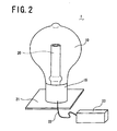
- FIG. 2 shows a configuration of the lighting apparatus comprising the electrodeless discharge lamp according to the first embodiment of the present invention.
- the configuration of this lighting apparatuses is similar in the second to fourth embodiment which will be described later.
- the power coupler 20 constituting the electrodeless discharge lamp 1 is fixed on a heatsink 21, and the heatsink 21 is installed on a ceiling, a side wall, or a floor of a building.
- the power coupler 20 is configured of an induction coil for generating high frequency electromagnetic field and a ferrite core, and terminals of the induction coil are connected to a lightning circuit 23 through an electric cable 22. Then, the lighting apparatus comprising the electrodeless discharge lamp 1 is configured when the bulb 10 which is integrated with the ferrule 15 is attached to the power coupler 20. Since a high frequency current supplied to the induction coil of the power coupler 20 has a lower frequency of several hundred kHz, the ferrite core (magnetic core) inside the induction coil.
- the protruding portion 17 is formed just above the ferrule 15 of the bulb 10, that is, in the bulb neck portion 19, a volume of a discharge space in the vicinity of the protruding portion 17 is partially shrunk.
- the electrodeless discharge lamp 1 is lit in the base-down lighting, luminescence in the vicinity of the protruding portion 17 is restrained, and a part of heat which occurs following to the luminescence is shielded by the protruding portion 17. Consequently, a temperature rise of the bulb neck portion 19 is restrained, and thus, the bulb neck portion 19 becomes the coldest spot.
- the protrusion 4 formed at the apex of the bulb 10 becomes the coldest spot similar to the conventional case.
- the temperature value of the coldest spot could be maintained substantially constant in each case, when the temperature of the coldest spot was measured. Consequently, a constant optical output can be provided regardless of the posture of installation of the electrodeless discharge lamp 1.
- the protruding portion 17 is formed annularly along a circumferential direction of the cavity 5, it, however, is not limited to this. It is sufficient that the protruding portion 17 should be formed at least a portion of the outer peripheral face of the cavity 5. Alternatively, the protruding portion 17 may be formed at a plurality of portions along the circumferential direction of the cavity 5.
- FIG. 3 shows a configuration of an electrodeless discharge lamp according to the second embodiment. Since the portions, to which the same codes as those of the electrodeless discharge lamp according to the first embodiment shown in FIG. 1 are applied, are substantially the same, description of them is omitted.
- an annular protruding portion 16 which protrudes outward along the circumferential direction of the barrel 14 constituting the bulb 10, is formed in the vicinity of the sealing portion of the bulb 10, that is, just above the ferrule 15 when the ferrule 15 is disposed upward.
- an inside concavity of the protruding portion 16 is positioned away from a portion where discharge actually occurs, and thus, heat generated corresponding to the luminescence is hard to transmit to the protruding portion 16. Consequently, a temperature rise in the protruding portion 16 is restrained.
- the protruding portion 16 becomes the coldest spot.
- the protrusion 4 formed at the apex of the bulb 10 becomes the coldest spot similar to the first embodiment. In this way, although a location of the coldest spot is changed corresponding to the posture of installation of the electrodeless discharge lamp 1, it was confirmed that the temperature value of the coldest spot could be maintained substantially constant in each case, when the temperature of the coldest spot was measured. Consequently, a constant optical output can be provided regardless of the posture of installation of the electrodeless discharge lamp 1.
- the protruding portion 16 is formed annularly along a circumferential direction of the barrel 14, it, however, is not limited to this. It is sufficient that the protruding portion 16 should be formed at least a portion of the outer peripheral face of the barrel 14. Alternatively, the protruding portion 16 may be formed at a plurality of portions along the circumferential direction of the barrel 14.
- FIG. 4 shows a configuration of a lighting apparatus comprising the electrodeless discharge lamp according to the second embodiment of the present invention.
- this lighting apparatus is different only the shape of the bulb 10 from the lighting apparatus of the above mentioned first embodiment, the description is omitted.
- FIG. 5 shows a configuration of an electrodeless discharge lamp according to the third embodiment.
- the power coupler 20 to be fit into the cavity 5 is also illustrated by solid lines.
- the portions, to which the same codes as those of the electrodeless discharge lamp according to the first embodiment shown in FIG. 1 or the second embodiment show in FIG. 3 are applied, are substantially the same, description of them is omitted.
- the bulb 10 in the third embodiment possesses the annular protruding portion 17 formed along the outer peripheral face of the cavity 5 which is the characteristic of the first above embodiment and the annular protruding portion 16 formed along the circumferential direction of the barrel 14 which the characteristic of the second embodiment. Furthermore, spring members 18, which are fitted to the inside concavity of the protruding portion 17, are provided on the power coupler 20.
- the spring members 18 provided on the power coupler 20 are fit to utilizing the inside concavity the protruding portion 17, it is possible to fix the bulb 10 and the power coupler 20 stably.
- the lighting apparatus according to the third embodiment is substantially the same as that in the second embodiment shown in FIG. 4, illustration and description are omitted.
- FIG. 6 shows a configuration of an electrodeless discharge lamp according to the fourth embodiment.
- the exhaust tube 8 is provided at the center of the cavity 5
- the protrusion 4 and/or the protruding portion 16 are/is used as an exhaust tube or a part of the same in the fourth embodiment when forming the protrusion 4 at the apex of the bulb 10 and the protruding portion 16.
- the shape of the sealing member 11 having the cavity 5 can be simplified, and thus, a manufacturing cost of the electrodeless discharge lamp can be reduced.
- the exhaust tube 8 is used to exhaust an internal air and to full a discharge gas such as argon or krypton after welding the barrel 14 and the sealing member 11 in the manufacturing processes of the bulb 10. Therefore, it is not necessarily disposed at the center of the cavity 5. As for the reason why the exhaust tube 8 is conventionally provided at the center of the cavity 5, it is recited to ease the manufacturing of the spherical barrel 14 and to enhance a good appearance of the electrodeless discharge lamp 1. However, it is not need to consider the above reason in the electrodeless discharge lamp 1 in accordance with the present invention, since the protrusion 4 is formed at the apex of the bulb 10.
- a single protruding portion 16 which protrudes outward along the circumferential direction of the barrel 14 constituting the bulb 10, is formed in the vicinity of the sealing portion of the bulb 10, that is, just above the ferrule 15 in a state that the ferrule 15 is disposed downward.
- the metal container 13 into which Zn-Hg is filled is provided in the protruding portion 16. Then, both of the protrusion 4 and the protruding portion 16 are used as the exhaust tubes or a part of the same to exhaust impurity gas such as air in the bulb 10 and to fill a discharge gas therein.
- an exhaust tube 8A having a smaller diameter is formed on the protrusion 4 at the apex of the bulb 10. This is a trace that a glass pile was welded to the protrusion 4 of the barrel 14 in the first embodiment shown in FIG. 1, for example, and used as the exhaust tube, and an opening of the glass pipe was sealed by welding after filling the discharge gas.
- the protruding portion 16 serving as an exhaust tube 8B having a smaller diameter is formed in the bulb neck portion 19 of the bulb 10. This is a trace that a glass pile is welded to the bulb neck portion 19 of the barrel 14 in the first embodiment shown in FIG. 1, for example, and used as the exhaust tube, and an opening of the glass pipe was sealed by welding after disposition of the metal container 13 and filling the discharge gas.
- the protruding portions 16 each serving as the exhaust tube 8B may be formed at a plurality places so that the same effect can be obtained.
- the exhaust tube 8A may be formed on the protrusion 4 at the apex of the bulb 10 and the metal container 13 may be disposed inside the exhaust tube 8A in the configuration of the first to third embodiment, similar to the fourth embodiment.
- the exhaust tube 8 at the center of the cavity 5 can be omitted.
- the exhaust tube 8A of the protrusion 4 can be omitted by enlarging the diameter of the exhaust tube 8B, that is, the protruding portion 16.
Landscapes
- Physics & Mathematics (AREA)
- Engineering & Computer Science (AREA)
- Plasma & Fusion (AREA)
- Electromagnetism (AREA)
- Discharge Lamps And Accessories Thereof (AREA)
- Non-Portable Lighting Devices Or Systems Thereof (AREA)
Applications Claiming Priority (2)
| Application Number | Priority Date | Filing Date | Title |
|---|---|---|---|
| JP2005084862A JP4872224B2 (ja) | 2005-03-23 | 2005-03-23 | 無電極放電ランプと同ランプを備えた照明器具 |
| PCT/JP2006/305778 WO2006101153A1 (fr) | 2005-03-23 | 2006-03-23 | Lampe a decharge sans electrode et source lumineuse comprenant celle-ci |
Publications (2)
| Publication Number | Publication Date |
|---|---|
| EP1868227A1 true EP1868227A1 (fr) | 2007-12-19 |
| EP1868227A4 EP1868227A4 (fr) | 2010-10-06 |
Family
ID=37023810
Family Applications (1)
| Application Number | Title | Priority Date | Filing Date |
|---|---|---|---|
| EP06729745A Withdrawn EP1868227A4 (fr) | 2005-03-23 | 2006-03-23 | Lampe a decharge sans electrode et source lumineuse comprenant celle-ci |
Country Status (6)
| Country | Link |
|---|---|
| US (1) | US7719173B2 (fr) |
| EP (1) | EP1868227A4 (fr) |
| JP (1) | JP4872224B2 (fr) |
| KR (1) | KR100893023B1 (fr) |
| CN (1) | CN100583386C (fr) |
| WO (1) | WO2006101153A1 (fr) |
Cited By (1)
| Publication number | Priority date | Publication date | Assignee | Title |
|---|---|---|---|---|
| US8198792B2 (en) | 2006-09-29 | 2012-06-12 | Panasonic Corporation | Electrodeless discharge lamp, lighting fixture, and method for manufacturing electrodeless discharge lamp |
Families Citing this family (7)
| Publication number | Priority date | Publication date | Assignee | Title |
|---|---|---|---|---|
| JP4915909B2 (ja) * | 2006-06-27 | 2012-04-11 | パナソニック株式会社 | 無電極放電灯及び照明器具 |
| JP4775350B2 (ja) * | 2006-09-29 | 2011-09-21 | パナソニック電工株式会社 | 無電極放電ランプ、及び照明器具、及び無電極放電ランプの製造方法 |
| JP2008159436A (ja) * | 2006-12-25 | 2008-07-10 | Matsushita Electric Works Ltd | 無電極放電ランプ及び照明器具 |
| JP4379532B2 (ja) * | 2007-07-26 | 2009-12-09 | パナソニック電工株式会社 | 照明装置 |
| JP5330856B2 (ja) * | 2009-02-20 | 2013-10-30 | パナソニック株式会社 | 無電極放電ランプおよび照明器具 |
| CN101964300B (zh) * | 2010-07-27 | 2013-01-09 | 丁春辉 | 一种双向高频无极灯灯泡及高频无极灯 |
| CN112820624A (zh) * | 2021-02-23 | 2021-05-18 | 北京朗菲霖科技研发有限公司 | 一种汞无极元素灯模块 |
Family Cites Families (14)
| Publication number | Priority date | Publication date | Assignee | Title |
|---|---|---|---|---|
| GB1125773A (en) * | 1965-08-12 | 1968-08-28 | Gen Electric Co Ltd | Improvements in or relating to low pressure sodium vapour electric discharge lamps |
| US4871944A (en) | 1979-02-13 | 1989-10-03 | North American Philips Corp. | Compact lighting unit having a convoluted fluorescent lamp with integral mercury-vapor pressure-regulating means, and method of phosphor-coating the convoluted envelope for such a lamp |
| NL7906203A (nl) * | 1979-08-15 | 1981-02-17 | Philips Nv | Lagedrukkwikdampontladingslamp. |
| US5294867A (en) * | 1992-03-13 | 1994-03-15 | Gte Products Corporation | Low pressure mercury vapor discharge lamp containing an amalgam |
| EP0565759B1 (fr) | 1992-04-15 | 1997-09-24 | International Business Machines Corporation | Méthode et dispositif pour le décodage des signaux F2F, lû d'un porteur d'informations magnétiques |
| US5581157A (en) | 1992-05-20 | 1996-12-03 | Diablo Research Corporation | Discharge lamps and methods for making discharge lamps |
| JPH07272688A (ja) | 1994-03-25 | 1995-10-20 | Philips Electron Nv | 無電極低圧水銀蒸気放電ランプ |
| JPH08153489A (ja) * | 1994-11-29 | 1996-06-11 | Toshiba Lighting & Technol Corp | 蛍光ランプおよびこれを用いた照明装置ならびに蛍光ランプ装置 |
| JPH0963543A (ja) * | 1995-08-21 | 1997-03-07 | Hitachi Ltd | 無電極ランプ |
| GB9521373D0 (en) * | 1995-10-18 | 1995-12-20 | Gen Electric | Electrodeless fluorescent lamp |
| JP3479657B2 (ja) * | 1996-05-24 | 2003-12-15 | 日立ライティング株式会社 | 無電極蛍光ランプの製造方法 |
| GB2314671A (en) * | 1996-06-26 | 1998-01-07 | Gen Electric | Electrodeless fluorescent lamp |
| KR20000015020A (ko) * | 1998-08-26 | 2000-03-15 | 김승곤 | 무전극 방전 램프 및 그 제조방법 |
| JP2001325920A (ja) * | 2000-05-12 | 2001-11-22 | Matsushita Electric Ind Co Ltd | 無電極放電ランプ |
-
2005
- 2005-03-23 JP JP2005084862A patent/JP4872224B2/ja not_active Expired - Fee Related
-
2006
- 2006-03-23 WO PCT/JP2006/305778 patent/WO2006101153A1/fr not_active Ceased
- 2006-03-23 KR KR1020077022778A patent/KR100893023B1/ko not_active Expired - Fee Related
- 2006-03-23 EP EP06729745A patent/EP1868227A4/fr not_active Withdrawn
- 2006-03-23 US US11/909,336 patent/US7719173B2/en not_active Expired - Fee Related
- 2006-03-23 CN CN200680009277A patent/CN100583386C/zh not_active Expired - Fee Related
Cited By (2)
| Publication number | Priority date | Publication date | Assignee | Title |
|---|---|---|---|---|
| US8198792B2 (en) | 2006-09-29 | 2012-06-12 | Panasonic Corporation | Electrodeless discharge lamp, lighting fixture, and method for manufacturing electrodeless discharge lamp |
| EP2063454A4 (fr) * | 2006-09-29 | 2012-12-12 | Panasonic Corp | Lampe a excitation haute frequence, dispositif d'eclairage et procede de fabrication d'une lampe a excitation haute frequence |
Also Published As
| Publication number | Publication date |
|---|---|
| CN101147231A (zh) | 2008-03-19 |
| WO2006101153A1 (fr) | 2006-09-28 |
| JP2006269229A (ja) | 2006-10-05 |
| KR100893023B1 (ko) | 2009-04-15 |
| CN100583386C (zh) | 2010-01-20 |
| KR20070110534A (ko) | 2007-11-19 |
| JP4872224B2 (ja) | 2012-02-08 |
| US7719173B2 (en) | 2010-05-18 |
| US20090051291A1 (en) | 2009-02-26 |
| EP1868227A4 (fr) | 2010-10-06 |
Similar Documents
| Publication | Publication Date | Title |
|---|---|---|
| US5841229A (en) | Amalgam support arrangement for an electrodeless discharge lamp | |
| EP0646942B1 (fr) | Placement précis et retenue d'un amalgame dans une lampe fluorescente sans électrodes | |
| US5783912A (en) | Electrodeless fluorescent lamp having feedthrough for direct connection to internal EMI shield and for supporting an amalgam | |
| JP2000173537A (ja) | 低圧水銀蒸気放電灯および照明装置 | |
| US7719173B2 (en) | Electrodeless discharge lamp and lighting apparatus using the same | |
| US7088056B2 (en) | Bulb type electrodeless fluorescent lamp | |
| US8198792B2 (en) | Electrodeless discharge lamp, lighting fixture, and method for manufacturing electrodeless discharge lamp | |
| KR101069467B1 (ko) | 무전극 방전램프 및 그것을 구비한 조명장치 | |
| JP2005346983A (ja) | 無電極放電ランプ及びその製造方法。 | |
| KR20000015020A (ko) | 무전극 방전 램프 및 그 제조방법 | |
| JP4775350B2 (ja) | 無電極放電ランプ、及び照明器具、及び無電極放電ランプの製造方法 | |
| JP2007317571A (ja) | 無電極放電ランプ及びその製造方法並びに照明器具 | |
| JP4756878B2 (ja) | セラミック放電ランプ点灯装置 | |
| JP2008004403A (ja) | セラミックメタルハライドランプおよび照明装置 | |
| JP2007242553A (ja) | 無電極放電ランプ及びそれを用いる照明器具 | |
| US8502482B1 (en) | Compact induction lamp | |
| KR100772145B1 (ko) | 무전극 램프 | |
| JP4258368B2 (ja) | 無電極放電ランプ | |
| JP2006269211A (ja) | 無電極放電ランプ及びそれを備えた照明器具 | |
| JP2001084803A (ja) | 無電極放電灯装置 | |
| JP2008243527A (ja) | 無電極放電灯および照明器具 | |
| JP2006164709A (ja) | 高圧放電ランプおよび高圧放電ランプ点灯装置 | |
| JP2009158199A (ja) | 無電極放電灯および照明器具 | |
| JP2005332605A (ja) | 無電極放電ランプ | |
| JP2008010215A (ja) | 無電極放電灯及び照明器具 |
Legal Events
| Date | Code | Title | Description |
|---|---|---|---|
| PUAI | Public reference made under article 153(3) epc to a published international application that has entered the european phase |
Free format text: ORIGINAL CODE: 0009012 |
|
| 17P | Request for examination filed |
Effective date: 20071015 |
|
| AK | Designated contracting states |
Kind code of ref document: A1 Designated state(s): DE NL |
|
| RBV | Designated contracting states (corrected) |
Designated state(s): DE NL |
|
| DAX | Request for extension of the european patent (deleted) | ||
| RAP1 | Party data changed (applicant data changed or rights of an application transferred) |
Owner name: PANASONIC ELECTRIC WORKS CO., LTD. |
|
| A4 | Supplementary search report drawn up and despatched |
Effective date: 20100902 |
|
| 17Q | First examination report despatched |
Effective date: 20110518 |
|
| RIC1 | Information provided on ipc code assigned before grant |
Ipc: H01J 65/04 20060101AFI20110923BHEP |
|
| RTI1 | Title (correction) |
Free format text: ELECTRODELESS DISCHARGE LAMP AND LIGHTING APPARATUS USING THE SAME |
|
| RAP1 | Party data changed (applicant data changed or rights of an application transferred) |
Owner name: PANASONIC CORPORATION |
|
| STAA | Information on the status of an ep patent application or granted ep patent |
Free format text: STATUS: THE APPLICATION IS DEEMED TO BE WITHDRAWN |
|
| 18D | Application deemed to be withdrawn |
Effective date: 20120320 |