EP1868356A1 - Elektronische Kommunikationsvorrichtung mit dynamischem Multifunktionsmodul - Google Patents
Elektronische Kommunikationsvorrichtung mit dynamischem Multifunktionsmodul Download PDFInfo
- Publication number
- EP1868356A1 EP1868356A1 EP07109163A EP07109163A EP1868356A1 EP 1868356 A1 EP1868356 A1 EP 1868356A1 EP 07109163 A EP07109163 A EP 07109163A EP 07109163 A EP07109163 A EP 07109163A EP 1868356 A1 EP1868356 A1 EP 1868356A1
- Authority
- EP
- European Patent Office
- Prior art keywords
- body part
- dynamic multifunctional
- multifunctional module
- sliding body
- electronic communication
- Prior art date
- Legal status (The legal status is an assumption and is not a legal conclusion. Google has not performed a legal analysis and makes no representation as to the accuracy of the status listed.)
- Withdrawn
Links
- 238000000034 method Methods 0.000 claims abstract description 8
- 238000004519 manufacturing process Methods 0.000 description 4
- 230000003287 optical effect Effects 0.000 description 2
- 238000006467 substitution reaction Methods 0.000 description 1
Images


Classifications
-
- H—ELECTRICITY
- H04—ELECTRIC COMMUNICATION TECHNIQUE
- H04B—TRANSMISSION
- H04B1/00—Details of transmission systems, not covered by a single one of groups H04B3/00 - H04B13/00; Details of transmission systems not characterised by the medium used for transmission
- H04B1/38—Transceivers, i.e. devices in which transmitter and receiver form a structural unit and in which at least one part is used for functions of transmitting and receiving
-
- H—ELECTRICITY
- H04—ELECTRIC COMMUNICATION TECHNIQUE
- H04M—TELEPHONIC COMMUNICATION
- H04M1/00—Substation equipment, e.g. for use by subscribers
- H04M1/02—Constructional features of telephone sets
- H04M1/0202—Portable telephone sets, e.g. cordless phones, mobile phones or bar type handsets
- H04M1/0206—Portable telephones comprising a plurality of mechanically joined movable body parts, e.g. hinged housings
- H04M1/0208—Portable telephones comprising a plurality of mechanically joined movable body parts, e.g. hinged housings characterized by the relative motions of the body parts
- H04M1/0235—Slidable or telescopic telephones, i.e. with a relative translation movement of the body parts; Telephones using a combination of translation and other relative motions of the body parts
- H04M1/0237—Sliding mechanism with one degree of freedom
-
- H—ELECTRICITY
- H04—ELECTRIC COMMUNICATION TECHNIQUE
- H04M—TELEPHONIC COMMUNICATION
- H04M1/00—Substation equipment, e.g. for use by subscribers
- H04M1/02—Constructional features of telephone sets
- H04M1/0202—Portable telephone sets, e.g. cordless phones, mobile phones or bar type handsets
- H04M1/026—Details of the structure or mounting of specific components
- H04M1/0264—Details of the structure or mounting of specific components for a camera module assembly
-
- H—ELECTRICITY
- H04—ELECTRIC COMMUNICATION TECHNIQUE
- H04M—TELEPHONIC COMMUNICATION
- H04M1/00—Substation equipment, e.g. for use by subscribers
- H04M1/02—Constructional features of telephone sets
- H04M1/03—Constructional features of telephone transmitters or receivers, e.g. telephone hand-sets
Definitions
- the present invention relates to a dynamic multifunctional module and an electronic communication device having said dynamic multifunctional module.
- the invention also relates to a method for changing an image capturing direction of an electronic communication device.
- the present invention provides a slim electronic communication device with an image capturing device and a sliding cover part using prior art modules for the display unit and an image capturing device.
- This is achieved with a dynamic multifunctional module situated at one end of the mobile phone.
- This dynamic multifunctional module can include one or more of the following features: an image capturing device, an antenna and audio components such as speakers, audio chambers and/or speaker grills.
- the idea of the invention is to manufacture a slimmer mobile phone with sliding cover part and an image capturing device.
- the object is achieved with the dynamic multifunctional module which is in a first position when the slider phone is in a closed position and when the sliding cover of the phone is opened the sliding cover moves at the same time the dynamic multifunctional module into the second position.
- the movement from the first position to the second position is done around an articulation situated between the dynamic multifunctional module and mobile phone's main body part.
- the thickness of the phone is mainly characterized by the thickness of the camera module not by the sum of the display module's thickness and the camera module's thickness.
- the invention also enables to manufacture a slim electronic communication device with a camera having an optical zoom.
- Another aspect of the invention is to provide a new method for changing an image capturing direction of an electronic communication device.
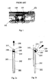
- Fig. 1 a prior art mobile phone 101.
- the mobile phone 101 has two main parts, a main body part 102 and a sliding cover part 103, which are connected together with a sliding connection.
- the main body part 102 includes among other components a camera module 104 and the sliding cover part 103 includes among other components a display module 105.
- the camera module 104 can normally be operated in both cover part 103 positions meaning that the sliding cover part 103 can be either open or closed. With this arrangement the user can for example choose between portrait or landscape mode for the camera depending on the manufacturer's design.
- Figs. 2 a-b is presented an electronic communication device 201 according to the first embodiment of the present invention having a main body part 202 and a sliding cover part 203.
- main body part 202 of the electronic communication device 201 is connected with a hinge 205 .
- a dynamic multifunctional module 206 is joined from one edge to the main body part with an articulation or with articulation means.
- This dynamic multifunctional module 206 includes a camera module (image capturing device) and can include also for example an antenna and several audio components (not shown in Figs. 2 a-b).
- the lens 207 of the camera (and at the same time the picture taking direction) is oriented to the direction of an arrow 208 in Fig. 2 a (first position).
- the lens 207 of the camera is oriented to the direction of an arrow 209 (second position).
- the camera can be operated in both first and second positions.
- the advantage of this arrangement is that the camera module can be turned 90 degrees compared to the prior art mobile phone in Fig. 1 when the sliding cover part 203 is closed (Fig. 2 a).
- This makes it possible to manufacture of a slimmer electronic communication device 201 with a prior art type camera module because the thickness of the camera module in the picture taking direction is not restricting the thickness of the whole electronic communication device.
- having the camera in the length of the electronic communication device also gives the possibility to have camera with an optical zoom without increasing the width or the thickness of the electronic communication device. The length is inevitably increased but that is not so critical a dimension.
- the dynamic multifunctional module 206 When the sliding cover part 203 slides out it turns at the same time the dynamic multifunctional module 206 from the first position (Fig. 2 a) to the second position (Fig. 2b). It thus comprises means for changing the direction of the module in relation to the main body part 202.
- the turning is arranged around the hinge 205 which is situated at the top and outer corner 210 of the main body part 202. In this second position of the Fig. 2 b the orientation of the camera module (and at the same time the whole dynamic multifunctional module 206) can be turned even over 90 degrees, if necessary.
- the turning angle 211 In the solution presented in Figs. 2 a-b the turning angle 211 is about 45 degrees from first position (Fig. 2a) to the second position (Fig. 2b).
- the turning angle 211 can be adjusted by arranging different sized projections to the adjacent corner 212 of the hinge 205 of the dynamic multifunctional module 206 (not shown in Figs. 2a-b).
- the camera module is situated to the thicker part (the far end part) 312 of the dynamic multifunctional module 306.
- the lens 307 of the camera (and picture taking direction) is oriented to the direction of an arrow 308 in Fig. 3 a (first position).
- the lens 307 of the camera is oriented to the direction of an arrow 309 (second position).
- the camera can be operated in both positions.
- the turning angle 311 of the camera is only few degrees but this arrangement makes it possibly to make slimmer electronic communication device than prior art slider phones.
- Fig. 4 is presented more specifically the arrangement of the first embodiment of the invention.
- the drawing is done in a partly transparent way so that the parts inside the dynamic multifunctional module 406 can be seen better.
- the dynamic multifunctional module 406 is in a tilted position related to the device's main body part 402 and the sliding cover part 403 extends over the dynamic multifunctional module 406.
- the sliding cover part 403 has guideways 413 at both sides of the sliding cover part.
- the hinge 405 can be clearly seen in the front corner 410 of the dynamic multifunctional module 406.
- the camera module 404 is situated in the middle of the dynamic multifunctional module 406. On both sides of the camera module 404 there are speakers 414, audio chambers 415 and speaker grills 416.
- Fig. 5 is presented more specifically the arrangement of the second embodiment of the invention.
- the drawing is done in a partly transparent way so that the parts inside the dynamic multifunctional module 506 can be seen better.
- the dynamic multifunctional module 506 is in a tilted position related to the device's main body part 502 and the sliding cover part 503 extends over the dynamic multifunctional module 506.
- the sliding cover part 503 has guideways 513 at both sides of the sliding cover part.
- the hinge 505 can be clearly seen in the front corner 510 of the dynamic multifunctional module 506.
- the camera module 504 is situated in the middle of the dynamic multifunctional module 506. On both sides of the camera module 504 there are speakers 514, audio chambers 515 and speaker grills 516. Also an antenna radiator 517 is situated in the dynamic multifunctional module 506.
- One of the advantages of this invention is that the camera increases available space for an audio chamber and an antenna reflector.
- the invention also includes a method for changing an image capturing direction of an electronic communication device presented for example in Figs. 2 a-b and 3 a-b, where a sliding body part 203 is moving in relation to main body part 202 along guideways for opening the electronic communication device 201 and at the same time the sliding body part is turning a dynamic multifunctional module 206, which dynamic multifunctional module is connected from one edge 210 to the main body part with an articulation and linked to sliding body part, from the first image capturing direction 208 to the second image capturing direction 209 around the articulation 205.
- a nail and a screw may not be structural equivalents in that a nail employs a cylindrical surface to secure wooden parts together, whereas a screw employs a helical surface, in the environment of fastening wooden parts, a nail and a screw may be equivalent structures.
Landscapes
- Engineering & Computer Science (AREA)
- Signal Processing (AREA)
- Computer Networks & Wireless Communication (AREA)
- Telephone Set Structure (AREA)
Applications Claiming Priority (1)
| Application Number | Priority Date | Filing Date | Title |
|---|---|---|---|
| US11/424,276 US20070291534A1 (en) | 2006-06-15 | 2006-06-15 | An Electronic Communication Device with a Dynamic Multifunctional Module |
Publications (1)
| Publication Number | Publication Date |
|---|---|
| EP1868356A1 true EP1868356A1 (de) | 2007-12-19 |
Family
ID=38564336
Family Applications (1)
| Application Number | Title | Priority Date | Filing Date |
|---|---|---|---|
| EP07109163A Withdrawn EP1868356A1 (de) | 2006-06-15 | 2007-05-30 | Elektronische Kommunikationsvorrichtung mit dynamischem Multifunktionsmodul |
Country Status (4)
| Country | Link |
|---|---|
| US (1) | US20070291534A1 (de) |
| EP (1) | EP1868356A1 (de) |
| KR (1) | KR100880728B1 (de) |
| CN (1) | CN101102346A (de) |
Families Citing this family (2)
| Publication number | Priority date | Publication date | Assignee | Title |
|---|---|---|---|---|
| TWI386008B (zh) * | 2008-01-22 | 2013-02-11 | Asustek Comp Inc | 可攜式電子裝置 |
| US7992773B1 (en) * | 2010-09-15 | 2011-08-09 | Reagan Inventions, Llc | System and method for presenting information about an object on a portable electronic device |
Citations (6)
| Publication number | Priority date | Publication date | Assignee | Title |
|---|---|---|---|---|
| US5748441A (en) * | 1995-06-22 | 1998-05-05 | Siemens Aktiengesellschaft | Notepad computer having an integrated video camera |
| US20030109232A1 (en) * | 2001-12-08 | 2003-06-12 | Samsung Electronics Co., Ltd. | Camera lens mounting device of folder type telephone |
| US20050007445A1 (en) * | 2003-07-11 | 2005-01-13 | Foote Jonathan T. | Telepresence system and method for video teleconferencing |
| US20050049019A1 (en) * | 2003-08-27 | 2005-03-03 | Byoung-Gon Lee | Sliding-type mobile communication terminal having camera interlocking device |
| EP1551157A1 (de) * | 2004-01-02 | 2005-07-06 | SK Teletech Co., Ltd. | Verschiebbares mobiles Kommunikationsendgerät mit drehbarer Kamera |
| EP1553749A1 (de) * | 2004-01-09 | 2005-07-13 | SK Teletech Co., Ltd. | Schiebendes bewegliches Telefon mit Kamera |
Family Cites Families (6)
| Publication number | Priority date | Publication date | Assignee | Title |
|---|---|---|---|---|
| GB2368992B (en) * | 2000-11-10 | 2005-03-30 | Nokia Mobile Phones Ltd | Mobile Imaging |
| US7106357B2 (en) * | 2001-08-27 | 2006-09-12 | Olympus Optical Co., Ltd. | Portable information terminal device having camera feature |
| KR100543701B1 (ko) * | 2003-06-17 | 2006-01-20 | 삼성전자주식회사 | 공간형 입력 장치 및 방법 |
| KR100630098B1 (ko) * | 2004-02-20 | 2006-09-27 | 삼성전자주식회사 | 휴대용 디지털 통신 장치 |
| KR20050112737A (ko) * | 2004-05-28 | 2005-12-01 | 주식회사 팬택 | 회전형 카메라모듈을 구비한 슬라이딩형 이동통신 단말기 |
| KR20060035478A (ko) * | 2004-10-22 | 2006-04-26 | 엘지전자 주식회사 | 슬라이딩형 휴대 단말기 |
-
2006
- 2006-06-15 US US11/424,276 patent/US20070291534A1/en not_active Abandoned
-
2007
- 2007-05-30 EP EP07109163A patent/EP1868356A1/de not_active Withdrawn
- 2007-06-14 CN CNA2007101091578A patent/CN101102346A/zh active Pending
- 2007-06-14 KR KR1020070058499A patent/KR100880728B1/ko not_active Expired - Fee Related
Patent Citations (6)
| Publication number | Priority date | Publication date | Assignee | Title |
|---|---|---|---|---|
| US5748441A (en) * | 1995-06-22 | 1998-05-05 | Siemens Aktiengesellschaft | Notepad computer having an integrated video camera |
| US20030109232A1 (en) * | 2001-12-08 | 2003-06-12 | Samsung Electronics Co., Ltd. | Camera lens mounting device of folder type telephone |
| US20050007445A1 (en) * | 2003-07-11 | 2005-01-13 | Foote Jonathan T. | Telepresence system and method for video teleconferencing |
| US20050049019A1 (en) * | 2003-08-27 | 2005-03-03 | Byoung-Gon Lee | Sliding-type mobile communication terminal having camera interlocking device |
| EP1551157A1 (de) * | 2004-01-02 | 2005-07-06 | SK Teletech Co., Ltd. | Verschiebbares mobiles Kommunikationsendgerät mit drehbarer Kamera |
| EP1553749A1 (de) * | 2004-01-09 | 2005-07-13 | SK Teletech Co., Ltd. | Schiebendes bewegliches Telefon mit Kamera |
Also Published As
| Publication number | Publication date |
|---|---|
| CN101102346A (zh) | 2008-01-09 |
| KR100880728B1 (ko) | 2009-02-02 |
| US20070291534A1 (en) | 2007-12-20 |
| KR20070119562A (ko) | 2007-12-20 |
Similar Documents
| Publication | Publication Date | Title |
|---|---|---|
| EP2237532B1 (de) | Tragbares Informationsendgerät | |
| US7869840B2 (en) | Semi-automatic swing device for swing-type portable terminal | |
| US20040203535A1 (en) | Mobile phone having a rotational camera lens housing | |
| US20070082718A1 (en) | Curved sliding-type portable communication apparatus and sliding device thereof | |
| EP1538814A1 (de) | Verschiebbare, aufklappbare, tragbare digitale Vorrichtung | |
| CN1802078A (zh) | 滑动型便携式终端的半自动滑动装置 | |
| US20060197863A1 (en) | Apparatus for rotating camera lens module for mobile terminal | |
| CN100534109C (zh) | 使用柔性材料的滑动型便携式终端 | |
| CN1461168A (zh) | 折叠式便携通信终端 | |
| KR20040077522A (ko) | 폴더형 카메라장치 및 폴더형 휴대전화기 | |
| US20060088310A1 (en) | Camera rotating apparatus of portable terminal | |
| JP2007096542A (ja) | プロジェクタ機能付携帯端末 | |
| JP2008507936A (ja) | 光学ズーム機能が可能な携帯用端末器カメラモジュール | |
| US20050264984A1 (en) | Sliding-type portable communication device having dual liquid crystal display | |
| CN1848861A (zh) | 具有滑动显示单元的折叠型便携式通信装置 | |
| KR101139074B1 (ko) | 피봇식 힌지 기구를 구비한 휴대용 전자 장치 | |
| CN1881065A (zh) | 用于便携式终端的照相机镜头组件 | |
| EP1868356A1 (de) | Elektronische Kommunikationsvorrichtung mit dynamischem Multifunktionsmodul | |
| US8607415B2 (en) | Hinge apparatus for a foldable electronic device | |
| JP2005277775A (ja) | 折り畳み式携帯通信端末 | |
| JP4604548B2 (ja) | 携帯端末 | |
| KR100557067B1 (ko) | 수직 방향 사이드 가이드 레일을 이용한 슬라이딩-업 타입휴대용 디지털 통신 장치 | |
| KR20040102483A (ko) | 폴더형 휴대폰의 카메라 도어 개폐장치 | |
| JP2007074583A (ja) | 撮像機能付き携帯電子機器 | |
| KR20050011236A (ko) | 휴대용 단말기의 카메라 자동 개폐 장치 |
Legal Events
| Date | Code | Title | Description |
|---|---|---|---|
| PUAI | Public reference made under article 153(3) epc to a published international application that has entered the european phase |
Free format text: ORIGINAL CODE: 0009012 |
|
| AK | Designated contracting states |
Kind code of ref document: A1 Designated state(s): AT BE BG CH CY CZ DE DK EE ES FI FR GB GR HU IE IS IT LI LT LU LV MC MT NL PL PT RO SE SI SK TR |
|
| AX | Request for extension of the european patent |
Extension state: AL BA HR MK YU |
|
| 17P | Request for examination filed |
Effective date: 20080221 |
|
| 17Q | First examination report despatched |
Effective date: 20080320 |
|
| AKX | Designation fees paid |
Designated state(s): AT BE BG CH CY CZ DE DK EE ES FI FR GB GR HU IE IS IT LI LT LU LV MC MT NL PL PT RO SE SI SK TR |
|
| STAA | Information on the status of an ep patent application or granted ep patent |
Free format text: STATUS: THE APPLICATION IS DEEMED TO BE WITHDRAWN |
|
| 18D | Application deemed to be withdrawn |
Effective date: 20101109 |