EP1868496B1 - Vorrichtung zum einsatz und zur fixierung eines sensors - Google Patents
Vorrichtung zum einsatz und zur fixierung eines sensors Download PDFInfo
- Publication number
- EP1868496B1 EP1868496B1 EP06737153.4A EP06737153A EP1868496B1 EP 1868496 B1 EP1868496 B1 EP 1868496B1 EP 06737153 A EP06737153 A EP 06737153A EP 1868496 B1 EP1868496 B1 EP 1868496B1
- Authority
- EP
- European Patent Office
- Prior art keywords
- implant assembly
- wire
- vessel
- anchor
- secondary lumen
- Prior art date
- Legal status (The legal status is an assumption and is not a legal conclusion. Google has not performed a legal analysis and makes no representation as to the accuracy of the status listed.)
- Expired - Lifetime
Links
Images


Classifications
-
- A—HUMAN NECESSITIES
- A61—MEDICAL OR VETERINARY SCIENCE; HYGIENE
- A61B—DIAGNOSIS; SURGERY; IDENTIFICATION
- A61B5/00—Measuring for diagnostic purposes; Identification of persons
- A61B5/02—Detecting, measuring or recording for evaluating the cardiovascular system, e.g. pulse, heart rate, blood pressure or blood flow
- A61B5/021—Measuring pressure in heart or blood vessels
- A61B5/0215—Measuring pressure in heart or blood vessels by means inserted into the body
-
- A—HUMAN NECESSITIES
- A61—MEDICAL OR VETERINARY SCIENCE; HYGIENE
- A61B—DIAGNOSIS; SURGERY; IDENTIFICATION
- A61B5/00—Measuring for diagnostic purposes; Identification of persons
- A61B5/03—Measuring fluid pressure within the body other than blood pressure, e.g. cerebral pressure ; Measuring pressure in body tissues or organs
-
- A—HUMAN NECESSITIES
- A61—MEDICAL OR VETERINARY SCIENCE; HYGIENE
- A61B—DIAGNOSIS; SURGERY; IDENTIFICATION
- A61B5/00—Measuring for diagnostic purposes; Identification of persons
- A61B5/68—Arrangements of detecting, measuring or recording means, e.g. sensors, in relation to patient
- A61B5/6846—Arrangements of detecting, measuring or recording means, e.g. sensors, in relation to patient specially adapted to be brought in contact with an internal body part, i.e. invasive
- A61B5/6879—Means for maintaining contact with the body
- A61B5/6882—Anchoring means
-
- A—HUMAN NECESSITIES
- A61—MEDICAL OR VETERINARY SCIENCE; HYGIENE
- A61F—FILTERS IMPLANTABLE INTO BLOOD VESSELS; PROSTHESES; DEVICES PROVIDING PATENCY TO, OR PREVENTING COLLAPSING OF, TUBULAR STRUCTURES OF THE BODY, e.g. STENTS; ORTHOPAEDIC, NURSING OR CONTRACEPTIVE DEVICES; FOMENTATION; TREATMENT OR PROTECTION OF EYES OR EARS; BANDAGES, DRESSINGS OR ABSORBENT PADS; FIRST-AID KITS
- A61F2/00—Filters implantable into blood vessels; Prostheses, i.e. artificial substitutes or replacements for parts of the body; Appliances for connecting them with the body; Devices providing patency to, or preventing collapsing of, tubular structures of the body, e.g. stents
- A61F2/82—Devices providing patency to, or preventing collapsing of, tubular structures of the body, e.g. stents
-
- A—HUMAN NECESSITIES
- A61—MEDICAL OR VETERINARY SCIENCE; HYGIENE
- A61F—FILTERS IMPLANTABLE INTO BLOOD VESSELS; PROSTHESES; DEVICES PROVIDING PATENCY TO, OR PREVENTING COLLAPSING OF, TUBULAR STRUCTURES OF THE BODY, e.g. STENTS; ORTHOPAEDIC, NURSING OR CONTRACEPTIVE DEVICES; FOMENTATION; TREATMENT OR PROTECTION OF EYES OR EARS; BANDAGES, DRESSINGS OR ABSORBENT PADS; FIRST-AID KITS
- A61F2/00—Filters implantable into blood vessels; Prostheses, i.e. artificial substitutes or replacements for parts of the body; Appliances for connecting them with the body; Devices providing patency to, or preventing collapsing of, tubular structures of the body, e.g. stents
- A61F2/95—Instruments specially adapted for placement or removal of stents or stent-grafts
-
- A—HUMAN NECESSITIES
- A61—MEDICAL OR VETERINARY SCIENCE; HYGIENE
- A61B—DIAGNOSIS; SURGERY; IDENTIFICATION
- A61B5/00—Measuring for diagnostic purposes; Identification of persons
- A61B5/0002—Remote monitoring of patients using telemetry, e.g. transmission of vital signals via a communication network
- A61B5/0031—Implanted circuitry
-
- A—HUMAN NECESSITIES
- A61—MEDICAL OR VETERINARY SCIENCE; HYGIENE
- A61B—DIAGNOSIS; SURGERY; IDENTIFICATION
- A61B5/00—Measuring for diagnostic purposes; Identification of persons
- A61B5/07—Endoradiosondes
- A61B5/076—Permanent implantation
-
- A—HUMAN NECESSITIES
- A61—MEDICAL OR VETERINARY SCIENCE; HYGIENE
- A61F—FILTERS IMPLANTABLE INTO BLOOD VESSELS; PROSTHESES; DEVICES PROVIDING PATENCY TO, OR PREVENTING COLLAPSING OF, TUBULAR STRUCTURES OF THE BODY, e.g. STENTS; ORTHOPAEDIC, NURSING OR CONTRACEPTIVE DEVICES; FOMENTATION; TREATMENT OR PROTECTION OF EYES OR EARS; BANDAGES, DRESSINGS OR ABSORBENT PADS; FIRST-AID KITS
- A61F2/00—Filters implantable into blood vessels; Prostheses, i.e. artificial substitutes or replacements for parts of the body; Appliances for connecting them with the body; Devices providing patency to, or preventing collapsing of, tubular structures of the body, e.g. stents
- A61F2/82—Devices providing patency to, or preventing collapsing of, tubular structures of the body, e.g. stents
- A61F2/848—Devices providing patency to, or preventing collapsing of, tubular structures of the body, e.g. stents having means for fixation to the vessel wall, e.g. barbs
-
- A—HUMAN NECESSITIES
- A61—MEDICAL OR VETERINARY SCIENCE; HYGIENE
- A61F—FILTERS IMPLANTABLE INTO BLOOD VESSELS; PROSTHESES; DEVICES PROVIDING PATENCY TO, OR PREVENTING COLLAPSING OF, TUBULAR STRUCTURES OF THE BODY, e.g. STENTS; ORTHOPAEDIC, NURSING OR CONTRACEPTIVE DEVICES; FOMENTATION; TREATMENT OR PROTECTION OF EYES OR EARS; BANDAGES, DRESSINGS OR ABSORBENT PADS; FIRST-AID KITS
- A61F2/00—Filters implantable into blood vessels; Prostheses, i.e. artificial substitutes or replacements for parts of the body; Appliances for connecting them with the body; Devices providing patency to, or preventing collapsing of, tubular structures of the body, e.g. stents
- A61F2/95—Instruments specially adapted for placement or removal of stents or stent-grafts
- A61F2/9522—Means for mounting a stent or stent-graft onto or into a placement instrument
-
- A—HUMAN NECESSITIES
- A61—MEDICAL OR VETERINARY SCIENCE; HYGIENE
- A61F—FILTERS IMPLANTABLE INTO BLOOD VESSELS; PROSTHESES; DEVICES PROVIDING PATENCY TO, OR PREVENTING COLLAPSING OF, TUBULAR STRUCTURES OF THE BODY, e.g. STENTS; ORTHOPAEDIC, NURSING OR CONTRACEPTIVE DEVICES; FOMENTATION; TREATMENT OR PROTECTION OF EYES OR EARS; BANDAGES, DRESSINGS OR ABSORBENT PADS; FIRST-AID KITS
- A61F2/00—Filters implantable into blood vessels; Prostheses, i.e. artificial substitutes or replacements for parts of the body; Appliances for connecting them with the body; Devices providing patency to, or preventing collapsing of, tubular structures of the body, e.g. stents
- A61F2/95—Instruments specially adapted for placement or removal of stents or stent-grafts
- A61F2002/9505—Instruments specially adapted for placement or removal of stents or stent-grafts having retaining means other than an outer sleeve, e.g. male-female connector between stent and instrument
- A61F2002/9511—Instruments specially adapted for placement or removal of stents or stent-grafts having retaining means other than an outer sleeve, e.g. male-female connector between stent and instrument the retaining means being filaments or wires
-
- A—HUMAN NECESSITIES
- A61—MEDICAL OR VETERINARY SCIENCE; HYGIENE
- A61F—FILTERS IMPLANTABLE INTO BLOOD VESSELS; PROSTHESES; DEVICES PROVIDING PATENCY TO, OR PREVENTING COLLAPSING OF, TUBULAR STRUCTURES OF THE BODY, e.g. STENTS; ORTHOPAEDIC, NURSING OR CONTRACEPTIVE DEVICES; FOMENTATION; TREATMENT OR PROTECTION OF EYES OR EARS; BANDAGES, DRESSINGS OR ABSORBENT PADS; FIRST-AID KITS
- A61F2250/00—Special features of prostheses classified in groups A61F2/00 - A61F2/26 or A61F2/82 or A61F9/00 or A61F11/00 or subgroups thereof
- A61F2250/0001—Means for transferring electromagnetic energy to implants
- A61F2250/0002—Means for transferring electromagnetic energy to implants for data transfer
Definitions
- This invention relates generally to implantation of intracorporeal devices into vessels, and to fixing the devices, either permanently or temporarily, within the vessel.
- the fixation device should be passive and maintain a separation distance between the sensor and the vessel wall to maintain blood flow past the sensor.
- the deployed size and radial strength of the device should be sufficient to prevent its migration into vessels that would be occluded by the dimensions of the sensor while creating minimal stress concentrations where the fixation device contacts the vessel wall.
- intracorporeal devices can be designed sufficiently small in size so that when deployed in organs or regions with sufficiently redundant blood flow, the device can embolize on its own without harming the organ or the host.
- the fixation device should be sufficiently versatile as not to depend, within physiologically relevant ranges, on the size of the vessel in order to maintain its position.
- Prior art devices include a self-expansible stent on which an intracorporeal device is mounted. This stent maintains a known length when implanted in a vessel where only the approximate diameter can be determined.
- Other devices and methods include fixation of a sensor in a bodily lumen, in which the sensor support is coupled to a fixation device.
- the fixation device is a stent or ring, has a sensor support coupled thereto and is intended to be sutured to the vessel wall or held in place by plastically deforming the structure using a balloon catheter.
- the ring is essentially a stent with an abbreviated length and suffers from the same shortcomings as traditional stent devices.
- a stent is designed with mechanical characteristics that enable it to hold open diseased vessels post dilation. Therefore, the radial strength of the stent is greater than the inward radial forces exerted during vessel recoil. This primary requirement leads to a mismatch in compliance, with that of the stent dominating. Subsequently, stress concentrations are created at the interface of the stent and vessel. These stress concentrations are greatest at the terminal ends of the stent where there is an abrupt transition in stiffness between the stented and unstented segments of the vessel. Because undiseased vessels are usually more compliant compared to diseased ones, this compliance mismatch is amplified when placing a stent in healthy vasculature.
- International application WO 00/74557 A discloses an implantable device with legs contacting the vessel walls which can travel downstream to lodge at a vessel branch, and does not disclose a wire member having a double-loop configuration capable of stabilizing the intracorporeal device body from tumbling end-over-end within a vessel.
- US application US 2002/151816 A1 discloses a sensing device that is implanted into the vessel to its deployment site by a stent-like spring cage or spring arms.
- the implant assembly can be inserted into a blood vessel. It is disclosed that after insertion into the vessel, the spring cage expands and lodges the implant assembly at the sensing location, while allowing blood (or other fluid) to continue flowing past the implant assembly. From this description, it is clear that the implant assembly is not capable of travelling in the vessel. Upon insertion, the implant device lodges immediately. The same applies to another endoluminal attachment scheme disclosed.
- the devices disclosed are designed to be fixed at the location of deployment.
- US application US 2003/125790 A1 discloses a deployment device for deploying a self-expandable medical implant at a target location in a body cavity.
- the deployment device is proposed to be suitable for precise and well-controlled manner of deployment, so as to minimize damage to the cavity wall and to position the implant accurately at the target location.
- the device relates to systems in which accurate location is required and the implants are deployed at that location.
- European application EP 1 264 572 A1 discloses an implantable medical device comprising a housing having a proximal end and a distal end and having a longitudinal axis; a first set of anchoring members operatively connected to the proximal end of the housing; a second set of anchoring members operatively connected to the distal end of the housing; the first set of anchoring members and the second set of anchoring members being movable between a collapsed position and a deployed position, the collapsed position being defined as a position whereby the first set of anchoring members and the second set of anchoring members are substantially parallel to the longitudinal axis of the housing and the deployed position being defined as a position whereby the first set of anchoring members and the second set of anchoring members are substantially perpendicular to the longitudinal axis of the housing, and wherein each anchoring member of the first set of anchoring members and the second set of anchoring members comprise a ring member, each ring member having a tissue engaging surface thereon.
- US application US 2004/176672 A1 discloses a sensor for implantation within a blood vessel, comprising a support, having a first side for contacting the wall of the vessel and a second side for facing radially inwardly toward the center of the vessel; and a sensor carried by the support and having a sensing surface thereon; wherein the sensing surface is spaced radially inwardly from the first side and wherein the sensing surface includes a layer that minimizes the formation of thrombus.
- US patent 6,416,474 discloses a biosensor for monitoring pressure or other physical parameters at an aneurysm site. It is mountable to a tubular prosthesis that is expandable between contracted and enlarged conditions. A loop, having the biosensor attached thereto, is securable around the prosthesis. An apparatus is used to deliver the loop to an aneurysm site that includes a catheter having a connector on its distal end for detachably securing the loop thereto. The prosthesis is advanced in a contracted state to the aneurysm, and the apparatus, with the loop connected thereto, is advanced to the aneurysm site. The loop and the prosthesis are positioned coaxially with respect to one another, and the prosthesis is expanded towards its enlarged condition, thereby engaging the loop around the prosthesis and engaging the prosthesis with a wall of the blood vessel at the treatment site.
- the present invention is concerned with an implant assembly as defined in independent claim 1 and the dependent claims 2-8 and a delivery system for deployment and fixation of the implant assembly in a human body as defined in claim 9.
- the invention is concerned with an implant assembly adapted for being released into a vessel at a location having a diameter D1 and capable of travelling in the vessel and capable of lodging in the vessel at a location having a diameter D2, the implant assembly comprising:
- the implant assembly of the present invention is characterized in that the intracorporeal device further comprises a coating.
- the ends of the wire member are inserted under the coating of the device to attach the wire to the device.
- the implant assembly has a diameter less than D 1 but greater than or equal to D2 and an overall length that is at least two times the diameter D2, and the wire member has a double-loop configuration capable of stabilizing the intracorporeal device body from tumbling end-over-end within a vessel.
- Another aspect of the present invention is concerned with a delivery system for deployment and fixation of an implant assembly in a human body, the system comprising:
- a further aspect of this invention is to provide an implant assembly adapted to be delivered via a delivery apparatus, such as a catheter.
- An implant assembly of this invention includes an intracorporeal device and an anchoring structure used to stabilize the intracorporeal device in the body, such as in a vessel.
- Delivery systems of this invention are used to deploy and secure the implant assembly in a desired location in a vessel and include a delivery apparatus and an implant assembly.
- the intracorporeal device may be a pressure sensor, further described below.
- the anchoring structure may be a structure capable of being introduced into the body via a delivery apparatus, such as a catheter, and then lodging within the vessel.
- Anchoring structures disclosed in the description may include structure including opposed wire loops, radial wire array structures, and daisy petal structures, all further described below.
- All of the implant assemblies of this invention obstruct approximately 50% or less of the cross-sectional area of the vessel in which it resides. Preferably, the implant assemblies obstruct 20% or less of the cross-sectional area of the vessel. Minimizing the obstruction of flow within the vessel allows the intracorporeal device to remain secured in position in a vessel without creating significant impact to the flow within the vessel. Furthermore, all of the implant assemblies disclosed herein rely on the physical size of the expanded anchoring structure coupled with the stiffness of the wire used to construct the anchoring structure to prevent further distal movement. This is contrary to stent or vena cava filter type mechanisms wherein fixation is achieved by radially exerted force and/or hook or barb attachment features.
- Anchoring structures of this invention may be formed from metal or polymer and are in the form of a wire structure as defined in the claims.
- the wire diameter of the anchoring structures of the current invention lies in the range of about 0.00254 cm to about 0.0381 cm (0.001 to about 0.015 inches).
- the material comprising the wire can be any biocompatible material known in the art that possess sufficient elastic properties to be useful for the purpose at hand.
- the material comprising the wire is a polymer.
- the material comprising the wire may be a metal, such as nitinol, stainless steel, eligiloy, cobalt chrome alloys, or any other suitable metal.
- the biocompatible wire is coated with a dielectric material, such as, but not limited to, PTFE, polyurethane, parylene and diamond-like carbon (DLC) so as not to pose electromagnetic interference with the function of the intracorporeal device when the device comprises an RF sensor.
- a dielectric material such as, but not limited to, PTFE, polyurethane, parylene and diamond-like carbon (DLC)
- intracorporeal device includes any and all implantable devices. Such devices can include, e.g., sensors that measure chemical and/or physical parameters, devices configured to perform a function, e.g. drug delivery devices, and combinations of the same.
- the intracorporeal device may communicate with external electronics either wirelessly or by being placed in physical contact with said electronics, such as by a wire.
- the exemplary device disclosed herein describes a coating as a feature. It should be understood that this invention encompasses an intracorporeal device constructed of a polymeric material and that the same construction techniques used to create the anchoring structures could be employed by threading the wires directly through the polymeric material comprising the device. Additionally, materials used in the construction of such intracorporeal devices, coatings or otherwise, could be any biocompatible polymer. Such materials include but are not limited to biocompatible silicone rubber, FEP, PTFE, urethane, PVC, nylon, and polyethylene.
- the intracorporeal device used to couple to the anchoring structures described below has a width of about 0.5 to about 4 mm, a height of about 0.5 to about 4 mm, and a length of about 0.5 to about 12 mm. In one embodiment, the intracorporeal device has a width of 3.2 mm, a height of 2 mm, and a length of 10 mm.
- the implant assembly of this invention adapted for deployment and fixation within a vessel includes an intracorporeal device and a wire structure having wire loops.
- the loops may traverse the length of the device or may be limited to one end of the device.
- an implant assembly 30 having a double loop structure 32 includes a wire 34 attached to an intracorporeal device 36 at an attachment site (not shown).
- the wire 34 is threaded through an end of the intracorporeal device 36 at a hole 38.
- the anchor point is formed by crimping a piece of metal to the wire and trimming off the excess wire, so that the crimped-on metal comprises the terminal end of the wire. This metal end also provides a radiopaque marker for fluoroscopic visualization of the device.
- the wire 34 is threaded through the hole 38 on one end of the device, the wire is pulled with sufficient force to bury the anchor fixedly into the coating of the intracorporeal device.
- the wire 34 is then looped around to form the double loop configuration 32.
- the second free end is also inserted under the coating and the anchor is buried in the coating to fix the anchor. In this manner, the ends of the wire are inserted under the coating of the intracorporeal device 36.
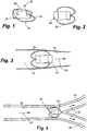
- Figure 3 illustrates the deployment of the implant assembly 30 within a narrowing vessel.
- the arrow 39 shown in Figure 3 indicates the direction of blood flow.
- the wire loop 34 will contact the inner surface 40 of the wall of the vessel 42.
- this contact may occur immediately upon deployment.
- the implant assembly can be configured so that the wire 34 of the implant assembly 30 does not initially contact the inner surface 40 of the vessel 42 but instead travels down the narrowing vessel until, at some point, the vessel narrows to such an extent that the wire loop 34 makes contact with the inner surface 40 of the vessel 42.
- the wire structure may compress radially inward or bow backwards as an interference fit is created. Or, depending upon the compliance of the wire comprising the implant assembly, the anchor structure 42 may yield, permitting the implant assembly 30 to travel further downstream. The implant assembly 30 will ultimately reach a point in the narrowing vessel 42 at which an interference fit between the wire loop 34 and the vessel will cause the implant assembly to lodge and to be held in place against any further movement.
- An alternate exemplary method of anchoring an implant assembly 30 is based upon the principle of causing the intracorporeal device to lodge at a furcation in a vessel of a patient.
- the pulmonary artery which originates in the right ventricle, divides into the right and left pulmonary artery branches, one directed to each lung. These arteries divide and then subdivide, eventually to send arteries to all of the bronchopulmonary segments that form the different lobes of each lung.
- the pulmonary arterial vessels decrease in diameter significantly each time they divide.
- the implant assembly including the wire loops, can travel down a first vessel with the flow of blood, but when the implant assembly reaches a furcation, the implant assembly is too large to fit through either of the smaller branch vessels.
- the implant assembly thus lodges at the furcation, prevented from moving downstream by being too large and not sufficiently compliant to fit into the branch vessels, and prevented from moving upstream by the flow of blood through the arteries.
- the implant assembly diameter is equal to or greater than the inner diameter of the first vessel. In this case, the implant assembly is sufficiently compliant so it does not produce an interference fit as it travels down the vessel but does preserve the intended orientation of the implant assembly when it reaches the subsequent furcation.
- the implant assembly diameter is less than the inner diameter of the arterial vessel such that no particular orientation is actively preserved but the implant assembly is too large and stiff to fit through subsequent branch vessels.
- the implant assembly is configured such that, after a short period of time, e.g. 30 days, the deployment position is further reinforced by tissue overgrowth of the wire loops where they contact the vessel wall. At this point, the dominant fixation mechanism is the tissue to wire connection and the implant assembly cannot be easily removed without risk of damaging the vessel.
- the implant assembly 30 has been released into a first vessel 49.
- the implant assembly is free to travel through the first vessel 49 with the flow of blood in the direction indicated by the arrows 51.
- the first vessel 49 divides into smaller vessels 55, 56. Because the implant assembly 30 is substantially larger than the cross-section of any of the smaller vessels 55, 56, the implant assembly cannot proceed any further and lodges at the furcation 53.
- a loop structure has a "figure eight" shape.
- An implant assembly 31, according to the present invention, having a double loop structure 33 includes a wire 35 attached to the intracorporeal device body 37 at an attachment site (not shown). The ends of the wire 35 are inserted under the coating of the intracorporeal device body 37 as described in the previous example.
- the purpose of the "figure eight" or double loop structure 33 is to stabilize the intracorporeal device body from rotating or tumbling end-over-end within the vessel, thereby assuring that, in the case of a wireless sensing element comprising the intracorporeal device, a coupling element of the intracorporeal device body remains properly oriented with respect to optimal angles of interrogation via extracorporeal communication and data acquisition devices.
- the "figure eight" or double loop structure 33 of the disclosed embodiment measures approximately five centimeters in length. However, it will be appreciated that the preferred dimensions depend upon the inner diameter of the vessel into which it is being placed within relatively wide tolerances, and that the dimensions of the "figure eight" or double-loop structure 33 can be modified to adapt the device to any particular vessel.
- the overall length of the intracorporeal device body plus double-loop structure 33 is at least two times, and preferably at least about five times, the diameter of the vessel.
- the implant assembly 31 upon deployment of the implant assembly 31 according to a first exemplary method, the implant assembly 31 is anchored by an interference fit between the wire 35 and the inner surface 41 of the wall of the vessel 43.
- the arrow 51 indicates the direction of blood flow.
- Figure 7 illustrates an alternate exemplary method of anchoring the implant assembly 31, in which the implant assembly is deployed, e.g., into a first pulmonary arterial vessel 49 having a cross-section on the order of the cross-section of the implant assembly.
- the implant assembly thus travels through the first vessel 49 in the direction of blood flow, indicated by the arrows 51.
- the first vessel 49 divides into smaller vessels 55, 56. Because the cross-section of the implant assembly 31 is substantially larger than the cross-section of either of the smaller vessels 55, 56, and not sufficiently compliant to deform further the implant assembly lodges at the furcation 53.
- the opposed loop structure 33 of the implant assembly 31 is constructed of a single wire.
- the opposed loop structure 33 can be constructed of more than one wire.
- the structure includes a plurality of wire loops 44 encircling an intracorporeal device 46.
- the wire 48 is threaded from end to end in a circular fashion, through one or more holes 50 located on each end of the intracorporeal device, to form the loops.
- the free end of the wire is used to create another anchor as described above.
- the second free end is then pulled back into the coating with sufficient force to bury the second anchor fixedly in the coating.
- the location of the second anchor lies on the opposite side of the intracorporeal device from the first anchor.
- This configuration is useful in order to position anchors away from a sensing or actuating element and/or to provide a means for determining the orientation of the device when viewed via fluoroscopic means.
- the wire loops are then arranged by mechanical means to create wire members that are substantially evenly distributed radially around the longitudinal axis of the intracorporeal device.
- the wire loops may be attached to the intracorporeal device 40 by threading through one hole 50 located near the edge of the device 46 as referenced to the longitudinal axis of the device 46, as shown in Figure 8 .
- the wire loops may be attached to the intracorporeal device 46 by threading through multiple holes 50 located near each edge of the device 46, as shown in Figure 12 .
- the implant assemblies of Figures 8, 9 , 12, and 13 may be deployed according to either of the two exemplary methods described above.
- the implant assemblies can be configured so that they are anchored by an interference fit between the implant assemblies and the walls 52 of the vessel 54, as shown in Figures 10 and 14 and described previously. Or the implant assemblies can be configured so that they are allowed to travel down a vessel and lodge at a furcation as previously described.
- the arrows 51 shown in Figures 10, 11 , 14, and 15 indicate the direction of blood flow.
- an implant assembly 130 comprises a intracorporeal device 131, an elongated " figure 8 " wire loop 132, and a pair of wing-like wire loops 134.
- the wing-like wire loops 134 have a longest dimension in a plane orthogonal to the longitudinal axis of the vessel. This longest dimension is, within wide tolerances, on the order of the vessel inner diameter into which the implant assembly 130 is to be introduced, so as to permit the implant assembly to travel down the blood stream until it lodges at a furcation.
- the " figure 8 " wire loop 132 has a length which is greater than the diameter of the vessel into which the implant assembly 130 is to be introduced so as to prevent the implant assembly from flipping end-to-end within the vessel.
- the length of the " figure 8 " wire loop 132 is at least twice the diameter of the vessel into which the implant assembly 130 is to be introduced, and in the disclosed embodiment the length of the " figure 8 " wire loop 132 is approximately five times the diameter of the vessel. This feature is useful to maintain a desired orientation of the implant assembly 130 with respect to the fluid flow within the vessel.
- the " figure 8 " wire loop lies in a plane, and the wing-like wire loops are oriented substantially perpendicular to the plane defined by the wire loops.
- an implant assembly disclosed in the description includes an intracorporeal device and an anchoring structure having a substantially parabolic-shaped profile, as shown in Figures 16-18 .
- an implant assembly 58 includes an intracorporeal device 60 and a radial wire array 62, which includes wire members 64. Members 62 may be attached to the intracorporeal device 60 at an anchor point, as described below.
- the radial wire array 62 can be attached to the intracorporeal device 60 by threading the wire members 64 through one hole 66 located near the edge of the intracorporeal device 60, as shown in Figure 16 .
- the radial wire array 62 can be attached to the intracorporeal device 60 by threading the wire members 64 through two holes 66 located near the edge of the device 60.
- the wire end is press-fit into a coating covering the surface of the device to secure the end.
- the radial wire array may be formed by crimping a piece of metal at a point substantially midlength of the wire bundle and then threading the wire bundle through a hole near the edge of the intracorporeal device, thus lodging the anchor within the silicone material filling the hole.
- the anchor secures the end of the radial wire between the surface of the device and the coating covering the surface of the device.
- the crimped metal anchor provides a radiopaque marker for fluoroscopic visualization of the device.
- the implant assembly Upon deployment of the implant assembly, the implant assembly can be anchored either by an interference fit between the radial wires and the walls of the vessel, as shown in Figure 17 , or by traveling within a vessel until the implant assembly lodges at a furcation, as shown in Figure 18 .
- the radial wire array is self-supporting, as a result of the physical properties of the material.
- the radial wire array may include a mechanical expansion structure to support the array to expand and contact the vessel wall.
- a catheter balloon may be inflated to cause a wire structure to attain and maintain an expanded configuration.
- the intracorporeal device 60 can be positioned outside a radial wire array 62 so that one end 72 of the intracorporeal device 60 is fixed to a point at or near the apex of the radial wire array 62, as shown in Figure 16 .
- the intracorporeal device 60 can also be positioned inside the radial wire array so that one end of the device is fixed to a point at or near the apex of the radial wire array, as shown in Figure 17 .
- the intracorporeal device may have two radial wire arrays 62 attached to the intracorporeal device 60 so that one end of the intracorporeal device is attached to the apex on the exterior of one of the radial wire arrays and the opposing end of said device is attached to the apex on the interior of the second radial wire array, as shown in Figure 18 .
- FIG. 19-24 Another implant assembly disclosed in the description includes an intracorporeal device and an anchoring structure having a daisy petal shape, as shown in Figures 19-24 .
- the implant assembly 76 includes an intracorporeal device 78 and a daisy petal wire structure 80, which contacts the inner surface 82 of the wall of the vessel 84, as shown in Figure 23 .
- the implant assembly of this embodiment can be anchored by an interference fit between the implant assembly and the walls of the vessel.
- the implant assembly can be configured, within wide tolerances, to have a diameter on the order of the vessel inner diameter into which the implant assembly 130 is to be introduced, so as to permit the implant assembly to travel down the blood stream until it lodges at a furcation, as shown in Figure 24 .
- the arrows 51 shown in Figure 24 indicate the direction of blood flow.
- the intracorporeal device has a proximal end 86, a distal end 88, and a longitudinal axis 90 .
- the daisy petal wire structure 80 is positioned so that the structure lies in a plane normal to the longitudinal axis 90 of the intracorporeal device 78.
- the daisy petal wire structure 80 may be constructed of a single wire or of a plurality of wires. As shown in Figure 19 , the daisy petal wire structure 80 includes a plurality of lobes 92. The structure may have either an even or an odd number of lobes.
- the intracorporeal device 78 may have two daisy petal wire structures 80 attached to the device on opposing ends 94, 96 and located along the longitudinal axis 90.
- the daisy petal wire structure 80 may be attached to the intracorporeal device 78 by threading through a single hole 98 located near the edge of the device 78, as shown in Figure 21 .
- the daisy petal wire structure 80 may be attached to the intracorporeal device 78 by threading through two holes 98 located near the edge of the device 78, as shown in Figure 22 .
- the daisy petal wire structure 80 is attached to the intracorporeal device at an anchor point.
- the anchor is made by crimping a piece of metal to the wire and trimming off the excess wire, so that the crimped-on metal comprises the terminal end of the wire.
- This metal end also provides a radiopaque marker for fluoroscopic visualization of the device.
- the wire is threaded through the hole or holes on one end of the intracorporeal device and the wire is pulled with sufficient force to bury the anchor fixedly into the coating.
- the wire is then threaded from top to bottom in a circular fashion, through the hole or holes located on the end of the intracorporeal device, to form the daisy petal structure.
- the free end of the wire is used to create another anchor.
- the second free end is then pulled back into the coating with sufficient force to bury the second anchor fixedly in the coating.
- the wire loops are then arranged by mechanical means to create wire members that are substantially evenly distributed radially around the longitudinal axis of the intracorporeal device.
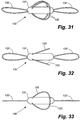
- the delivery apparatus 100 includes a main lumen 102 adapted to accept a core wire 104 ( Figure 27 ) and a secondary lumen comprising a first section 106A and a second section 106B and adapted to accept a tether wire 108 ( Figure 26 ).
- the core wire 104 shown in Figure 27 , provides columnar stiffness to the delivery assembly 100, thereby facilitating advancement of the delivery assembly through the vasculature.
- the core wire 104 also prevents buckling of the delivery assembly 100 when the tether wire is pulled proximally during the implant assembly deployment.
- the core wire 104 has a decreasing diameter toward its distal end 105, providing gradual decrease in stiffness from the proximal to the distal end of the delivery assembly 100.
- the tapered core wire 104 can extend past a guidewire aperture 112 in order to reinforce a potential kink point in the delivery apparatus 100 and to facilitate the advancement of the guidewire into the vasculature.
- the core wire 104 is fixed in the main lumen 102 using adhesive, thermocompression, or any other suitable fixation mechanism. Fixation of the core wire 104 prevents the core wire from being disturbed by the guidewire 110, shown in Figure 28 , when the guidewire 110 enters the main lumen 102 of the delivery apparatus 100 at the guidewire aperture 112 as shown in Figure 29 .
- the tether wire 108 shown in Figure 26 , is slidably positioned within the first secondary lumen portion 106A and exits the first secondary lumen portion at an aperture 114 in the wall of the device. As shown in Figure 29 , the tether wire 108 then passes through the coating of the intracorporeal device 30, exiting on the opposite side of the device. The free end 118 of the tether wire 108 enters the second portion 106B of the secondary lumen at the aperture 109.
- Figure 30 shows an embodiment of a delivery apparatus according to the present invention, adapted to deploy the intracorporeal device 31 of Figures 5-7 . Because of the length of the wire loops 35 of the intracorporeal device 31, the proximal and distal ends of the loops must be secured to the delivery apparatus so that, when the delivery apparatus curves, the loops will follow the curvature of the delivery apparatus. Toward that end, the secondary lumen of the delivery apparatus of Figure 30 is divided into four sections 124A-D. The tether wire 108 exits the first section 124A of the secondary lumen and passes over and through wire loops 55 to attach the implant assembly 51 to the delivery apparatus 100. The tether wire then enters the second portion 124B of the secondary lumen.
- the tether wire then exits the second portion 124B of the secondary lumen and passes through the coating of the intracorporeal device 31.
- the tether wire then enters the third portion 124C of the secondary lumen.
- the tether wire exits the third portion 124C of the secondary lumen, passes over the wire loop 35, and enters the fourth section 124D of the secondary lumen.
- an outer sleeve may be provided to constrain an expansible structure and is slidably positioned over the double lumen tube.
- Deployment and fixation of an implant assembly may be accomplished passively by either an interference fit or lodging at a furcation.
- An implant assembly including an anchoring structure of sufficient size and/or compliance, can be delivered into the vessel and allowed to travel in the blood stream until it lodges at a furcation. After lodging in the vessel, blood flow is maintained due to the configuration of the implant assembly.
- an implant assembly includes an anchoring structure of sufficient compliance that, upon narrowing of the vessel, produces an interference fit thereby preventing substantially any further progress of the device down the vessel.
- the intracorporeal device embolizes without an anchor structure.
- a vessel introducer is positioned in the access site.
- the access site for the vessel introducer may be the right internal jugular vein, the subclavian artery, the right femoral vein, or any other suitable access site.
- a guidewire is placed in the vasculature and positioned across the desired deployment site with the aid of, e.g., a Swan-Ganz catheter, a diagnostic catheter or any other suitable catheter, such catheter being removed after the guidewire is in position.
- the delivery system is loaded into the vessel introducer and navigated to the deployment site.
- the delivery system length can be increased or decreased according to standard practice depending on the access site chosen.
- the deployment site is a vessel, and may be any artery or arteriole in the pulmonary artery vasculature.
- the implant assembly is oriented to a preferred orientation. Then, the implant assembly is deployed by pulling the tether wire proximally to disengage the implant assembly from the delivery apparatus. Upon deployment, the implant assembly is allowed to travel in the vasculature until an interference fit is produced or it lodges at the next furcation in the vasculature, depending on which mode of fixation is intended. The delivery assembly and guidewire are then removed from the body.
- an outer sleeve is provided to constrain an expansible anchor structure so that sliding the outer sleeve proximally allows expansion of the expansible anchor structure.
- the anchor structure is allowed to expand and the implant assembly travels down the vessel until an interference fit is produced or it lodges at the next furcation in the vasculature, depending on which mode of fixation is intended.
- the delivery assembly and guidewire are then removed from the body.
- the exemplary methods described above may be employed with a wireless device, as shown in the Figures, or with a wired intracorporeal device.
- the pulmonary artery is selected as the deployment site for an intracorporeal device.
- considerations relevant to the placement of a pressure sensor are disclosed.
- Other intracorporeal devices could be positioned in alternate locations via modifications to the examples disclosed in this document, such locations and methods being obvious to one skilled in the art in light of the disclosure provided herein.
- To deploy an implant assembly into a pulmonary arterial vessel the right femoral vein is chosen as the access site. The user gains access to the femoral vein via transcutaneous puncture or cut-down. A vessel introducer is placed in the site. A Swan-Ganz or guiding catheter is maneuvered into the pulmonary artery.
- the path to the pulmonary artery is as follows: the femoral vein leads to the inferior vena cava. From the inferior vena cava, the catheter travels through the right atrium to the right ventricle and, finally, to the pulmonary artery. At this point, the right or left branch of the pulmonary artery is selected, and the Swan-Ganz or guiding catheter is positioned in the descending branch of either the right or left pulmonary artery. A guidewire is placed at the deployment site, and the Swan-Ganz or guiding catheter is removed. At this point, the delivery catheter is loaded over the proximal end of the guidewire.
- a guiding catheter can be loaded over the proximal ends of the guidewire and delivery catheter to a point where the distal end of this guiding catheter is located immediately proximal to the implant assembly on the delivery catheter.
- the delivery catheter (and, optionally, guiding catheter) is tracked over the guidewire to the deployment site.
- the tether is pulled proximally to disengage the implant assembly from the delivery apparatus.
- the lung can be divided into three zones depending on the relationship between the pulmonary artery pressure, alveolar pressure, and pulmonary venous pressure.
- Zone 1 the uppermost portion of the lung, the alveolar pressure is greater than that of either the pulmonary artery or the pulmonary vein, causing collapse of the vessel during each respiratory cycle. (Zone 1 conditions do not normally occur in humans.)
- Zone 2 the alveolar pressure is less than the pulmonary artery pressure and greater than the pulmonary venous pressure leading to a state of partial vessel collapse.
- Zone 3 at the bottom of the lungs, all blood vessels remain fully open during the entire respiratory cycle because of the fact that both the pulmonary artery and venous pressures are greater than the alveolar pressure.
- the implant assembly is released into the descending branch of either the right or left pulmonary artery because this will cause the intracorporeal device to lodge in Zone 3 of the lungs. It is not known whether vessel collapse would cause any deleterious effect on the pressure measured by the sensor, but the present invention eliminates this unknown by positioning the sensor in a location where the possibility of this phenomenon is minimized.
- top,” “bottom,” “upper,” “lower,” “left,” “right,” “front,” “back,” “proximal,” “distal,” and the like are used only for convenience of description and are not intended to limit the invention to any particular orientation.
Landscapes
- Health & Medical Sciences (AREA)
- Life Sciences & Earth Sciences (AREA)
- Engineering & Computer Science (AREA)
- Biomedical Technology (AREA)
- Animal Behavior & Ethology (AREA)
- Veterinary Medicine (AREA)
- Public Health (AREA)
- Heart & Thoracic Surgery (AREA)
- General Health & Medical Sciences (AREA)
- Surgery (AREA)
- Physics & Mathematics (AREA)
- Molecular Biology (AREA)
- Medical Informatics (AREA)
- Pathology (AREA)
- Biophysics (AREA)
- Cardiology (AREA)
- Vascular Medicine (AREA)
- Hematology (AREA)
- Physiology (AREA)
- Oral & Maxillofacial Surgery (AREA)
- Transplantation (AREA)
- Prostheses (AREA)
Claims (9)
- Implantatanordnung (31; 130), die dazu angepasst ist, an einem Ort mit einem Durchmesser D1 in einem Gefäß freigesetzt zu werden, und in der Lage ist, sich in dem Gefäß zu bewegen und sich an einem Ort mit einem Durchmesser D2 in dem Gefäß festzusetzen, wobei die Implantatanordnung umfasst:eine intrakorporale Vorrichtung (36; 131), die einen Sensor aufweist; undeinen Anker, der ein Drahtelement (34; 132) aufweist, das betriebsmäßig mit der intrakorporalen Vorrichtung verbunden ist, wobei der Anker angepasst ist, um Bewegung der Implantatanordnung durch das Gefäß zwischen dem Ort mit einem Durchmesser D1 und dem Ort mit einem Durchmesser D2 zu ermöglichen; die Wände des Gefäßes (40) zu kontaktieren und mit diesen eine Presspassung zu bilden, wenn er sich an der Stelle mit dem Durchmesser D2 befindet; und einen Abstand zwischen dem Sensor und der Gefäßwand aufrechtzuerhalten,
wobei die intrakorporale Vorrichtung (36; 131) ferner eine Beschichtung aufweist und wobei die Enden des Drahtelements unter die Beschichtung der Vorrichtung eingeführt sind, um den Draht an der Vorrichtung zu befestigen,
wobei die Implantatanordnung einen Durchmesser von weniger als D1, aber größer oder gleich D2 und eine Gesamtlänge hat, die mindestens das Zweifache des Durchmessers D2 beträgt, und
wobei das Drahtelement (34; 132) eine Doppelschleifenkonfiguration (32, 132) hat, die in der Lage ist, den intrakorporalen Vorrichtungskörper vor dem Kopfüberkippen innerhalb eines Gefäßes zu stabilisieren. - Implantatanordnung (31; 130) nach Anspruch 1, wobei sich eine erste Drahtschleife des Drahtelements nach außen in Längsrichtung von einem ersten Ende der intrakorporalen Vorrichtung (36; 131) in einer operativen Ebene erstreckt, die im Wesentlichen parallel zur Längsachse der intrakorporalen Vorrichtung in einer eingesetzten Position verläuft, und sich eine zweite Drahtschleife des Drahtelements nach außen in Längsrichtung von einem gegenüberliegenden zweiten Ende der intrakorporalen Vorrichtung in einer operativen Ebene erstreckt, die im Wesentlichen parallel zur Längsachse der intrakorporalen Vorrichtung in einer eingesetzten Position ist.
- Implantatanordnung (31; 130) nach Anspruch 1 oder 2, wobei die intrakorporale Vorrichtung einen Drucksensor aufweist.
- Implantatanordnung (31; 130) nach einem der Ansprüche 1 bis 3, wobei die Doppelschleifenkonfiguration eine Achterform aufweist.
- Implantatanordnung (130) nach einem der Ansprüche 1 bis 4, wobei der Anker ferner mindestens zwei Drähte (133) aufweist, die sich radial von der intrakorporalen Vorrichtung (131) aus erstrecken.
- Implantatanordnung (130) nach einem der Ansprüche 1 bis 4, wobei der Anker ferner mindestens zwei Drähte aufweist, die sich von der intrakorporalen Vorrichtung (131) aus erstrecken und gegenüberliegende Schleifen (133) bilden.
- Implantatanordnung (31; 130) nach einem der Ansprüche 1 bis 6, wobei die Implantatanordnung mindestens teilweise röntgendicht ist.
- Implantatanordnung (31; 130) nach Anspruch 7, wobei die Implantatanordnung ferner einen röntgendichten Marker aufweist, der an einem Ankerpunkt angeordnet ist.
- Abgabesystem zum Einsetzen und Fixieren einer Implantatanordnung in einem menschlichen Körper, wobei das System umfasst:eine Implantatanordnung (31; 130) nach einem der Ansprüche 1 bis 8; undeine Abgabevorrichtung (100), umfassend:einen Körper mit einem Hauptlumen (102), das sich über die Länge des Körpers erstreckt und eine Öffnung in einer Seite des Körpers aufweist, undeinem Sekundärlumen in vier Abschnitten, die jeweils eine Öffnung in einer Seite des Körpers aufweisen;einen Kerndraht (104) zum Einführen in das Hauptlumen; undMittel zum Halten der Implantatanordnung an der Außenseite der Abgabevorrichtung, wobei das Mittel zum Halten der Implantatanordnung an der Außenseite der Abgabevorrichtung einen Haltedraht (108) zum verschiebbaren Einsetzen in das Sekundärlumen aufweist;
wobei der Haltedraht bei der Verwendung:sich durch einen ersten Abschnitt des Sekundärlumens (124A) erstreckt;den ersten Abschnitt des Sekundärlumens verlässt;über und durch eine erste Drahtschlaufe des Ankers verläuft;in einen zweiten Abschnitt des Sekundärlumens (124B) eintritt;den zweiten Abschnitt des Sekundärlumens verlässt;durch eine Beschichtung zur intrakorporalen Vorrichtung verläuft;in einen dritten Abschnitt des Sekundärlumens (124C) eintritt;den dritten Abschnitt des Sekundärlumens verlässt;über und durch eine zweite Drahtschlaufe des Ankers verläuft; undin den vierten Abschnitt des Sekundärlumens (124D) eintritt.
Priority Applications (1)
| Application Number | Priority Date | Filing Date | Title |
|---|---|---|---|
| EP21169944.2A EP3884858A1 (de) | 2005-03-03 | 2006-03-02 | Vorrichtung und verfahren zum einsetzen und fixieren eines sensors |
Applications Claiming Priority (5)
| Application Number | Priority Date | Filing Date | Title |
|---|---|---|---|
| US65835805P | 2005-03-03 | 2005-03-03 | |
| US66221005P | 2005-03-14 | 2005-03-14 | |
| US11/180,840 US8021307B2 (en) | 2005-03-03 | 2005-07-13 | Apparatus and method for sensor deployment and fixation |
| US11/232,668 US8118749B2 (en) | 2005-03-03 | 2005-09-22 | Apparatus and method for sensor deployment and fixation |
| PCT/US2006/007938 WO2006094273A2 (en) | 2005-03-03 | 2006-03-02 | Apparatus and method for sensor deployment and fixation |
Related Child Applications (1)
| Application Number | Title | Priority Date | Filing Date |
|---|---|---|---|
| EP21169944.2A Division EP3884858A1 (de) | 2005-03-03 | 2006-03-02 | Vorrichtung und verfahren zum einsetzen und fixieren eines sensors |
Publications (2)
| Publication Number | Publication Date |
|---|---|
| EP1868496A2 EP1868496A2 (de) | 2007-12-26 |
| EP1868496B1 true EP1868496B1 (de) | 2021-05-05 |
Family
ID=36660792
Family Applications (2)
| Application Number | Title | Priority Date | Filing Date |
|---|---|---|---|
| EP06737153.4A Expired - Lifetime EP1868496B1 (de) | 2005-03-03 | 2006-03-02 | Vorrichtung zum einsatz und zur fixierung eines sensors |
| EP21169944.2A Withdrawn EP3884858A1 (de) | 2005-03-03 | 2006-03-02 | Vorrichtung und verfahren zum einsetzen und fixieren eines sensors |
Family Applications After (1)
| Application Number | Title | Priority Date | Filing Date |
|---|---|---|---|
| EP21169944.2A Withdrawn EP3884858A1 (de) | 2005-03-03 | 2006-03-02 | Vorrichtung und verfahren zum einsetzen und fixieren eines sensors |
Country Status (5)
| Country | Link |
|---|---|
| US (2) | US8118749B2 (de) |
| EP (2) | EP1868496B1 (de) |
| AU (1) | AU2006218347A1 (de) |
| CA (1) | CA2599413C (de) |
| WO (1) | WO2006094273A2 (de) |
Families Citing this family (67)
| Publication number | Priority date | Publication date | Assignee | Title |
|---|---|---|---|---|
| AU2005304912A1 (en) | 2004-11-04 | 2006-05-18 | Smith & Nephew, Inc. | Cycle and load measurement device |
| US10390714B2 (en) * | 2005-01-12 | 2019-08-27 | Remon Medical Technologies, Ltd. | Devices for fixing a sensor in a lumen |
| US8021307B2 (en) * | 2005-03-03 | 2011-09-20 | Cardiomems, Inc. | Apparatus and method for sensor deployment and fixation |
| CA2613241A1 (en) | 2005-06-21 | 2007-01-04 | Cardiomems, Inc. | Method of manufacturing implantable wireless sensor for in vivo pressure measurement |
| US8486070B2 (en) | 2005-08-23 | 2013-07-16 | Smith & Nephew, Inc. | Telemetric orthopaedic implant |
| WO2007103276A2 (en) | 2006-03-03 | 2007-09-13 | Smith & Nephew, Inc. | Systems and methods for delivering a medicament |
| WO2007106533A1 (en) * | 2006-03-14 | 2007-09-20 | Cardiomems, Inc. | Sensor, delivery system, and method of fixation |
| WO2007138590A2 (en) | 2006-05-30 | 2007-12-06 | Yossi Gross | Implantable pump for drug delivery to treat erectile dysfunction |
| US9445720B2 (en) | 2007-02-23 | 2016-09-20 | Smith & Nephew, Inc. | Processing sensed accelerometer data for determination of bone healing |
| US8152711B2 (en) | 2007-03-21 | 2012-04-10 | Yossi Gross | Implantable peristaltic pump to treat erectile dysfunction |
| DE102007038801A1 (de) * | 2007-08-17 | 2009-02-19 | Biotronik Crm Patent Ag | Implantierbare Druckmesseinrichtung und Anordnung zur Innendruckmessung in einem Blutgefäß |
| WO2009032969A1 (en) | 2007-09-06 | 2009-03-12 | Smith & Nephew, Inc. | System and method for communicating with a telemetric implant |
| US8626290B2 (en) | 2008-01-31 | 2014-01-07 | Enopace Biomedical Ltd. | Acute myocardial infarction treatment by electrical stimulation of the thoracic aorta |
| US20090198271A1 (en) * | 2008-01-31 | 2009-08-06 | Rainbow Medical Ltd. | Electrode based filter |
| US9005106B2 (en) | 2008-01-31 | 2015-04-14 | Enopace Biomedical Ltd | Intra-aortic electrical counterpulsation |
| US8626299B2 (en) | 2008-01-31 | 2014-01-07 | Enopace Biomedical Ltd. | Thoracic aorta and vagus nerve stimulation |
| US7818062B2 (en) | 2008-01-31 | 2010-10-19 | Ed Tech Medical Ltd. | Peristaltic pump for treatment of erectile dysfunction |
| US8538535B2 (en) | 2010-08-05 | 2013-09-17 | Rainbow Medical Ltd. | Enhancing perfusion by contraction |
| JP5599806B2 (ja) | 2008-10-15 | 2014-10-01 | スミス アンド ネフュー インコーポレーテッド | 複合材料創内固定器 |
| US9301698B2 (en) | 2008-10-31 | 2016-04-05 | Medtronic, Inc. | Method and apparatus to detect ischemia with a pressure sensor |
| US8704124B2 (en) | 2009-01-29 | 2014-04-22 | Smith & Nephew, Inc. | Low temperature encapsulate welding |
| US9333365B2 (en) | 2010-07-30 | 2016-05-10 | Medtronic, Inc. | Antenna for an implantable medical device |
| US9610450B2 (en) | 2010-07-30 | 2017-04-04 | Medtronics, Inc. | Antenna for an implantable medical device |
| US8475372B2 (en) | 2010-10-29 | 2013-07-02 | Medtronic Vascular, Inc. | Implantable medical sensor and fixation system |
| US8864676B2 (en) * | 2010-10-29 | 2014-10-21 | Medtronic Vascular, Inc. | Implantable medical sensor and fixation system |
| DE102011014220A1 (de) * | 2011-03-17 | 2012-09-20 | Universität Zu Köln | Blasendruckmesssystem |
| US8727996B2 (en) | 2011-04-20 | 2014-05-20 | Medtronic Vascular, Inc. | Delivery system for implantable medical device |
| US20120296222A1 (en) * | 2011-05-17 | 2012-11-22 | Medtronic Vascular, Inc. | Implantable Medical Sensor and Anchoring System |
| US8401643B2 (en) * | 2011-05-17 | 2013-03-19 | Medtronic Vascular, Inc. | Implantable medical sensor and anchoring system |
| US8855783B2 (en) | 2011-09-09 | 2014-10-07 | Enopace Biomedical Ltd. | Detector-based arterial stimulation |
| US9526637B2 (en) | 2011-09-09 | 2016-12-27 | Enopace Biomedical Ltd. | Wireless endovascular stent-based electrodes |
| US9386991B2 (en) | 2012-02-02 | 2016-07-12 | Rainbow Medical Ltd. | Pressure-enhanced blood flow treatment |
| US9351648B2 (en) | 2012-08-24 | 2016-05-31 | Medtronic, Inc. | Implantable medical device electrode assembly |
| US10206592B2 (en) | 2012-09-14 | 2019-02-19 | Endotronix, Inc. | Pressure sensor, anchor, delivery system and method |
| EP2919646B8 (de) | 2012-11-14 | 2019-06-12 | Vectorious Medical Technologies Ltd. | Driftkompensation für implantierte kapazitive druckwandler |
| US9566442B2 (en) | 2012-11-19 | 2017-02-14 | Pacesetter, Inc. | Systems and methods for using pulmonary artery pressure from an implantable sensor to detect mitral regurgitation and optimize pacing delays |
| US9301702B2 (en) | 2012-11-19 | 2016-04-05 | Pacesetter, Inc. | Systems and methods for exploiting pulmonary artery pressure obtained from an implantable sensor to detect cardiac rhythm irregularities |
| US10205488B2 (en) | 2013-04-18 | 2019-02-12 | Vectorious Medical Technologies Ltd. | Low-power high-accuracy clock harvesting in inductive coupling systems |
| EP2986252B1 (de) | 2013-04-18 | 2018-07-25 | Vectorious Medical Technologies Ltd. | Ferngesteuertes sensorisches implantat |
| CN108836586B (zh) | 2013-11-06 | 2021-04-06 | 伊诺佩斯生医有限公司 | 无线型血管内基于支架的电极 |
| JP6697393B2 (ja) | 2013-11-25 | 2020-05-20 | カスタム メディカル アプリケーションズ インク.Custom Medical Applications, Inc. | アンカーエレメント、一つ以上のアンカーエレメントと関連アセンブリとを含む医療装置、及び方法 |
| US12465324B2 (en) | 2015-02-12 | 2025-11-11 | Foundry Innovation & Research 1, Ltd. | Patient fluid management systems and methods employing integrated fluid status sensing |
| WO2018031714A1 (en) | 2016-08-11 | 2018-02-15 | Foundry Innovation & Research 1, Ltd. | Systems and methods for patient fluid management |
| AU2016219018B2 (en) | 2015-02-12 | 2020-10-29 | Foundry Innovation & Research 1, Ltd. | Implantable devices and related methods for heart failure monitoring |
| WO2016178197A1 (en) | 2015-05-07 | 2016-11-10 | Vectorious Medical Technologies Ltd | Deploying and fixating an implant across an organ wall |
| WO2016201336A1 (en) | 2015-06-11 | 2016-12-15 | Ohio State Innovation Foundation | Systems and methods for delivering an implantable device |
| WO2017024051A1 (en) | 2015-08-03 | 2017-02-09 | Foundry Innovation & Research 1, Ltd. | Devices and methods for measurement of vena cava dimensions, pressure, and oxygen saturation |
| CA2998368C (en) | 2015-09-15 | 2024-03-26 | Custom Medical Applications Inc. | Deployment devices and related assemblies and methods |
| EP3389776B1 (de) | 2015-12-14 | 2019-11-27 | Medtronic Inc. | Implantierbarer medizinischer sensor und befestigungssystem |
| US11206988B2 (en) | 2015-12-30 | 2021-12-28 | Vectorious Medical Technologies Ltd. | Power-efficient pressure-sensor implant |
| US11701018B2 (en) | 2016-08-11 | 2023-07-18 | Foundry Innovation & Research 1, Ltd. | Wireless resonant circuit and variable inductance vascular monitoring implants and anchoring structures therefore |
| US11206992B2 (en) | 2016-08-11 | 2021-12-28 | Foundry Innovation & Research 1, Ltd. | Wireless resonant circuit and variable inductance vascular monitoring implants and anchoring structures therefore |
| US10173066B2 (en) | 2016-08-30 | 2019-01-08 | Pacesetter, Inc. | Methods and systems for selectively delivering different types of bi-ventricular pacing |
| EP3705031B1 (de) | 2016-11-29 | 2025-12-10 | Foundry Innovation & Research 1, Ltd. | Gefässimplantate mit drahtlosem resonanzkreis und variabler induktivität zur überwachung des gefässsystems |
| EP3558105B1 (de) * | 2016-12-20 | 2020-10-21 | Medtronic, Inc. | Einführkatheter für implantierbare medizinische vorrichtung |
| EP3612084A1 (de) | 2017-04-20 | 2020-02-26 | Endotronix, Inc. | Verankerungssystem für eine per katheter freigesetzte vorrichtung |
| EP3629937B1 (de) | 2017-05-31 | 2026-01-14 | Foundry Innovation & Research 1, Ltd. | Implantierbarer ultraschallgefässsensor |
| WO2018220146A1 (en) | 2017-05-31 | 2018-12-06 | Foundry Innovation & Research 1, Ltd. | Implantable sensors for vascular monitoring |
| EP4656128A3 (de) | 2017-07-19 | 2026-01-07 | Endotronix, Inc. | Physiologisches überwachungssystem |
| US10894144B2 (en) | 2018-10-16 | 2021-01-19 | Pacesetter, Inc. | Apparatus and method for sensor deployment and fixation |
| WO2022246169A1 (en) * | 2021-05-21 | 2022-11-24 | Edwards Lifesciences Corporation | Sensor implant device anchoring |
| US11400299B1 (en) | 2021-09-14 | 2022-08-02 | Rainbow Medical Ltd. | Flexible antenna for stimulator |
| EP4561673A1 (de) | 2022-07-29 | 2025-06-04 | Foundry Innovation & Research 1, Ltd. | An dynamische in-vivo-umgebungen angepasste mehrstrangleiter |
| WO2024073322A2 (en) | 2022-09-30 | 2024-04-04 | Tc1 Llc | Tandem interlace delivery catheter for delivering an intracorporeal sensor |
| WO2024172917A1 (en) | 2023-02-14 | 2024-08-22 | Tc1 Llc | Implantable pressure sensor drift detection |
| WO2024263311A1 (en) | 2023-06-20 | 2024-12-26 | Tc1 Llc | Sensor anchor loop configurations for lodging an implantable wireless sensor in a lumen |
| EP4731059A1 (de) * | 2023-06-20 | 2026-04-29 | Tc1 Llc | Sensorankerschleifenkonfigurationen zur aufnahme eines implantierbaren drahtlosen sensors in einem lumen |
Family Cites Families (121)
| Publication number | Priority date | Publication date | Assignee | Title |
|---|---|---|---|---|
| US3867950A (en) * | 1971-06-18 | 1975-02-25 | Univ Johns Hopkins | Fixed rate rechargeable cardiac pacemaker |
| SE381985B (sv) * | 1973-10-17 | 1976-01-12 | Hook J B Waldermarsson | Miniatyriserad tryckgivare for fysiologiska metningar |
| US3958558A (en) * | 1974-09-16 | 1976-05-25 | Huntington Institute Of Applied Medical Research | Implantable pressure transducer |
| US4026276A (en) * | 1976-04-05 | 1977-05-31 | The Johns Hopkins University | Intracranial pressure monitor |
| US4127110A (en) * | 1976-05-24 | 1978-11-28 | Huntington Institute Of Applied Medical Research | Implantable pressure transducer |
| US4206762A (en) * | 1976-06-21 | 1980-06-10 | Cosman Eric R | Telemetric differential pressure sensing method |
| US4378809A (en) * | 1978-04-13 | 1983-04-05 | Cosman Eric R | Audio-telemetric pressure sensing systems and methods |
| US4207903A (en) * | 1978-04-28 | 1980-06-17 | Medtronic, Inc. | Device for screwing body tissue electrode into body tissue |
| US4237900A (en) | 1979-02-14 | 1980-12-09 | Pacesetter Systems, Inc. | Implantable calibration means and calibration method for an implantable body transducer |
| US4354506A (en) * | 1980-01-17 | 1982-10-19 | Naganokeiki Seisakujo Company, Ltd. | Intracranial pressure gauge |
| US4372164A (en) | 1980-06-02 | 1983-02-08 | The Foxboro Company | Industrial process control instrument employing a resonant sensor |
| US4485813A (en) | 1981-11-19 | 1984-12-04 | Medtronic, Inc. | Implantable dynamic pressure transducer system |
| US4494950A (en) * | 1982-01-19 | 1985-01-22 | The Johns Hopkins University | Plural module medication delivery system |
| US4521684A (en) * | 1982-02-22 | 1985-06-04 | The Foxboro Company | Optical measurement system with light-driven vibrating sensor element |
| US4596563A (en) * | 1983-06-09 | 1986-06-24 | Cordis Corporation | Thin-walled multi-layered catheter having a fuseless tip |
| US5104399A (en) * | 1986-12-10 | 1992-04-14 | Endovascular Technologies, Inc. | Artificial graft and implantation method |
| JPH066113B2 (ja) * | 1985-05-29 | 1994-01-26 | 三井東圧化学株式会社 | 圧力センサ−付きカテ−テル |
| US4713540A (en) | 1985-07-16 | 1987-12-15 | The Foxboro Company | Method and apparatus for sensing a measurand |
| EP0261582B1 (de) * | 1986-09-23 | 1992-12-16 | Siemens-Elema AB | Herzschrittmacher |
| US4934369A (en) * | 1987-01-30 | 1990-06-19 | Minnesota Mining And Manufacturing Company | Intravascular blood parameter measurement system |
| US4827940A (en) | 1987-04-13 | 1989-05-09 | Cardiac Pacemakers, Inc. | Soluble covering for cardiac pacing electrode |
| US5207103A (en) * | 1987-06-01 | 1993-05-04 | Wise Kensall D | Ultraminiature single-crystal sensor with movable member |
| US5113868A (en) * | 1987-06-01 | 1992-05-19 | The Regents Of The University Of Michigan | Ultraminiature pressure sensor with addressable read-out circuit |
| US4815472A (en) * | 1987-06-01 | 1989-03-28 | The Regents Of The University Of Michigan | Multipoint pressure-sensing catheter system |
| US4796641A (en) * | 1987-07-06 | 1989-01-10 | Data Sciences, Inc. | Device and method for chronic in-vivo measurement of internal body pressure |
| US4899752A (en) * | 1987-10-06 | 1990-02-13 | Leonard Bloom | System for and method of therapeutic stimulation of a patient's heart |
| US4890623A (en) * | 1988-03-14 | 1990-01-02 | C. R. Bard, Inc. | Biopotential sensing device and method for making |
| US4846191A (en) * | 1988-05-27 | 1989-07-11 | Data Sciences, Inc. | Device for chronic measurement of internal body pressure |
| GB8900304D0 (en) * | 1989-01-06 | 1989-03-08 | Lucas Ind Plc | Signal extraction apparatus |
| US4987897A (en) * | 1989-09-18 | 1991-01-29 | Medtronic, Inc. | Body bus medical device communication system |
| NL8902421A (nl) | 1989-09-29 | 1991-04-16 | Philips Nv | Weergeefinrichting. |
| US5578071A (en) | 1990-06-11 | 1996-11-26 | Parodi; Juan C. | Aortic graft |
| US5165289A (en) * | 1990-07-10 | 1992-11-24 | Johnson Service Company | Resonant mechanical sensor |
| US5265606A (en) | 1990-07-23 | 1993-11-30 | C. R. Bard, Inc. | System and technique for measuring blood characteristics by centering a sensor in an artery |
| DE4033053C1 (de) * | 1990-10-18 | 1992-03-05 | Hottinger Baldwin Messtechnik Gmbh, 6100 Darmstadt, De | |
| US5129394A (en) * | 1991-01-07 | 1992-07-14 | Medtronic, Inc. | Method and apparatus for controlling heart rate in proportion to left ventricular pressure |
| JPH0750041B2 (ja) * | 1991-09-06 | 1995-05-31 | アトミック エナジー オブ カナダ リミテッド/エネルジイ アトミック デュ カナダ リミテ | 煤検出装置用アンテナシステム |
| US5192314A (en) * | 1991-12-12 | 1993-03-09 | Daskalakis Michael K | Synthetic intraventricular implants and method of inserting |
| US5306294A (en) * | 1992-08-05 | 1994-04-26 | Ultrasonic Sensing And Monitoring Systems, Inc. | Stent construction of rolled configuration |
| ATE201787T1 (de) * | 1992-11-25 | 2001-06-15 | Simmonds Precision Products | Datenverarbeitungsstrukturen und methoden |
| EP0600357A1 (de) | 1992-11-30 | 1994-06-08 | Rim Tech, Inc. | Apparat und Verfahren zur Detektion und Messung der Dicke flüssigen Wassers und von Eis-Schichten auf festen Oberflächen |
| US5353800A (en) * | 1992-12-11 | 1994-10-11 | Medtronic, Inc. | Implantable pressure sensor lead |
| US5566676A (en) * | 1992-12-11 | 1996-10-22 | Siemens Medical Systems, Inc. | Pressure data acquisition device for a patient monitoring system |
| US5515041A (en) * | 1993-06-14 | 1996-05-07 | Simmonds Precision Products Inc. | Composite shaft monitoring system |
| US5431171A (en) * | 1993-06-25 | 1995-07-11 | The Regents Of The University Of California | Monitoring fetal characteristics by radiotelemetric transmission |
| US5373852A (en) | 1993-06-25 | 1994-12-20 | The Regents Of The University Of California | Monitoring uterine contractions by radiotelemetric transmission |
| US5723791A (en) * | 1993-09-28 | 1998-03-03 | Defelsko Corporation | High resolution ultrasonic coating thickness gauge |
| US5600245A (en) * | 1993-10-08 | 1997-02-04 | Hitachi, Ltd. | Inspection apparatus using magnetic resonance |
| US5450852A (en) * | 1993-11-09 | 1995-09-19 | Medwave, Inc. | Continuous non-invasive blood pressure monitoring system |
| US5487760A (en) * | 1994-03-08 | 1996-01-30 | Ats Medical, Inc. | Heart valve prosthesis incorporating electronic sensing, monitoring and/or pacing circuitry |
| WO1995031229A1 (en) * | 1994-05-16 | 1995-11-23 | Tovarichestvo S Ogranichennoi Otvetstvennostju 'comed' | Intravenous filter |
| US5626630A (en) * | 1994-10-13 | 1997-05-06 | Ael Industries, Inc. | Medical telemetry system using an implanted passive transponder |
| US5593430A (en) * | 1995-01-27 | 1997-01-14 | Pacesetter, Inc. | Bus system for interconnecting an implantable medical device with a plurality of sensors |
| US5551427A (en) * | 1995-02-13 | 1996-09-03 | Altman; Peter A. | Implantable device for the effective elimination of cardiac arrhythmogenic sites |
| US5535752A (en) * | 1995-02-27 | 1996-07-16 | Medtronic, Inc. | Implantable capacitive absolute pressure and temperature monitor system |
| WO1996036297A1 (en) * | 1995-05-19 | 1996-11-21 | Kanji Inoue | Transplantation instrument, method of bending same and method of transplanting same |
| US5942991A (en) * | 1995-06-06 | 1999-08-24 | Diversified Technologies, Inc. | Resonant sensor system and method |
| US5695155A (en) | 1995-09-21 | 1997-12-09 | Hughes Aircraft Company | Resonator-based, surface-condition sensor |
| US5743267A (en) * | 1995-10-19 | 1998-04-28 | Telecom Medical, Inc. | System and method to monitor the heart of a patient |
| US6076016A (en) * | 1995-10-19 | 2000-06-13 | Feierbach; Gary F. | Galvanic transdermal conduction communication system and method |
| US5591195A (en) * | 1995-10-30 | 1997-01-07 | Taheri; Syde | Apparatus and method for engrafting a blood vessel |
| JP3570800B2 (ja) | 1995-11-01 | 2004-09-29 | 株式会社東海理化電機製作所 | センサ機能を備えたカテーテル |
| JP3737554B2 (ja) * | 1996-01-09 | 2006-01-18 | 株式会社東海理化電機製作所 | センサ機能を備えたカテーテル |
| EP0884971A1 (de) * | 1996-03-05 | 1998-12-23 | Lifesensors, Inc. | Telemetrische anordnung zur überwachung des hirndruckes |
| US5860938A (en) * | 1996-03-07 | 1999-01-19 | Scimed Life Systems, Inc. | Medical pressure sensing guide wire |
| US5702427A (en) | 1996-03-28 | 1997-12-30 | Medtronic, Inc. | Verification of capture using pressure waves transmitted through a pacing lead |
| WO1997035636A1 (en) * | 1996-03-28 | 1997-10-02 | Medtronic, Inc. | Detection of pressure waves transmitted through catheter/lead body |
| US5796827A (en) * | 1996-11-14 | 1998-08-18 | International Business Machines Corporation | System and method for near-field human-body coupling for encrypted communication with identification cards |
| US6019729A (en) * | 1996-11-15 | 2000-02-01 | Kabushiki Kaisha Tokai-Rika-Denki-Seisakusho | Sensor mechanism-equipped catheter |
| US6025725A (en) * | 1996-12-05 | 2000-02-15 | Massachusetts Institute Of Technology | Electrically active resonant structures for wireless monitoring and control |
| IL125932A (en) * | 1997-01-03 | 2003-06-24 | Biosense Inc | Pressure sensing stent |
| US6015387A (en) * | 1997-03-20 | 2000-01-18 | Medivas, Llc | Implantation devices for monitoring and regulating blood flow |
| US6111520A (en) * | 1997-04-18 | 2000-08-29 | Georgia Tech Research Corp. | System and method for the wireless sensing of physical properties |
| EP0897690B1 (de) | 1997-08-15 | 2013-04-24 | Academisch Ziekenhuis Leiden h.o.d.n. LUMC | Druckfühler für den Gebrauch in einem Aneurysma |
| US5935084A (en) * | 1997-09-30 | 1999-08-10 | Johnson & Johnson Professional, Inc. | Inflatable pressure indicator |
| US6033366A (en) * | 1997-10-14 | 2000-03-07 | Data Sciences International, Inc. | Pressure measurement device |
| US6409674B1 (en) * | 1998-09-24 | 2002-06-25 | Data Sciences International, Inc. | Implantable sensor with wireless communication |
| US5967986A (en) * | 1997-11-25 | 1999-10-19 | Vascusense, Inc. | Endoluminal implant with fluid flow sensing capability |
| US6239724B1 (en) * | 1997-12-30 | 2001-05-29 | Remon Medical Technologies, Ltd. | System and method for telemetrically providing intrabody spatial position |
| US6237398B1 (en) * | 1997-12-30 | 2001-05-29 | Remon Medical Technologies, Ltd. | System and method for monitoring pressure, flow and constriction parameters of plumbing and blood vessels |
| US6198965B1 (en) * | 1997-12-30 | 2001-03-06 | Remon Medical Technologies, Ltd. | Acoustic telemetry system and method for monitoring a rejection reaction of a transplanted organ |
| US6140740A (en) * | 1997-12-30 | 2000-10-31 | Remon Medical Technologies, Ltd. | Piezoelectric transducer |
| SG71881A1 (en) | 1998-01-08 | 2000-04-18 | Microsense Cardiovascular Sys | Method and device for fixation of a sensor in a bodily lumen |
| US20020188207A1 (en) | 1998-01-08 | 2002-12-12 | Jacob Richter | Anchor for sensor implanted in a bodily lumen |
| TW526327B (en) * | 1998-02-19 | 2003-04-01 | Sumitomo Metal Ind | Detection apparatus and method of physical variable |
| US6134461A (en) * | 1998-03-04 | 2000-10-17 | E. Heller & Company | Electrochemical analyte |
| US6278379B1 (en) * | 1998-04-02 | 2001-08-21 | Georgia Tech Research Corporation | System, method, and sensors for sensing physical properties |
| US6024704A (en) * | 1998-04-30 | 2000-02-15 | Medtronic, Inc | Implantable medical device for sensing absolute blood pressure and barometric pressure |
| US6015386A (en) * | 1998-05-07 | 2000-01-18 | Bpm Devices, Inc. | System including an implantable device and methods of use for determining blood pressure and other blood parameters of a living being |
| FR2778547B1 (fr) * | 1998-05-18 | 2000-10-06 | Commissariat Energie Atomique | Mesure d'un ou de plusieurs parametres physiques par une sonde medicale |
| US6201980B1 (en) * | 1998-10-05 | 2001-03-13 | The Regents Of The University Of California | Implantable medical sensor system |
| US6206835B1 (en) * | 1999-03-24 | 2001-03-27 | The B. F. Goodrich Company | Remotely interrogated diagnostic implant device with electrically passive sensor |
| US6309350B1 (en) | 1999-05-03 | 2001-10-30 | Tricardia, L.L.C. | Pressure/temperature/monitor device for heart implantation |
| DE29909923U1 (de) * | 1999-06-08 | 1999-09-02 | Günther, Rolf W., Prof. Dr.med., 52074 Aachen | Intravasal impantierbare Kapsel mit Halteapparat für ein miniaturisiertes Meßsystem zur telemetrischen Erfassung medizinischer Kenngrößen |
| US6287253B1 (en) * | 1999-06-25 | 2001-09-11 | Sabolich Research & Development | Pressure ulcer condition sensing and monitoring |
| GB9920762D0 (en) * | 1999-09-02 | 1999-11-03 | Transense Technologies Plc | Apparatus and method for interrogating a passive sensor |
| US6644321B1 (en) * | 1999-10-29 | 2003-11-11 | Medtronic, Inc. | Tactile feedback for indicating validity of communication link with an implantable medical device |
| US6277078B1 (en) * | 1999-11-19 | 2001-08-21 | Remon Medical Technologies, Ltd. | System and method for monitoring a parameter associated with the performance of a heart |
| US6416474B1 (en) * | 2000-03-10 | 2002-07-09 | Ramon Medical Technologies Ltd. | Systems and methods for deploying a biosensor in conjunction with a prosthesis |
| US7181261B2 (en) * | 2000-05-15 | 2007-02-20 | Silver James H | Implantable, retrievable, thrombus minimizing sensors |
| US6442413B1 (en) * | 2000-05-15 | 2002-08-27 | James H. Silver | Implantable sensor |
| US6638231B2 (en) * | 2000-12-18 | 2003-10-28 | Biosense, Inc. | Implantable telemetric medical sensor and method |
| US6783499B2 (en) * | 2000-12-18 | 2004-08-31 | Biosense, Inc. | Anchoring mechanism for implantable telemetric medical sensor |
| US6824521B2 (en) * | 2001-01-22 | 2004-11-30 | Integrated Sensing Systems, Inc. | Sensing catheter system and method of fabrication |
| US20020161382A1 (en) * | 2001-03-29 | 2002-10-31 | Neisz Johann J. | Implant inserted without bone anchors |
| US6702983B2 (en) * | 2001-05-15 | 2004-03-09 | Bausch & Lomb Incorporated | Low ionic strength method and composition for reducing bacterial attachment to biomaterials |
| JP2003047601A (ja) * | 2001-05-31 | 2003-02-18 | Denso Corp | 生体異常監視装置、血圧監視装置、生体異常監視方法、及び血圧監視方法 |
| US20030125790A1 (en) * | 2001-12-27 | 2003-07-03 | Vitaly Fastovsky | Deployment device, system and method for medical implantation |
| US7048756B2 (en) * | 2002-01-18 | 2006-05-23 | Apasara Medical Corporation | System, method and apparatus for evaluating tissue temperature |
| US6855115B2 (en) * | 2002-01-22 | 2005-02-15 | Cardiomems, Inc. | Implantable wireless sensor for pressure measurement within the heart |
| US7699059B2 (en) * | 2002-01-22 | 2010-04-20 | Cardiomems, Inc. | Implantable wireless sensor |
| US20030216622A1 (en) * | 2002-04-25 | 2003-11-20 | Gavriel Meron | Device and method for orienting a device in vivo |
| US6667725B1 (en) | 2002-08-20 | 2003-12-23 | The United States Of America As Represented By The Administrator Of The National Aeronautics And Space Administration | Radio frequency telemetry system for sensors and actuators |
| US20040044393A1 (en) * | 2002-08-27 | 2004-03-04 | Remon Medical Technologies Ltd. | Implant system |
| US8303511B2 (en) | 2002-09-26 | 2012-11-06 | Pacesetter, Inc. | Implantable pressure transducer system optimized for reduced thrombosis effect |
| AU2004274005A1 (en) * | 2003-09-16 | 2005-03-31 | Cardiomems, Inc. | Implantable wireless sensor |
| US8140168B2 (en) * | 2003-10-02 | 2012-03-20 | Medtronic, Inc. | External power source for an implantable medical device having an adjustable carrier frequency and system and method related therefore |
| WO2005067817A1 (en) * | 2004-01-13 | 2005-07-28 | Remon Medical Technologies Ltd | Devices for fixing a sensor in a body lumen |
| US8021307B2 (en) * | 2005-03-03 | 2011-09-20 | Cardiomems, Inc. | Apparatus and method for sensor deployment and fixation |
| US7621036B2 (en) * | 2005-06-21 | 2009-11-24 | Cardiomems, Inc. | Method of manufacturing implantable wireless sensor for in vivo pressure measurement |
| WO2007106533A1 (en) | 2006-03-14 | 2007-09-20 | Cardiomems, Inc. | Sensor, delivery system, and method of fixation |
-
2005
- 2005-09-22 US US11/232,668 patent/US8118749B2/en active Active
-
2006
- 2006-03-02 EP EP06737153.4A patent/EP1868496B1/de not_active Expired - Lifetime
- 2006-03-02 CA CA2599413A patent/CA2599413C/en not_active Expired - Fee Related
- 2006-03-02 WO PCT/US2006/007938 patent/WO2006094273A2/en not_active Ceased
- 2006-03-02 EP EP21169944.2A patent/EP3884858A1/de not_active Withdrawn
- 2006-03-02 AU AU2006218347A patent/AU2006218347A1/en not_active Abandoned
-
2011
- 2011-11-01 US US13/286,641 patent/US8353841B2/en not_active Expired - Lifetime
Also Published As
| Publication number | Publication date |
|---|---|
| US8353841B2 (en) | 2013-01-15 |
| EP3884858A1 (de) | 2021-09-29 |
| WO2006094273A2 (en) | 2006-09-08 |
| WO2006094273A3 (en) | 2007-01-18 |
| US20060200031A1 (en) | 2006-09-07 |
| CA2599413A1 (en) | 2006-09-08 |
| US20120046560A1 (en) | 2012-02-23 |
| EP1868496A2 (de) | 2007-12-26 |
| AU2006218347A1 (en) | 2006-09-08 |
| US8118749B2 (en) | 2012-02-21 |
| CA2599413C (en) | 2016-02-02 |
Similar Documents
| Publication | Publication Date | Title |
|---|---|---|
| EP1868496B1 (de) | Vorrichtung zum einsatz und zur fixierung eines sensors | |
| US8355777B2 (en) | Apparatus and method for sensor deployment and fixation | |
| US20070270934A1 (en) | Sensor, delivery system, and method of fixation | |
| CA2598931C (en) | Multiple in vivo implant delivery device | |
| US9782201B2 (en) | Methods for fluid flow through body passages | |
| JP2003527924A (ja) | 狭窄用インプラント | |
| WO2008089097A1 (en) | Dual concentric guidewire and methods of bifurcated graft deployment | |
| US9456913B2 (en) | Implant introducer with helical trigger wire | |
| US12420057B2 (en) | Apparatus and method for sensor deployment and fixation | |
| AU2013205766B2 (en) | Apparatus and method for sensor deployment and fixation | |
| RU2798071C1 (ru) | Узел доставки и установки искусственного клапана сердца | |
| US20100179565A1 (en) | Rail for Delivering an Endovascular Stapler |
Legal Events
| Date | Code | Title | Description |
|---|---|---|---|
| PUAI | Public reference made under article 153(3) epc to a published international application that has entered the european phase |
Free format text: ORIGINAL CODE: 0009012 |
|
| 17P | Request for examination filed |
Effective date: 20070927 |
|
| AK | Designated contracting states |
Kind code of ref document: A2 Designated state(s): AT BE BG CH CY CZ DE DK EE ES FI FR GB GR HU IE IS IT LI LT LU LV MC NL PL PT RO SE SI SK TR |
|
| DAX | Request for extension of the european patent (deleted) | ||
| 17Q | First examination report despatched |
Effective date: 20081223 |
|
| STAA | Information on the status of an ep patent application or granted ep patent |
Free format text: STATUS: EXAMINATION IS IN PROGRESS |
|
| GRAP | Despatch of communication of intention to grant a patent |
Free format text: ORIGINAL CODE: EPIDOSNIGR1 |
|
| STAA | Information on the status of an ep patent application or granted ep patent |
Free format text: STATUS: GRANT OF PATENT IS INTENDED |
|
| INTG | Intention to grant announced |
Effective date: 20201217 |
|
| GRAS | Grant fee paid |
Free format text: ORIGINAL CODE: EPIDOSNIGR3 |
|
| GRAA | (expected) grant |
Free format text: ORIGINAL CODE: 0009210 |
|
| STAA | Information on the status of an ep patent application or granted ep patent |
Free format text: STATUS: THE PATENT HAS BEEN GRANTED |
|
| REG | Reference to a national code |
Ref country code: DE Ref legal event code: R081 Ref document number: 602006060042 Country of ref document: DE Owner name: CARDIOMEMS, INC., ATLANTA, US Free format text: FORMER OWNER: CARDIOMEMS, INC., ATLANTA, GA., US |
|
| AK | Designated contracting states |
Kind code of ref document: B1 Designated state(s): AT BE BG CH CY CZ DE DK EE ES FI FR GB GR HU IE IS IT LI LT LU LV MC NL PL PT RO SE SI SK TR |
|
| REG | Reference to a national code |
Ref country code: GB Ref legal event code: FG4D |
|
| REG | Reference to a national code |
Ref country code: CH Ref legal event code: EP |
|
| REG | Reference to a national code |
Ref country code: AT Ref legal event code: REF Ref document number: 1388773 Country of ref document: AT Kind code of ref document: T Effective date: 20210515 |
|
| REG | Reference to a national code |
Ref country code: IE Ref legal event code: FG4D |
|
| REG | Reference to a national code |
Ref country code: DE Ref legal event code: R096 Ref document number: 602006060042 Country of ref document: DE |
|
| REG | Reference to a national code |
Ref country code: LT Ref legal event code: MG9D |
|
| REG | Reference to a national code |
Ref country code: AT Ref legal event code: MK05 Ref document number: 1388773 Country of ref document: AT Kind code of ref document: T Effective date: 20210505 |
|
| PG25 | Lapsed in a contracting state [announced via postgrant information from national office to epo] |
Ref country code: BG Free format text: LAPSE BECAUSE OF FAILURE TO SUBMIT A TRANSLATION OF THE DESCRIPTION OR TO PAY THE FEE WITHIN THE PRESCRIBED TIME-LIMIT Effective date: 20210805 Ref country code: AT Free format text: LAPSE BECAUSE OF FAILURE TO SUBMIT A TRANSLATION OF THE DESCRIPTION OR TO PAY THE FEE WITHIN THE PRESCRIBED TIME-LIMIT Effective date: 20210505 Ref country code: LT Free format text: LAPSE BECAUSE OF FAILURE TO SUBMIT A TRANSLATION OF THE DESCRIPTION OR TO PAY THE FEE WITHIN THE PRESCRIBED TIME-LIMIT Effective date: 20210505 Ref country code: FI Free format text: LAPSE BECAUSE OF FAILURE TO SUBMIT A TRANSLATION OF THE DESCRIPTION OR TO PAY THE FEE WITHIN THE PRESCRIBED TIME-LIMIT Effective date: 20210505 |
|
| PG25 | Lapsed in a contracting state [announced via postgrant information from national office to epo] |
Ref country code: LV Free format text: LAPSE BECAUSE OF FAILURE TO SUBMIT A TRANSLATION OF THE DESCRIPTION OR TO PAY THE FEE WITHIN THE PRESCRIBED TIME-LIMIT Effective date: 20210505 Ref country code: GR Free format text: LAPSE BECAUSE OF FAILURE TO SUBMIT A TRANSLATION OF THE DESCRIPTION OR TO PAY THE FEE WITHIN THE PRESCRIBED TIME-LIMIT Effective date: 20210806 Ref country code: IS Free format text: LAPSE BECAUSE OF FAILURE TO SUBMIT A TRANSLATION OF THE DESCRIPTION OR TO PAY THE FEE WITHIN THE PRESCRIBED TIME-LIMIT Effective date: 20210905 Ref country code: SE Free format text: LAPSE BECAUSE OF FAILURE TO SUBMIT A TRANSLATION OF THE DESCRIPTION OR TO PAY THE FEE WITHIN THE PRESCRIBED TIME-LIMIT Effective date: 20210505 Ref country code: ES Free format text: LAPSE BECAUSE OF FAILURE TO SUBMIT A TRANSLATION OF THE DESCRIPTION OR TO PAY THE FEE WITHIN THE PRESCRIBED TIME-LIMIT Effective date: 20210505 Ref country code: PL Free format text: LAPSE BECAUSE OF FAILURE TO SUBMIT A TRANSLATION OF THE DESCRIPTION OR TO PAY THE FEE WITHIN THE PRESCRIBED TIME-LIMIT Effective date: 20210505 Ref country code: PT Free format text: LAPSE BECAUSE OF FAILURE TO SUBMIT A TRANSLATION OF THE DESCRIPTION OR TO PAY THE FEE WITHIN THE PRESCRIBED TIME-LIMIT Effective date: 20210906 |
|
| REG | Reference to a national code |
Ref country code: NL Ref legal event code: MP Effective date: 20210505 |
|
| PG25 | Lapsed in a contracting state [announced via postgrant information from national office to epo] |
Ref country code: NL Free format text: LAPSE BECAUSE OF FAILURE TO SUBMIT A TRANSLATION OF THE DESCRIPTION OR TO PAY THE FEE WITHIN THE PRESCRIBED TIME-LIMIT Effective date: 20210505 |
|
| PG25 | Lapsed in a contracting state [announced via postgrant information from national office to epo] |
Ref country code: RO Free format text: LAPSE BECAUSE OF FAILURE TO SUBMIT A TRANSLATION OF THE DESCRIPTION OR TO PAY THE FEE WITHIN THE PRESCRIBED TIME-LIMIT Effective date: 20210505 Ref country code: SK Free format text: LAPSE BECAUSE OF FAILURE TO SUBMIT A TRANSLATION OF THE DESCRIPTION OR TO PAY THE FEE WITHIN THE PRESCRIBED TIME-LIMIT Effective date: 20210505 Ref country code: EE Free format text: LAPSE BECAUSE OF FAILURE TO SUBMIT A TRANSLATION OF THE DESCRIPTION OR TO PAY THE FEE WITHIN THE PRESCRIBED TIME-LIMIT Effective date: 20210505 Ref country code: CZ Free format text: LAPSE BECAUSE OF FAILURE TO SUBMIT A TRANSLATION OF THE DESCRIPTION OR TO PAY THE FEE WITHIN THE PRESCRIBED TIME-LIMIT Effective date: 20210505 Ref country code: DK Free format text: LAPSE BECAUSE OF FAILURE TO SUBMIT A TRANSLATION OF THE DESCRIPTION OR TO PAY THE FEE WITHIN THE PRESCRIBED TIME-LIMIT Effective date: 20210505 |
|
| REG | Reference to a national code |
Ref country code: DE Ref legal event code: R097 Ref document number: 602006060042 Country of ref document: DE |
|
| PLBE | No opposition filed within time limit |
Free format text: ORIGINAL CODE: 0009261 |
|
| STAA | Information on the status of an ep patent application or granted ep patent |
Free format text: STATUS: NO OPPOSITION FILED WITHIN TIME LIMIT |
|
| 26N | No opposition filed |
Effective date: 20220208 |
|
| PG25 | Lapsed in a contracting state [announced via postgrant information from national office to epo] |
Ref country code: IS Free format text: LAPSE BECAUSE OF FAILURE TO SUBMIT A TRANSLATION OF THE DESCRIPTION OR TO PAY THE FEE WITHIN THE PRESCRIBED TIME-LIMIT Effective date: 20210905 |
|
| PG25 | Lapsed in a contracting state [announced via postgrant information from national office to epo] |
Ref country code: MC Free format text: LAPSE BECAUSE OF FAILURE TO SUBMIT A TRANSLATION OF THE DESCRIPTION OR TO PAY THE FEE WITHIN THE PRESCRIBED TIME-LIMIT Effective date: 20210505 |
|
| GBPC | Gb: european patent ceased through non-payment of renewal fee |
Effective date: 20220302 |
|
| REG | Reference to a national code |
Ref country code: BE Ref legal event code: MM Effective date: 20220331 |
|
| PG25 | Lapsed in a contracting state [announced via postgrant information from national office to epo] |
Ref country code: LU Free format text: LAPSE BECAUSE OF NON-PAYMENT OF DUE FEES Effective date: 20220302 Ref country code: IE Free format text: LAPSE BECAUSE OF NON-PAYMENT OF DUE FEES Effective date: 20220302 Ref country code: GB Free format text: LAPSE BECAUSE OF NON-PAYMENT OF DUE FEES Effective date: 20220302 |
|
| PG25 | Lapsed in a contracting state [announced via postgrant information from national office to epo] |
Ref country code: BE Free format text: LAPSE BECAUSE OF NON-PAYMENT OF DUE FEES Effective date: 20220331 |
|
| PG25 | Lapsed in a contracting state [announced via postgrant information from national office to epo] |
Ref country code: IT Free format text: LAPSE BECAUSE OF NON-PAYMENT OF DUE FEES Effective date: 20220302 |
|
| P01 | Opt-out of the competence of the unified patent court (upc) registered |
Effective date: 20230616 |
|
| PG25 | Lapsed in a contracting state [announced via postgrant information from national office to epo] |
Ref country code: IT Free format text: LAPSE BECAUSE OF NON-PAYMENT OF DUE FEES Effective date: 20220302 |
|
| PGRI | Patent reinstated in contracting state [announced from national office to epo] |
Ref country code: IT Effective date: 20220801 |
|
| PG25 | Lapsed in a contracting state [announced via postgrant information from national office to epo] |
Ref country code: HU Free format text: LAPSE BECAUSE OF FAILURE TO SUBMIT A TRANSLATION OF THE DESCRIPTION OR TO PAY THE FEE WITHIN THE PRESCRIBED TIME-LIMIT; INVALID AB INITIO Effective date: 20060302 |
|
| PG25 | Lapsed in a contracting state [announced via postgrant information from national office to epo] |
Ref country code: CY Free format text: LAPSE BECAUSE OF FAILURE TO SUBMIT A TRANSLATION OF THE DESCRIPTION OR TO PAY THE FEE WITHIN THE PRESCRIBED TIME-LIMIT Effective date: 20210505 |
|
| PG25 | Lapsed in a contracting state [announced via postgrant information from national office to epo] |
Ref country code: TR Free format text: LAPSE BECAUSE OF FAILURE TO SUBMIT A TRANSLATION OF THE DESCRIPTION OR TO PAY THE FEE WITHIN THE PRESCRIBED TIME-LIMIT Effective date: 20210505 |
|
| PGFP | Annual fee paid to national office [announced via postgrant information from national office to epo] |
Ref country code: DE Payment date: 20250210 Year of fee payment: 20 |
|
| PGFP | Annual fee paid to national office [announced via postgrant information from national office to epo] |
Ref country code: FR Payment date: 20250210 Year of fee payment: 20 |
|
| PGFP | Annual fee paid to national office [announced via postgrant information from national office to epo] |
Ref country code: IT Payment date: 20250312 Year of fee payment: 20 |
|
| PGFP | Annual fee paid to national office [announced via postgrant information from national office to epo] |
Ref country code: CH Payment date: 20250401 Year of fee payment: 20 |
|
| REG | Reference to a national code |
Ref country code: CH Ref legal event code: H14 Free format text: ST27 STATUS EVENT CODE: U-0-0-H10-H14 (AS PROVIDED BY THE NATIONAL OFFICE) Effective date: 20260302 Ref country code: DE Ref legal event code: R071 Ref document number: 602006060042 Country of ref document: DE |