EP1868500B1 - Verfahren und vorrichtung zur entnahme von körperflüssigkeit - Google Patents
Verfahren und vorrichtung zur entnahme von körperflüssigkeit Download PDFInfo
- Publication number
- EP1868500B1 EP1868500B1 EP06724086A EP06724086A EP1868500B1 EP 1868500 B1 EP1868500 B1 EP 1868500B1 EP 06724086 A EP06724086 A EP 06724086A EP 06724086 A EP06724086 A EP 06724086A EP 1868500 B1 EP1868500 B1 EP 1868500B1
- Authority
- EP
- European Patent Office
- Prior art keywords
- lancing
- contact
- blood
- body fluid
- skin
- Prior art date
- Legal status (The legal status is an assumption and is not a legal conclusion. Google has not performed a legal analysis and makes no representation as to the accuracy of the status listed.)
- Expired - Lifetime
Links
Images


Classifications
-
- A—HUMAN NECESSITIES
- A61—MEDICAL OR VETERINARY SCIENCE; HYGIENE
- A61B—DIAGNOSIS; SURGERY; IDENTIFICATION
- A61B5/00—Measuring for diagnostic purposes; Identification of persons
- A61B5/15—Devices for taking samples of blood
- A61B5/150007—Details
- A61B5/150374—Details of piercing elements or protective means for preventing accidental injuries by such piercing elements
- A61B5/150381—Design of piercing elements
- A61B5/150503—Single-ended needles
-
- A—HUMAN NECESSITIES
- A61—MEDICAL OR VETERINARY SCIENCE; HYGIENE
- A61B—DIAGNOSIS; SURGERY; IDENTIFICATION
- A61B5/00—Measuring for diagnostic purposes; Identification of persons
- A61B5/05—Detecting, measuring or recording for diagnosis by means of electric currents or magnetic fields; Measuring using microwaves or radio waves
- A61B5/053—Measuring electrical impedance or conductance of a portion of the body
- A61B5/0531—Measuring skin impedance
-
- A—HUMAN NECESSITIES
- A61—MEDICAL OR VETERINARY SCIENCE; HYGIENE
- A61B—DIAGNOSIS; SURGERY; IDENTIFICATION
- A61B5/00—Measuring for diagnostic purposes; Identification of persons
- A61B5/15—Devices for taking samples of blood
- A61B5/150007—Details
- A61B5/150015—Source of blood
- A61B5/150022—Source of blood for capillary blood or interstitial fluid
-
- A—HUMAN NECESSITIES
- A61—MEDICAL OR VETERINARY SCIENCE; HYGIENE
- A61B—DIAGNOSIS; SURGERY; IDENTIFICATION
- A61B5/00—Measuring for diagnostic purposes; Identification of persons
- A61B5/15—Devices for taking samples of blood
- A61B5/150007—Details
- A61B5/150053—Details for enhanced collection of blood or interstitial fluid at the sample site, e.g. by applying compression, heat, vibration, ultrasound, suction or vacuum to tissue; for reduction of pain or discomfort; Skin piercing elements, e.g. blades, needles, lancets or canulas, with adjustable piercing speed
- A61B5/150061—Means for enhancing collection
- A61B5/150068—Means for enhancing collection by tissue compression, e.g. with specially designed surface of device contacting the skin area to be pierced
-
- A—HUMAN NECESSITIES
- A61—MEDICAL OR VETERINARY SCIENCE; HYGIENE
- A61B—DIAGNOSIS; SURGERY; IDENTIFICATION
- A61B5/00—Measuring for diagnostic purposes; Identification of persons
- A61B5/15—Devices for taking samples of blood
- A61B5/150007—Details
- A61B5/150053—Details for enhanced collection of blood or interstitial fluid at the sample site, e.g. by applying compression, heat, vibration, ultrasound, suction or vacuum to tissue; for reduction of pain or discomfort; Skin piercing elements, e.g. blades, needles, lancets or canulas, with adjustable piercing speed
- A61B5/150167—Adjustable piercing speed of skin piercing element, e.g. blade, needle, lancet or canula, for example with varying spring force or pneumatic drive
-
- A—HUMAN NECESSITIES
- A61—MEDICAL OR VETERINARY SCIENCE; HYGIENE
- A61B—DIAGNOSIS; SURGERY; IDENTIFICATION
- A61B5/00—Measuring for diagnostic purposes; Identification of persons
- A61B5/15—Devices for taking samples of blood
- A61B5/150007—Details
- A61B5/150175—Adjustment of penetration depth
-
- A—HUMAN NECESSITIES
- A61—MEDICAL OR VETERINARY SCIENCE; HYGIENE
- A61B—DIAGNOSIS; SURGERY; IDENTIFICATION
- A61B5/00—Measuring for diagnostic purposes; Identification of persons
- A61B5/15—Devices for taking samples of blood
- A61B5/150007—Details
- A61B5/150358—Strips for collecting blood, e.g. absorbent
-
- A—HUMAN NECESSITIES
- A61—MEDICAL OR VETERINARY SCIENCE; HYGIENE
- A61B—DIAGNOSIS; SURGERY; IDENTIFICATION
- A61B5/00—Measuring for diagnostic purposes; Identification of persons
- A61B5/15—Devices for taking samples of blood
- A61B5/150007—Details
- A61B5/150374—Details of piercing elements or protective means for preventing accidental injuries by such piercing elements
- A61B5/150381—Design of piercing elements
- A61B5/150412—Pointed piercing elements, e.g. needles, lancets for piercing the skin
- A61B5/150435—Specific design of proximal end
-
- A—HUMAN NECESSITIES
- A61—MEDICAL OR VETERINARY SCIENCE; HYGIENE
- A61B—DIAGNOSIS; SURGERY; IDENTIFICATION
- A61B5/00—Measuring for diagnostic purposes; Identification of persons
- A61B5/15—Devices for taking samples of blood
- A61B5/151—Devices specially adapted for taking samples of capillary blood, e.g. by lancets, needles or blades
- A61B5/15101—Details
- A61B5/15103—Piercing procedure
- A61B5/15107—Piercing being assisted by a triggering mechanism
-
- A—HUMAN NECESSITIES
- A61—MEDICAL OR VETERINARY SCIENCE; HYGIENE
- A61B—DIAGNOSIS; SURGERY; IDENTIFICATION
- A61B5/00—Measuring for diagnostic purposes; Identification of persons
- A61B5/15—Devices for taking samples of blood
- A61B5/151—Devices specially adapted for taking samples of capillary blood, e.g. by lancets, needles or blades
- A61B5/15101—Details
- A61B5/15115—Driving means for propelling the piercing element to pierce the skin, e.g. comprising mechanisms based on shape memory alloys, magnetism, solenoids, piezoelectric effect, biased elements, resilient elements, vacuum or compressed fluids
- A61B5/15117—Driving means for propelling the piercing element to pierce the skin, e.g. comprising mechanisms based on shape memory alloys, magnetism, solenoids, piezoelectric effect, biased elements, resilient elements, vacuum or compressed fluids comprising biased elements, resilient elements or a spring, e.g. a helical spring, leaf spring, or elastic strap
-
- A—HUMAN NECESSITIES
- A61—MEDICAL OR VETERINARY SCIENCE; HYGIENE
- A61B—DIAGNOSIS; SURGERY; IDENTIFICATION
- A61B5/00—Measuring for diagnostic purposes; Identification of persons
- A61B5/15—Devices for taking samples of blood
- A61B5/151—Devices specially adapted for taking samples of capillary blood, e.g. by lancets, needles or blades
- A61B5/15101—Details
- A61B5/15115—Driving means for propelling the piercing element to pierce the skin, e.g. comprising mechanisms based on shape memory alloys, magnetism, solenoids, piezoelectric effect, biased elements, resilient elements, vacuum or compressed fluids
- A61B5/15123—Driving means for propelling the piercing element to pierce the skin, e.g. comprising mechanisms based on shape memory alloys, magnetism, solenoids, piezoelectric effect, biased elements, resilient elements, vacuum or compressed fluids comprising magnets or solenoids
-
- A—HUMAN NECESSITIES
- A61—MEDICAL OR VETERINARY SCIENCE; HYGIENE
- A61B—DIAGNOSIS; SURGERY; IDENTIFICATION
- A61B5/00—Measuring for diagnostic purposes; Identification of persons
- A61B5/15—Devices for taking samples of blood
- A61B5/151—Devices specially adapted for taking samples of capillary blood, e.g. by lancets, needles or blades
- A61B5/15186—Devices loaded with a single lancet, i.e. a single lancet with or without a casing is loaded into a reusable drive device and then discarded after use; drive devices reloadable for multiple use
Definitions
- the invention relates to a device for removing body fluid, in particular blood, according to the preamble of patent claim 1.
- Such removal devices for small amounts of body fluid are used primarily by diabetics for daily repeated blood sugar self-control.
- Recent concepts provide a disposable microneedle as disposable in a handset to create a skin puncture, extract a small amount of blood from it using capillary force, and analyze that blood sample.
- the steps required to be carried out quickly and easily by laypersons should also be able to be carried out in a largely automatic measuring procedure.
- it is important that the lancing and collecting process on the device side are adapted to the disposable, so that blood, or possibly tissue fluid, can be collected efficiently, quickly and painlessly.
- a puncturing system which is designed to detect a characteristic variable (eg impedance) in the course of the puncturing movement and optionally also during retraction.
- a characteristic variable eg impedance
- this should serve only as a skin recognition as such, if necessary to indicate the penetration or Einddngstabilmaschine or the residence time to the user.
- a performance check for actual fluid contact beyond skin detection is not addressed at any point.
- the object of the invention is to avoid the disadvantages which have arisen in the prior art and, with simple use, to enable the body fluid to be obtained in particular in terms of reliability, efficiency, pain minimization and hygiene.
- a special Efindungsaspekt It lies in the collection process is not static but to ensure in a low-pain zone improved blood flow. Accordingly, it is proposed that the lancing element is retracted after forward movement in a retraction phase by a first path and in a later collection phase by a second path, wherein the retraction phase is shorter than the collection phase and the first path is greater than the second path and the second path greater than zero.
- a corresponding device provides that the piercing drive for returning the piercing element in a retraction phase by a first way and in a later collection phase by a second Path is formed, wherein the retraction phase is shorter than the collection phase and the first path is greater than the second path and the second path is greater than zero.
- a puncture channel can be created quickly and painfully in a blood zone, while the collection process takes place with the required duration for the self-transport of the liquid in the capillary structure in a less sensitive outer skin zone.
- the collection efficiency is considerably better due to the slow retraction than with static collection positons.
- a possible explanation may be that the skin is pushed in by the lancing device after the fast lancing movement and this pressure force first prevents the flow of blood. During the slow retraction during the collection phase, however, the skin is relaxed again, so that blood can flow better. It is also conceivable that a kind of suction effect is achieved by the retraction of the lancing element, so that additional blood is available. Collecting in the inserted state is hygienically favorable and efficient for the metered removal of small quantities of liquid.
- the body fluid is particularly preferably taken up after the rapid withdrawal of the lancing element during a collection phase in the outer, painless skin layer.
- the puncturing element becomes uniform or variable at least during part of the collection phase Retracted speed, which significantly improves the collection efficiency.
- the collection time should be sufficient to ensure a sufficient fluid intake under the capillary action.
- the device shown in the drawing is used for self-sampling of a blood sample by a user for analysis purposes, in particular for blood sugar control.
- the device comprises a piercing element 10 as a disposable article for taking up blood and a hand-held device 12 for automatically handling the inserted piercing element 10.
- piercing element 10 is provided as a so-called “microsampler” for obtaining a small amount of blood from a body part 14, in particular a fingertip. It consists of a thin sheet of thin stainless steel sheet and has a distally formed tip 16 as a piercing member, which is connected via a half-open groove-shaped capillary channel 18 with a collection point 20, which serves as a reaction area for detection of an analyte, eg. B. glucose may be formed.
- an analyte eg. B. glucose
- glucose glucose
- the detection of blood glucose especially by means of non-contact optical methods is known per se in the prior art and is therefore not explained in detail here.
- the collected blood can also be transferred to an analysis unit in order to determine the analyte there.
- the device or instrument 12 has a lancing drive 22 for a controlled forward and backward movement of the lancing element 10 and detection means 24 for detecting a blood contact of the lancing element 10 during a collection phase.
- the lancing drive 22 comprises a mechanically and / or electrically operating drive unit 26, which is coupled to the lancing element 10.
- a two-stage hybrid drive can be provided in which a fast movement is taken over by a mechanism, for example a drive spring or drive linkage, while a slower regulated movement takes place via an electric motor.
- an electromagnetic drive in the manner of a loudspeaker coil can cause the Stechhub.
- the lancing drive 22 further comprises a control unit 28 for the sequence control or regulation of the blood withdrawal and in particular of the lancing movement.
- a microcontroller is used for this purpose, which may optionally be additionally parameterized user-specific.
- the detection means 24 can blood contact during the collection phase by an impedance measurement via the lancing member 16 and one of the piercing member axially penetrated and located in contact with the body part 14 Detect pressure ring 30 as counterelectrode.
- the piercing member consisting of electrically conductive material can be controlled safely with an electrical alternating voltage signal, for example 4 Vpp and 10 kHz, whereby the impedance in the path between lancing member and counter electrode decreases significantly by a fluidic contact.
- a control device 32 enables success monitoring of the blood uptake as a function of the detected liquid contact, as will be explained in more detail below.
- the Fig. 2 to 5 illustrate the process of obtaining blood by means of the lancing element 10.
- the piercing member 16 is pierced through the skin surface 34 into the body part 14 to a predetermined depth, so that a bleeding zone 36 is reached in the dermis.
- the blood capillaries end, which can be opened by the lancing device.
- the sensation of pain is high in this deeper region due to the neurons present there.
- this retraction position is in the region of the epidermis 42, especially in the stratum corneum 44.
- a certain time elapses until the blood 46 replenishes via the produced puncture channel 48 into the epidermis.
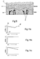
- the dimensions of the layer structure of human skin are in Fig. 10 illustrated more realistic.
- the epidermis with the stratum corneum as the uppermost skin layer comprises about 0.5 to 1 mm depth, while the blood capillaries 37 containing dermis reaches a depth range of a few millimeters.
- the blood contact is detected after a waiting time after the forward movement by the detection means 24 in the sense of a success check.
- the collection time can be optimized because in a liquid contact with blood from the puncture wound has certainly nachgeflossen. If, on the other hand, no blood contact has been detected after the waiting time, the measurement by the control device 32 can be aborted. This does not give false results due to missing or too small blood volume.
- the control device 32 outputs a corresponding message to the user.
- the collection process does not have to be static, but can be carried out in the course of a further return movement of the lancing element 10.
- collecting on the skin surface 34 is possible, as it is in Fig. 5 is shown.
- a liquid contact by the lancing member 16 as a measuring electrode which dips into a leaked blood droplet 50 and thus is in fluidic contact with the skin, and the pressure applied to the skin pressure ring 30 can be reliably detected as a counter electrode.
- the pressure ring is additionally designed to assist the blood flow under pressure and to open the wound, so that the contact between the lancing device and the skin and thus the pain for the user is minimal.
- lancing profile is to be understood here as the time course of the puncturing movement, as represented as a function of puncture depth over time.
- the lancing member shown in the bleeding, pain-sensitive skin area 52 is inserted in a forward movement 54 to a predetermined depth 56 quickly and immediately withdrawn in a retracting movement 58 to a depth of about 0.5 mm.
- the retraction phase is in the order of magnitude of the duration of the forward movement, ie a few 100 microseconds.
- the retraction position 60 may be in the region of the stratum corneum and thus outside of the pain region 52.
- This is followed by a collection phase 62, in which blood is taken up while the lancing element is slowly pulled back to the skin surface.
- This collection phase 62 lasts a few seconds, with the path d2 traveled by the lancing member being substantially smaller than the withdrawal path d1 during the withdrawal phase 58. The later slower withdrawal relaxes the skin, so that the puncture channel is not immediately blocked again.
- the collection process takes a certain amount of time, it is expediently carried out in the nerve-free outer skin zone.
- the collection below the skin surface i. in the inserted state, is also important to avoid blood leakage to the skin and thus to allow a particularly hygienic removal process.
- blood already leaked onto the skin surface can only be removed cleanly with the piercing element 10 if the capillary force of the capillary 18 at this point is sufficiently great. This is the case when the lancing member 16 is at least slightly pricked state, because the Kapillartiefe is smaller towards the top and thus the capillary force also decreases.
- a detection of the skin surface can be carried out, for example, by an impedance measurement before the actual piercing process.
- the position of the skin surface is detected during a slow forward movement of the lancing element 10:
- Switching between the different areas of the lancing profile can either be controlled by the position (depth) or timed.
- the transition between the areas with different speeds can be done by a discontinuous change or be fluent (constant speed change).
- the continuous solution has the advantage that less drive energy is required and the regulation of the movement is simplified.
- the lancing member is completely withdrawn from the skin after a first rapid forward movement 54 and then re-stabbed in a second forward movement 54 'with a lesser depth of puncture. At this point, a blood contact is then detected, and then the collection process 62 carried out with slow retraction of the lancing member to the skin surface.
- the whole Retraction has the advantage that a possible rebounding of the lancing member takes place outside the skin and thus no damping is necessary, which greatly reduces the demands on the actuators.
- This lancing profile lends itself to a simple control variant.
- the skin surface can be detected before the time t0 in order to be able to determine the puncture depth precisely.
- This process could be done inductively or by impedance measurement by slowly moving the lancing element against the skin as described above until its surface is touched.
- the first lancing (fast in and out quickly) can then be done as it were "blind", i. E. without feedback through a control loop.
- the lancing member After the first lancing, the lancing member is moved more slowly forward than before (phase 54 '). This movement can also be done without a control loop. If the skin surface is reached (possibly detected by renewed skin detection), then a control signal can be triggered, which triggers the remaining portion of the lancing profile (collection phase). The reversal point 66 may be determined against the trigger signal by a time delay. This time delay must be short enough not to penetrate into pain zone 52 again. The collection process until t2 can then also be done without position control by simple control. Subsequently, the piercing element is withdrawn into the device until time t3 and thus the piercing element is removed from the skin.
- Fig. 11 For example, the time course of the measurement signal 68 for various possibilities of blood contact in the configuration Fig. 2 to 4 illustrated in more detail.
- the conductivity increases slowly to a kink point 70 slower until blood contact the tip 16 in the dermis 36 leads to a rapid increase in signal.
- a signal level 72 is reached, which is characteristic of a direct liquid contact and thus can serve as a comparison signal.
- the skin contact between the tip 16 and the ring electrode 30 and thus the ring radius is the skin contact first, the conductivity or impedance.
- the effective electrode area increases abruptly, and the signal is only influenced by the thickness of the skin layer between the blood zone 36 and the overlying ring 30 which is substantially smaller than the ring radius. Especially for a capacitive measurement, it is therefore advantageous if the ring 30 is electrically insulated from the skin surface 44.
- a liquid contact characteristic (and possibly empirically determinable) signal level 72 At the end of the forward movement, in the corresponding Fig. 2 the bleeding zone 36 is reached, which reaches a liquid contact characteristic (and possibly empirically determinable) signal level 72.
- the signal decreases on retraction and reaches the maximum value 72 again on the second contact with the blood.
- a success check for the blood uptake can be carried out in such a way that a comparison is made as to whether the high signal level is present again.
- Fig. 11c if the blood is not or only poorly flowing, the signal level continues to be in the retracted position so that, due to the change in the measurement signal after a given waiting time, the presence of an error case is detected in which collection of the body fluid is predeterminably unsuccessful.
- a critical signal change can be determined by comparison with the signal level at the beginning of the waiting time or by evaluating the slope of the waveform. Accordingly, the measurement can be aborted and the user warned.
Landscapes
- Health & Medical Sciences (AREA)
- Life Sciences & Earth Sciences (AREA)
- Molecular Biology (AREA)
- Heart & Thoracic Surgery (AREA)
- Physics & Mathematics (AREA)
- Veterinary Medicine (AREA)
- Biophysics (AREA)
- Pathology (AREA)
- Engineering & Computer Science (AREA)
- Animal Behavior & Ethology (AREA)
- Surgery (AREA)
- Medical Informatics (AREA)
- Public Health (AREA)
- General Health & Medical Sciences (AREA)
- Biomedical Technology (AREA)
- Hematology (AREA)
- Dermatology (AREA)
- Pain & Pain Management (AREA)
- Nuclear Medicine, Radiotherapy & Molecular Imaging (AREA)
- Radiology & Medical Imaging (AREA)
- Measurement Of The Respiration, Hearing Ability, Form, And Blood Characteristics Of Living Organisms (AREA)
- Extraction Or Liquid Replacement (AREA)
- Electrical Discharge Machining, Electrochemical Machining, And Combined Machining (AREA)
- Sampling And Sample Adjustment (AREA)
- Measuring Pulse, Heart Rate, Blood Pressure Or Blood Flow (AREA)
Description
- Die Erfindung betrifft eine Vorrichtung zur Entnahme von Körperflüssigkeit, insbesondere Blut, gemäß dem Oberbegriff des Patentanspruchs 1.
- Solche Entnahmevomchtungen für kleine Körperflüssigkeitsmengen dienen vor allem Diabetikern zur täglich mehrfach durchgeführten Blutzucker-Selbstkontrolle. Neuere Konzepte sehen eine messende MIkronadel als Einwegartikel (Disposable) in einem Handgerät vor, um einen Hauteinstich zu erzeugen, daraus eine kleine Menge Blut unter Ausnutzung von Kapillarkräf ten zu entnehmen und diese Blutprobe zu analysieren. Mit einem solchen integrierten System sollen in einem weitgehend automatischen Messablauf auch von Laien die erforderlichen Schritte einfach und schnell vorgenommen werden können. Um dies zu erreichen, ist es wichtig, dass Stech- und Sammelvorgang geräteseitig auf das Disposable abgestimmt sind, damit effizient, schnell und schmerzfrei Blut oder gegebenenfalls Gewebeflüssigkeit gesammelt werden kann.
- In diesem Zusammenhang wurde bereits vorgeschlagen, zur Steuerung der vorwärts gerichteten Einstechbewegung einen Hautkontakt zu erfassen, um so eine definierte Einstechtiefe erreichen zu können. Eine solche Bewegungssteuerung muss aber mit großern apparativem Aufwand an die gewünschte hohe Einstechgeschwindigkeit angepasst werden. Vor allem ist aber nachteilig, dass damit keine Erkenntnis über einen tatsächlichen Erfolg der Blutaufnahme gewonnen werden kann.
- Zur Optimierung der Blutgewinnung beschreibt die
WO 03/009759 A1 - Aus der
WO2004/080306 ist ein Stechsystem bekannt, welches dazu ausgebildet ist, eine charakteristische Größe (z.B. Impedanz) im Zuge der Stechbewegung und gegebenenfalls auch noch beim Zurückziehen zu erfassen. Dies soll allerdings nur einer Hauterkennung als solcher dienen, um gegebenenfalls die Eindringtiefe oder Einddngstabilität bzw. die Verweildauer dem Benutzer anzuzeigen. Eine Erfolgskontrolle für einen tatsächlichen Flüssigkeitskontakt über die Hautdetektion hinaus ist hingegen an keiner Stelle angesprochen. - Ausgehend hiervon liegt der Erfindung die Aufgabe zugrunde, die im Stand der Technik aufgetretenen Nachteile zu vermeiden und bei einfacher Benutzung eine insbesondere hinsichtlich Zuverlässigkeit, Effizienz, Schmerzminimierung und Hygiene optimierte Gewinnung der Körperflüssigkeit zu ermöglichen.
- Zur Lösung dieser Aufgabe wird die in den unabhängigen Patentansprüchen jeweils angegebene Merkmalskombination vorgeschlagen.
- Ein besonderer Efindungsaspekt Iiegt darin, den Sammelvorgang nicht sta-tisch durchzuführen, sondern in einer schmerzarmen Zone einen verbesserten Blutzufluss zu gewährleisten. Dementsprechend wird vorgeschlagen, dass das Stechelement nach der Vorwärtsbewegung in einer Rückziehphase um einen ersten Weg und in einer späteren Sammelphase um einen zweiten Weg zurückgezogen wird, wobei die Rückziehphase kürzer als die Sammelphase und der erste Weg größer als der zweite Weg und der zweite Weg größer als Null ist. Eine entsprechende Vorrichtung sieht vor, dass der Stechantrieb zur Rückbewegung des Stechelements in einer Rückziehphase um einen ersten Weg und in einer späteren Sammelphase um einen zweiten Weg ausgebildet ist, wobei die Rückziehphase kürzer als die Sammelphase und der erste Weg größer als der zweite Weg und der zweite Weg größer als Null ist. Damit kann rasch und schmerzarrn ein Stichkanal in einer Blutzone geschaffen werden, während der Sammelvorgang mit der erforderlichen Dauer für den Selbsttransport der Flüssigkeit in der Kapillarstruktur in einer unempfindlicheren äußeren Hautzone erfolgt. Überraschend hat sich gezeigt, dass durch das langsame Zurückziehen die Sammeleffizienz erheblich besser ist als bei statischen Sammelpositlonen. Eine mögliche Erklärung kann darin liegen, dass die Haut nach der schnellen Stechbewegung durch das Stechorgan eingedrückt ist und diese Andruckkraft zunächst das Fließen des Blutes verhindert. Beim langsamen Zurückziehen während der Sammelphase wird jedoch die Haut wieder entspannt, so dass Blut besser Nachfließen kann. Denkbar ist es auch, dass durch das Zurückziehen des Stechelements eine Art Saugeffekt erreicht wird, so dass zusätzliches Blut zur Verfügung steht. Dabei ist das Sammeln im eingestochenen Zustand hygienisch günstig und für die dosierte Entnahme kleiner Flüssigkeitsmengen effizient.
- Vorteilhafte Ausgestaltungen und Weiterbildungen der Erfindung ergeben sich aus den abhängigen Ansprüchen.
- Durch die rasche Rückbewegung in eine Rückziehposition von geringerer Stechtiefe wird der Schmerzbereich des Körperteils bzw. der Haut schnell verlassen. In dieser äußeren nicht-blutgebenden Zone wird dann nach einer Wartezeit kontrolliert, ob Blut über den Stichkanal nachfliesst. Bei Flüssigkeitskontakt kann von einer hohen Sammelerfolgsrate ausgegangen werden, ohne überflüssiges Totvolumen. Außerdem kann noch in der Haut besonders hygienisch Flüssigkeit aufgenommen werden, ohne dass austretendes Blut zu sehen wäre. Zur Erfassung des Flüssigkeitskontakts eignet sich vor allem eine Impedanzmessung unter Einbeziehung des Stechorgans als Elektrode. Nach Maßgabe eines erfassten Körperflüssigkeitskontakts lässt sich der Erhalt von KörperFlüssigkeit aus dem Körperteil bzw. aus der Stichwunde kontrollieren. Die Wahrscheinlichkeit für eine erfolgreiche Aufnahme der Flüssigkeit wird durch eine solche Kontrolle erheblich erhöht. Hierdurch kann auch die optimale Sammelzeit abgewartet werden. Gegebenenfalls wird bei ausbleibendem Kontakt ein Fehlersignal generiert und der Entnahmevorgang abgebrochen.
- Besonders bevorzugt wird die Körperflüssigkeit nach dem schnellen Zurückziehen des Stechelements während einer Sammelphase in der äußeren schmerzarmen Hautschicht aufgenommen. Dabei wird das Stechelement zumindest während eines Teils der Sammelphase gleichförmig oder mit veränderlicher Geschwindigkeit zurückgezogen, wodurch die Sammeleffizienz entscheidend verbessert wird. Die Sammelzeit sollte ausreichend bemessen sein, um unter der kapillaraktiven Wirkung eine hinreichende Flüssigkeitsaufnahme sicherzustellen.
- Insbesondere sind alle offenbarten Ausführungsformen hinsichtlich der Körperflüssigkeitserfassung und den Stechprofilen miteinander kombinierbar.
- Im Folgenden wird die Erfindung anhand der in der Zeichnung schematisch dargestellten Ausführungsbeispiele näher erläutert. Es zeigen
- Fig. 1
- ein Blockschaltbild einer Vorrichtung zur Entnahme und ggf. Analyse von Blut aus einem Körperteil;
- Fig. 2 bis 5
- ein Stechelement der Vorrichtung nach
Fig. 1 in verschiedenen Stechpositionen in vereinfachter Schrittdarstellung; - Fig. 6 bis 9
- verschiedene Stechprofile beim Einsatz des Stechelements;
- Fig. 10
- die Anatomie der menschlichen Haut in einer schaubildlichen Darstellung;
- Fig.11
- den Signalverlauf in verschiedenen Konstellationen eines Körperflüssigkeitskontakts.
- Die in der Zeichnung dargestellte Vorrichtung dient der Selbstentnahme einer Blutprobe durch einen Benutzer für Analysezwecke, insbesondere zur Blutzuckerkontrolle. Die Vorrichtung umfasst ein Stechelement 10 als Einmalartikel zur Blutaufnahme und ein Handgerät 12 zur automatischen Handhabung des eingesetzten Stechelements 10.
- Das in
Fig. 1 gezeigte Stechelement 10 ist als so genannter "Microsampler" zur Gewinnung einer kleinen Blutmenge aus einem Körperteil 14, insbesondere einer Fingerkuppe vorgesehen. Es besteht als Flachformteil aus dünnem Edelstahlblech und weist eine distal angeformte Spitze 16 als Stechorgan auf, die über einen halboffenen rillenförmigen Kapillarkanal 18 mit einer Sammelstelle 20 verbunden ist, welche als Reaktionsbereich für einen Nachweis eines Analyten, z. B. Glucose ausgebildet sein kann. Der Blutglucosenachweis speziell mittels berührungsloser optischer Methoden ist im Stand der Technik an sich bekannt und wird daher hier nicht näher erläutert. Optional kann das gesammelte Blut aber auch in eine Analyseeinheit transferiert werden, um dort den Analyten zu bestimmen. - Das Gerät bzw. Instrument 12 weist einen Stechantrieb 22 für eine kontrollierte Vorwärts- und Rückbewegung des Stechelements 10 und Detektionsmittel 24 zur Erfassung eines Blutkontakts des Stechelements 10 während einer Sammelphase auf. Der Stechantrieb 22 umfasst eine mechanisch und/oder elektrisch arbeitende Antriebseinheit .26, die mit dem Stechelement 10 gekoppelt ist. Speziell kann ein zweistufiger Hybridantrieb vorgesehen sein, bei dem eine schnelle Bewegung von einer Mechanik, beispielsweise einer Antriebsfeder oder Antriebskulisse übernommen wird, während ein langsamere geregelte Bewegung über einen Elektromotor erfolgt. Alternativ kann auch ein elektromagnetischer Antrieb nach Art einer Lautsprecherspule den Stechhub bewirken. Der Stechantrieb 22 umfasst ferner eine Steuereinheit 28 für die Ablaufsteuerung oder -regelung der Blutentnahme und insbesondere der Stechbewegung. Zweckmäßig wird hierfür ein Mikrocontroller eingesetzt, der gegebenenfalls zusätzlich benutzerspezifisch parametrisiert werden kann.
- Die Detektionsmittel 24 können den Blutkontakt während der Sammelphase durch eine Impedanzmessung über das Stechorgan 16 und einen von dem Stechorgan axial durchsetzten und in Anlage mit dem Körperteil 14 befindlichen Andruckring 30 als Gegenelektrode erfassen. Das aus elektrisch leitfähigem Material bestehende Stechorgan kann hierbei mit einem elektrischen Wechselspannungssignal, z.B. 4 Vpp und 10 kHz gefahrlos angesteuert werden, wobei durch einen fluidischen Kontakt die Impedanz in dem Pfad zwischen Stechorgan und Gegenelektrode signifikant abnimmt. Eine Kontrolleinrichtung 32 ermöglicht eine Erfolgskontrolle der Blutaufnahme in Abhängigkeit von dem erfassten Flüssigkeitskontakt, wie es nachstehend näher erläutert wird.
- Die
Fig. 2 bis 5 veranschaulichen den Ablauf der Blutgewinnung mittels des Stechelements 10. Zunächst wird in einer distal gerichteten Vorwärtsbewegung das Stechorgan 16 durch die Hautoberfläche 34 hindurch in das Körperteil 14 auf eine vorgegebene Tiefe eingestochen, so dass eine blutgebende Zone 36 in der Dermis erreicht wird. In diesem Bereich enden die Blutkapillaren, die durch das Stechorgan geöffnet werden können. Zugleich ist aber in diesem tieferen Bereich 36 aufgrund der dort vorhandenen Nervenzellen auch das Schmerzempfinden hoch. Aus diesem Grund ist es günstig, wenn das Stechelement unmittelbar nach der Vorwärtsbewegung in einer Rückziehbewegung aus der tiefsten Einstechposition 38 in eine Rückziehposition 40 von geringerer Stechtiefe zurückgezogen wird (Fig. 3 ). Bevorzugt liegt diese Rückziehposition im Bereich der Epidermis 42, speziell im Stratum Corneum 44. Nach dem schnellen Zurückziehen des Stechelements 10 verstreicht eine gewisse Zeit, bis das Blut 46 über den erzeugten Stichkanal 48 in die Epidermis nachfliest. - Die Dimensionen des Schichtaufbaus der menschlichen Haut sind in
Fig. 10 realistischer veranschaulicht. Die Epidermis mit dem Stratum Corneum als oberster Hautschicht umfasst etwa 0,5 bis 1 mm Tiefe, während die Blutkapillaren 37 enthaltende Dermis in einen Tiefenbereich von einigen Millimetern erreicht. - Gemäß
Fig. 4 wird in der zurückgezogenen Sammelposition 40 der Blutkontakt nach einer Wartezeit nach der Vorwärtsbewegung durch die Detektionsmittel 24 im Sinne einer Erfolgskontrolle erfasst. Auf diese Weise kann die Sammelzeit optimiert werden, da bei einem Flüssigkeitskontakt mit Sicherheit Blut aus der Stichwunde nachgeflossen ist. Wenn hingegen nach der Wartezeit kein Blutkontakt detektiert wurde, kann die Messung durch die Kontrolleinrichtung 32 abgebrochen werden. Dadurch entstehen keine falschen Resultate durch fehlendes oder zu kleines Blutvolumen. Zweckmäßig gibt die Kontrolleinrichtung 32 eine entsprechende Meldung an den Benutzer aus. - Der Sammelvorgang braucht nicht statisch zu erfolgen, sondern kann im Zuge einer weiteren Rückbewegung des Stechelements 10 durchgeführt werden. Optional ist auch ein Sammeln auf der Hautoberfläche 34 möglich, wie es in
Fig. 5 gezeigt ist. Hierbei kann ein Flüssigkeitskontakt durch das Stechorgan 16 als Messelektrode, welche in einen ausgetretenen Blutstropfen 50 eintaucht und damit in fluidischem Kontakt mit der Haut steht, und dem an die Haut anliegenden Andruckring 30 als Gegenelektrode zuverlässig erfasst werden. Der Andruckring ist zusätzlich dafür vorgesehen, den Blutfluss unter Druck zu unterstützen und die Wunde zu öffnen, so dass der Kontakt zwischen Stechorgan und Haut und damit der Schmerz für den Benutzer minimal ist. - Für eine möglichst erfolgreiche und schmerzarme Blutaufnahme sind die in den
Fig. 6 bis 9 gezeigten Stechprofile besonders vorteilhaft. Unter dem Begriff "Stechprofil" ist hierbei der Zeitverlauf der Stechbewegung zu verstehen, wie er als Funktion der Stechtiefe über der Zeit dargestellt ist. - Bei dem in
Fig. 6 gezeigten Stechprofil wird das Stechorgan in den blutgebenden, schmerzempfindlichen Hautbereich 52 in einer Vorwärtsbewegung 54 bis zu einer vorgegebenen Tiefe 56 schnell eingestochen und sogleich in einer Rückziehbewegung 58 bis auf eine Tiefe von ca. 0,5 mm zurückgezogen. Die Rückziehphase liegt dabei in der Größenordnung der Dauer der Vorwärtsbewegung, d. h. wenigen 100 µs. Die Rückziehposition 60 kann sich im Bereich des Stratum Corneums und damit außerhalb des Schmerzbereichs 52 befinden. Anschließend folgt eine Sammelphase 62, in welcher Blut aufgenommen wird, während das Stechelement langsam bis auf die Hautoberfläche zurückgezogen wird. Diese Sammelphase 62 dauert einige Sekunden, wobei der durch das Stechorgan zurückgelegte Weg d2 wesentlich kleiner ist als der Rückziehweg d1 während der Rückziehphase 58. Durch das spätere langsamere Zurückziehen relaxiert die Haut, so dass der Stichkanal nicht sogleich wieder blockiert wird. - Da der Sammelvorgang eine gewisse Zeit benötigt, wird er zweckmäßigerweise in der nervenfreien äußeren Hautzone vollzogen. Das Sammeln unterhalb der Hautoberfläche, d.h. im eingestochenen Zustand, ist ebenfalls wichtig, um einen Blutaustritt auf die Haut zu vermeiden und somit einen besonders hygienischen Entnahmevorgang zu ermöglichen. Hinzu kommt, dass bereits auf die Hautoberfläche ausgetretenes Blut nur dann sauber mit dem Stechelement 10 entfernt werden kann, wenn die Kapillarkraft der Kapillare 18 an dieser Stelle genügend groß ist. Dies ist dann der Fall, wenn das Stechorgan 16 sich zumindest in leicht eingestochenem Zustand befindet, weil zu der Spitze hin die Kapillartiefe kleiner wird und damit die Kapillarkraft auch abnimmt.
- Für das Stechprofil nach
Fig. 6 sind elektrische oder elektromagnetische Antriebe besser geeignet als rein mechanische Antriebe, weil bei letzteren Prelleffekte schwerer zu kontrollieren sind (eine Dämpfung lässt sich einfacher elektrischer realisieren als durch eine mechanische Lösung). - Um die Stechtiefe definiert einstellen zu können, kann eine Detektion der Hautoberfläche beispielsweise durch eine Impedanzmessung vor dem eigentlichen Stechvorgang vorgenommen werden. Die Position der Hautoberfläche wird dabei während einer langsamen Vorwärtsbewegung des Stechelements 10 detektiert:
- Das Umschalten zwischen den verschiedenen Bereichen des Stechprofils kann entweder durch die Position (Tiefe) gesteuert werden oder zeitgesteuert sein. Der Übergang zwischen den Bereichen mit unterschiedlichen Geschwindigkeiten kann durch eine unstetige Änderung erfolgen oder aber fließend sein (stetige Geschwindigkeitsänderung). Die stetige Lösung hat den Vorteil, dass weniger Antriebsenergie erforderlich ist und die Regelung der Bewegung vereinfacht wird.
- Das in
Fig. 7 gezeigte Stechprofil unterscheidet sich nur durch eine zusätzliche Stufe 64 während der Sammelphase 62. Hier erfolgt nach dem schnellen Zurückziehen bis Tiefe B ein etwas langsameres Zurückziehen bis Tiefe C, wobei sich während dieses Intervalls die Haut entspannt. Der eigentliche Sammelvorgang erfolgt dann nochmals verlangsamt von der Tiefe C bis an die Hautoberfläche. Dadurch kann eine Verkürzung des gesamten Stech-und Sammelvorgangs erreicht werden. - Eine ähnliche Ausführung sieht gemäß
Fig. 8 vor, dass nach der schnellen Rückziehphase 58 die Hautentspannung durch langsames Zurückziehen des Stechorgans bis zum Zeitpunkt t1 erreicht wird, und anschließend bis zum Zeitpunkt t2 bei ruhendem Stechorgan weiter gesammelt wird. Hierbei ist allerdings eine seitliche Verschiebung des Stechorgans gegenüber der Haut für den Benutzer deutlicher zu spüren. - Bei dem Stechprofil nach
Fig. 9 wird das Stechorgan nach einer ersten schnellen Vorwärtsbewegung 54 vollständig aus der Haut zurückgezogen und anschließend in einer zweiten Vorwärtsbewegung 54' mit geringerer Stechtiefe erneut eingestochen. In diesem Punkt wird dann ein Blutkontakt detektiert, und anschließend der Sammelvorgang 62 unter langsamem Zurückziehen des Stechorgans bis zur Hautoberfläche durchgeführt. Das vollständige Zurückziehen besitzt den Vorteil, dass ein eventuelles Nachprellen des Stechorgans außerhalb der Haut stattfindet und somit keine Dämpfung nötig ist, was die Anforderungen an die Aktuatorik stark reduziert. - Dieses Stechprofil bietet sich für eine einfache Regelungsvariante an. Zunächst kann vor der Zeit t0 die Hautoberfläche detektiert werden, um die Stechtiefe genau bestimmen zu können. Dieser Vorgang könnte induktiv oder durch eine Impedanzmessung erfolgen, indem wie oben beschrieben das Stechelement langsam gegen die Haut bewegt wird, bis deren Oberfläche angetastet wird. Der erste Stechvorgang (schnell hinein und schnell heraus) kann dann gleichsam "blind" erfolgen, d.h. ohne Rückkopplung durch einen Regelkreis. Dies hat den Vorteil, dass insbesondere im Falle der Verwendung eines elektromagnetischen Spulenantriebs eine schnelle und kostspielige Regelungselektronik vermieden werden kann. Bei einem Hybridantrieb würde dieser schnelle Stechvorgang vom mechanischen Teil übernommen (z. B. Feder- oder Kulissen-Antrieb). Nach dem ersten Stechvorgang wird das Stechorgan langsamer vorwärts bewegt als zuvor (Phase 54'). Diese Bewegung kann ebenfalls ohne Regelschleife erfolgen. Ist die Hautoberfläche erreicht (ggf. erfasst durch erneute Hautdetektion), so kann ein Steuersignal ausgelöst werden, welches den verbleibenden Abschnitt des Stechprofils (Sammelphase) triggert. Der Umkehrpunkt 66 kann gegenüber dem Triggersignal durch eine zeitliche Verzögerung bestimmt werden. Diese zeitliche Verzögerung muss kurz genug sein, um nicht wieder bis in die Schmerzzone 52 vorzudringen. Der Sammelvorgang bis t2 kann dann ebenfalls ohne Positionsregelung durch einfache Steuerung erfolgen. Anschließend wird das Stechelement bis zum Zeitpunkt t3 in das Gerät zurückgezogen und das Stechorgan somit von der Haut entfernt.
- In
Fig. 11 ist der zeitliche Verlauf des Messsignals 68 für verschiedene Möglichkeiten eines Blutkontakts in der Konfiguration nachFig. 2 bis 4 näher veranschaulicht. Beim Einstich in trockene Haut nimmt die Leitfähigkeit bis zu einer Knickstelle 70 zunächst langsamer zu, bis ein Blutkontakt der Spitze 16 in der Dermis 36 zu einem raschen Signalanstieg führt. Am Ende der Vorwärtsbewegung wird ein Signalpegel 72 erreicht, der für einen direkten Flüssigkeitskontakt charakteristisch ist und somit als Vergleichssignal dienen kann. Hierbei ist zu berücksichtigen, dass beim Hautkontakt zunächst die Leitfähigkeit bzw. Impedanz der Hautfläche zwischen der Spitze 16 und der Ringelektrode 30 und somit der Ringradius maßgeblich ist. Beim Eintauchen der Spitze 16 in die Körperflüssigkeit 16 vergrößert sich die wirksame Elektrodenfläche schlagartig, und das Signal wird nur durch die im Vergleich zum Ringradius wesentlich geringere Dicke der Hautschicht zwischen der Blutzone 36 und dem darüber liegenden Ring 30 beeinflusst. Besonders für eine kapazitive Messung ist es daher vorteilhaft, wenn der Ring 30 gegenüber der Hautoberfläche 44 elektrisch isoliert ist. - Gemäß
Fig. 11a wird somit am Ende der Vorwärtsbewegung, in der entsprechendFig. 2 die blutgebende Zone 36 erreicht wird, der für einen Flüssigkeitskontakt charakteristische (und gegebenenfalls empirisch bestimmbare) Signalpegel 72 erreicht. Beim anschließenden Zurückziehen in die Sammelposition 40 gemäßFig. 3 kann dann der Fall eintreten, dass eine kurze Zeit verstreicht, bis die Körperflüssigkeit bis zur zurückgezogenen Nadelspitze nachgeflossen ist. Dementsprechend nimmt das Signal beim Zurückziehen ab und erreicht beim zweiten Kontakt mit dem Blut wieder den Höchstwert 72. Somit kann nach einer vorgegebenen Wartezeit eine Erfolgskontrolle für die Blutaufnahme dahingehend durchgeführt werden, dass ein Vergleich durchgeführt wird, ob der hohe Signalpegel wieder vorliegt. - Für den Fall eines schnellen Nachfließens der Körperflüssigkeit reißt der Flüssigkeitskontakt zu der zurückbewegten Spitze 16 nicht ab, und der Signalpegel bleibt konstant hoch, wie es in
Fig. 11b gezeigt ist. Auch hier ist eine positive Erfolgskontrolle möglich. - Hingegen nimmt entsprechend
Fig. 11c bei nicht oder nur schlecht nachfließendem Blut der Signalpegel auch in der zurückgezogenen Position weiter ab, so dass aufgrund der Änderung des Messsignals nach einer gegebenen Wartezeit das Vorliegen eines Fehlerfalls erkannt wird, in welchem ein Sammeln der Körperflüssigkeit vorrausichtlich nicht erfolgreich ist. Eine kritische Signaländerung kann durch einen Vergleich mit dem Signalpegel am Anfang der Wartezeit oder durch eine Auswertung der Steigung des Signalverlaufs bestimmt werden. Demgemäß kann die Messung abgebrochen und der Benutzer gewarnt werden.
Claims (21)
- Vorrichtung zur Entnahme von Körperflüssigkeit, insbesondere Blut, mit einem eine Kapillarstruktur (18) zur Aufnahme der Körperflüssigkeit aufweisenden Stechelement (10) zum Einstechen durch die Haut in ein Körperteil (14) und einem Stechantrieb (22) für eine Vorwärts- und Rückbewegung des Stechelements (10), dadurch gekennzeichnet, dass der Stechantrieb (22) zur Rückbewegung des Stechelements (10) in einer Rückziehphase (58) um einen ersten Weg (d1) und in einer späteren Sammelphase (62) um einen zweiten Weg (d2) ausgebildet ist, wobei die Rückziehphase (58) kürzer als die Sammelphase (62) und der erste Weg (d1) größer als der zweite Weg (d2) und der zweite Weg großer als Null ist.
- Vorrichtung nach Anspruch 1, dadurch gekennzeichnet, dass die Rückziehphase (58) in der Größenordnung der Dauer der Vorwärtsbewegung (54) liegt.
- Vorrichtung nach Anspruch 1 oder 2, dadurch gekennzeichnet, dass die Sammelphase (62) gegenüber der Rückziehphase (58) um das 10-bis 10.000-fache verlängert ist.
- Vorrichtung nach einem der Ansprüche 1 bis 3, dadurch gekennzeichnet, dass der Stechantrieb (22) das Stechelement (10) während der Sammelphase (62) vorzugsweise mit gleichförmiger Geschwindigkeit zurückzleht.
- Vorrichtung nach einem der Ansprüche 1 bis 4, dadurch gekennzeichnet, dass der Stechantrieb (22) das Stechelement (10) in einem ersten Zeitabschnitt der Sammelphase (62) gegenüber einem nachfolgenden zweiten Zeitabschnitt schneller zurückzieht.
- Vorrichtung nach einem der Ansprüche 1 bis 5, dadurch gekennzeichnet, dass der Stechantrieb (22) das Stechelement (10) in dem zweiten Zeitabschnitt für eine bestimmte Verweilzeit anhält.
- Vorrichtung nach einem der Ansprüche 1 bis 6, dadurch gekennzeichnet, dass der Stechantrieb (22) das Stechelement (10) während der Rückziehphase (58) vollständig aus der Haut zurückzieht und vor der Sammelphase (62) mit geringerer Stechtiefe erneut einsticht.
- Vorrichtung nach einem der Ansprüche 1 bis 7, dadurch gekennzeichnet, dass der Stechantrieb (22) das Stechelement (10) während der Sammelphase (62) um einen zweiten Weg zwischen 2 mm und 0,1 mm zurückbewegt.
- Vorrichtung nach einem der Ansprüche 1 bis 8, dadurch gekennzeichnet, dass die Bewegung des Stechelements (10) durch eine Zeit-oder Positionserfassung gesteuert ist.
- Vorrichtung nach einem der Ansprüche 1 bis 9, gekennzeichnet durch ein Detektionsmittel (24), welches einen Körperflüssigkeftskontakt des Stechelements (10) zumindest am Beginn und Ende einer Wartezeit nach der Vorwärtsbewegung (54) während einer Sammelphase (62) für eine Erfolgskontrolle durch ein Messsignal erfasst.
- Vorrichtung nach Anspruch 10. dadurch gekennzeichnet, dass das Stechelement (10) mittels des Stechantriebs (22) nach der Vorwärtsbewegung (54) in einer Rückziehbewegung aus der tiefsten Einstechposition in eine Rückziehposition von geringerer Stechtiefe zurückziehbar ist, und dass das Detektionsmittel (24) in der Rückziehposition bei einem Körpertlüssigkeitskontakt anspricht.
- Vorrichtung nach Anspruch 10 oder 11, dadurch gekennzeichnet, dass der Körpertlüssigkeitskontaki nach der Vorwärtsbewegung (54) vorzugsweise innerhalb des Körperteils (14) erfasst wird, wobei eine gegebene Signalveränderung als Fehlerfall erkannt wird.
- Vorrichtung nach einem der Ansprüche 10 bis 12, dadurch gekennzeichnet, dass der Stechantrieb (22) dazu ausgebildet ist, das Stechelement (10) nach einer ersten Vorwärtsbewegung (54) aus der Haut zurückzuziehen und sogleich in einer zweiten Vorwärtsbewegung (54) mit geringerer Stechtiefe erneut einzustechen, und dass anschließend das Detektionsmittel (24) bei einem Körperflüssigkeitskontakt anspricht.
- Vorrichtung nach einem der Ansprüche 1 bis 13, dadurch gekennzeichnet, dass der Stechantrieb (22) zweistufig ausgebildet ist, wobei eine vorzugsweise mechanisch arbeitende erste Antriebsstufe für eine schnelle Bewegung und eine vorzugsweise elektrisch arbeitende zweite Antriebsstufe für eine langsamere geregelte Bewegung des Stechelements (10) vorgesehen ist.
- Vorrichtung nach einem der Ansprüche 10 bis 14, dadurch gekennzeichnet, dass der Körperflüssigkeitskontakt über das Stechelement (10) und ein in Anlage mit dem Körperteil (14) stehendes, vorzugsweise elektrisch isoliertes Kontaktelement (30) detektierbar ist.
- Vorrichtung nach einem der Ansprüche 10 bis 15, gekennzeichnet durch Elektroden (10,30) als Detektionsmittel zur Erfassung eines Körperflüssigkeitskontakts des Stechelements (10) auf der Haut außerhalb des Körperteils (14), wobei die Elektroden durch das über die Körperflüssigkeit in fluidischen Kontakt mit der Haut befindliche Stechelement (10) und ein in Anlage mit der Haut stehendes Kontaktelement (30) gebildet sind.
- Vorrichtung nach einem der Ansprüche 10. bis 16, dadurch gekennzeichnet, dass die Detektionsmittel (10,30;24) den Körperflüssigkehskontakt bei Erreichen eines gegebenenfalls empirisch ermittelten Signalpegels eines elektrischen Messparameters insbesondere kapazitiv oder induktiv oder resistiv erfassen.
- Vorrichtung nach einem der Ansprüche 10 bis 17, dadurch gekennzeichnet, dass der Körperflüssigkeitskontakt über das Stechelement (10) durch eine Impedanzmessung gegenüber der Haut erfassbar ist.
- Vorrichtung nach einem der Ansprüche 10 bis 18, dadurch gekennzeichnet, dass der Körperflüssigkeitskontakt über optische Detektionsmittel vorzugsweise durch die Kapillarstruktur (18) oder einen Leichtleiter hindurch innerhalb des Körperteils (14) erfassbar ist.
- Vorrichtung nach einem der Ansprüche 10 bis 19, gekennzeichnet durch eine Kontrolleinrichtung (32) zur Erfolgskontrolle der Flüssigkeitsaufnahme nach Maßgabe des detektierten Körperflüssigkeftskontakts.
- Vorrichtung nach Anspruch 20, dadurch gekennzeichnet, dass die Kontrolleinrichtung (32) bei ausbleibendem Körperflüssigkeitskontakt ein Fehlersignal generiert und den Entnahmevorgang abbricht.
Priority Applications (4)
| Application Number | Priority Date | Filing Date | Title |
|---|---|---|---|
| PL09173523T PL2140811T3 (pl) | 2005-04-07 | 2006-04-06 | Urządzenie i sposób pobierania płynu ustrojowego |
| PL06724086T PL1868500T3 (pl) | 2005-04-07 | 2006-04-06 | Sposób i urządzenie do pobierania płynu ustrojowego |
| EP06724086A EP1868500B1 (de) | 2005-04-07 | 2006-04-06 | Verfahren und vorrichtung zur entnahme von körperflüssigkeit |
| EP09173523A EP2140811B1 (de) | 2005-04-07 | 2006-04-06 | Vorrichtung und Verfahren zur Entnahme von Körperflüssigkeit |
Applications Claiming Priority (3)
| Application Number | Priority Date | Filing Date | Title |
|---|---|---|---|
| EP05007580A EP1709906A1 (de) | 2005-04-07 | 2005-04-07 | Verfahren und Vorrichtung zur Entnahme von Körperflüssigkeit |
| PCT/EP2006/003141 WO2006105968A1 (de) | 2005-04-07 | 2006-04-06 | Verfahren und vorrichtung zur entnahme von körperflüssigkeit |
| EP06724086A EP1868500B1 (de) | 2005-04-07 | 2006-04-06 | Verfahren und vorrichtung zur entnahme von körperflüssigkeit |
Related Child Applications (1)
| Application Number | Title | Priority Date | Filing Date |
|---|---|---|---|
| EP09173523A Division EP2140811B1 (de) | 2005-04-07 | 2006-04-06 | Vorrichtung und Verfahren zur Entnahme von Körperflüssigkeit |
Publications (2)
| Publication Number | Publication Date |
|---|---|
| EP1868500A1 EP1868500A1 (de) | 2007-12-26 |
| EP1868500B1 true EP1868500B1 (de) | 2009-10-21 |
Family
ID=34934830
Family Applications (3)
| Application Number | Title | Priority Date | Filing Date |
|---|---|---|---|
| EP05007580A Withdrawn EP1709906A1 (de) | 2005-04-07 | 2005-04-07 | Verfahren und Vorrichtung zur Entnahme von Körperflüssigkeit |
| EP09173523A Expired - Lifetime EP2140811B1 (de) | 2005-04-07 | 2006-04-06 | Vorrichtung und Verfahren zur Entnahme von Körperflüssigkeit |
| EP06724086A Expired - Lifetime EP1868500B1 (de) | 2005-04-07 | 2006-04-06 | Verfahren und vorrichtung zur entnahme von körperflüssigkeit |
Family Applications Before (2)
| Application Number | Title | Priority Date | Filing Date |
|---|---|---|---|
| EP05007580A Withdrawn EP1709906A1 (de) | 2005-04-07 | 2005-04-07 | Verfahren und Vorrichtung zur Entnahme von Körperflüssigkeit |
| EP09173523A Expired - Lifetime EP2140811B1 (de) | 2005-04-07 | 2006-04-06 | Vorrichtung und Verfahren zur Entnahme von Körperflüssigkeit |
Country Status (10)
| Country | Link |
|---|---|
| US (2) | US7833172B2 (de) |
| EP (3) | EP1709906A1 (de) |
| JP (1) | JP4796621B2 (de) |
| CN (2) | CN101155550B (de) |
| AT (1) | ATE446049T1 (de) |
| CA (1) | CA2602719C (de) |
| DE (1) | DE502006005187D1 (de) |
| ES (2) | ES2332146T3 (de) |
| PL (2) | PL2140811T3 (de) |
| WO (1) | WO2006105968A1 (de) |
Families Citing this family (53)
| Publication number | Priority date | Publication date | Assignee | Title |
|---|---|---|---|---|
| US8641644B2 (en) | 2000-11-21 | 2014-02-04 | Sanofi-Aventis Deutschland Gmbh | Blood testing apparatus having a rotatable cartridge with multiple lancing elements and testing means |
| US9427532B2 (en) | 2001-06-12 | 2016-08-30 | Sanofi-Aventis Deutschland Gmbh | Tissue penetration device |
| US9226699B2 (en) | 2002-04-19 | 2016-01-05 | Sanofi-Aventis Deutschland Gmbh | Body fluid sampling module with a continuous compression tissue interface surface |
| US9795747B2 (en) | 2010-06-02 | 2017-10-24 | Sanofi-Aventis Deutschland Gmbh | Methods and apparatus for lancet actuation |
| US7025774B2 (en) | 2001-06-12 | 2006-04-11 | Pelikan Technologies, Inc. | Tissue penetration device |
| AU2002315180A1 (en) | 2001-06-12 | 2002-12-23 | Pelikan Technologies, Inc. | Electric lancet actuator |
| US9248267B2 (en) | 2002-04-19 | 2016-02-02 | Sanofi-Aventis Deustchland Gmbh | Tissue penetration device |
| US7547287B2 (en) | 2002-04-19 | 2009-06-16 | Pelikan Technologies, Inc. | Method and apparatus for penetrating tissue |
| US8579831B2 (en) | 2002-04-19 | 2013-11-12 | Sanofi-Aventis Deutschland Gmbh | Method and apparatus for penetrating tissue |
| US8784335B2 (en) | 2002-04-19 | 2014-07-22 | Sanofi-Aventis Deutschland Gmbh | Body fluid sampling device with a capacitive sensor |
| US9314194B2 (en) | 2002-04-19 | 2016-04-19 | Sanofi-Aventis Deutschland Gmbh | Tissue penetration device |
| US8702624B2 (en) | 2006-09-29 | 2014-04-22 | Sanofi-Aventis Deutschland Gmbh | Analyte measurement device with a single shot actuator |
| US7175642B2 (en) | 2002-04-19 | 2007-02-13 | Pelikan Technologies, Inc. | Methods and apparatus for lancet actuation |
| US9795334B2 (en) | 2002-04-19 | 2017-10-24 | Sanofi-Aventis Deutschland Gmbh | Method and apparatus for penetrating tissue |
| US7198606B2 (en) | 2002-04-19 | 2007-04-03 | Pelikan Technologies, Inc. | Method and apparatus for a multi-use body fluid sampling device with analyte sensing |
| US8574895B2 (en) | 2002-12-30 | 2013-11-05 | Sanofi-Aventis Deutschland Gmbh | Method and apparatus using optical techniques to measure analyte levels |
| WO2004107964A2 (en) | 2003-06-06 | 2004-12-16 | Pelikan Technologies, Inc. | Blood harvesting device with electronic control |
| WO2006001797A1 (en) | 2004-06-14 | 2006-01-05 | Pelikan Technologies, Inc. | Low pain penetrating |
| US8282576B2 (en) | 2003-09-29 | 2012-10-09 | Sanofi-Aventis Deutschland Gmbh | Method and apparatus for an improved sample capture device |
| EP1680014A4 (de) | 2003-10-14 | 2009-01-21 | Pelikan Technologies Inc | Verfahren und gerät für eine variable anwenderschnittstelle |
| EP1706026B1 (de) | 2003-12-31 | 2017-03-01 | Sanofi-Aventis Deutschland GmbH | Verfahren und vorrichtung zur verbesserung der fluidströmung und der probennahme |
| US7822454B1 (en) | 2005-01-03 | 2010-10-26 | Pelikan Technologies, Inc. | Fluid sampling device with improved analyte detecting member configuration |
| WO2006011062A2 (en) | 2004-05-20 | 2006-02-02 | Albatros Technologies Gmbh & Co. Kg | Printable hydrogel for biosensors |
| US9775553B2 (en) | 2004-06-03 | 2017-10-03 | Sanofi-Aventis Deutschland Gmbh | Method and apparatus for a fluid sampling device |
| WO2005120365A1 (en) | 2004-06-03 | 2005-12-22 | Pelikan Technologies, Inc. | Method and apparatus for a fluid sampling device |
| US8652831B2 (en) | 2004-12-30 | 2014-02-18 | Sanofi-Aventis Deutschland Gmbh | Method and apparatus for analyte measurement test time |
| EP1797822A1 (de) | 2005-12-15 | 2007-06-20 | Roche Diagnostics GmbH | Stechsystem zur Entnahme einer Körperflüssigkeit |
| EP2314206B1 (de) * | 2006-09-04 | 2013-06-05 | Roche Diagnostics GmbH | Stechsystem zur Entnahme einer Körperflüssigkeit |
| EP1917909A1 (de) * | 2006-10-12 | 2008-05-07 | Roche Diagnostics GmbH | Probengewinnungssystem und Verfahren zum Gewinnen einer flüssigen Probe |
| EP2150177B1 (de) | 2007-05-29 | 2018-04-25 | Roche Diabetes Care GmbH | Testsystem zur messung einer analytkonzentration in einer körperflüssigkeit |
| JP5411138B2 (ja) * | 2007-08-24 | 2014-02-12 | エイジェンシー フォー サイエンス, テクノロジー アンド リサーチ | 皮膚貫通検出システム |
| EP2205153B1 (de) * | 2007-10-08 | 2017-04-19 | Roche Diabetes Care GmbH | Analysesystem für automatischen haut-prick-test |
| EP2087840A1 (de) * | 2008-02-11 | 2009-08-12 | F.Hoffmann-La Roche Ag | Vorrichtung und Verfahren zur Körperflüssigkeitsentnahme |
| WO2009126900A1 (en) * | 2008-04-11 | 2009-10-15 | Pelikan Technologies, Inc. | Method and apparatus for analyte detecting device |
| US20110071419A1 (en) * | 2008-05-26 | 2011-03-24 | Koninklijke Philips Electronics N.V. | Location indicating device |
| US9375169B2 (en) | 2009-01-30 | 2016-06-28 | Sanofi-Aventis Deutschland Gmbh | Cam drive for managing disposable penetrating member actions with a single motor and motor and control system |
| WO2012018486A2 (en) | 2010-07-26 | 2012-02-09 | Seventh Sense Biosystems, Inc. | Rapid delivery and/or receiving of fluids |
| CN102405018B (zh) | 2009-03-02 | 2014-11-19 | 第七感生物系统有限公司 | 与血液取样相关联的技术和装置 |
| US9295417B2 (en) | 2011-04-29 | 2016-03-29 | Seventh Sense Biosystems, Inc. | Systems and methods for collecting fluid from a subject |
| EP2272429A1 (de) | 2009-07-10 | 2011-01-12 | Roche Diagnostics GmbH | Lanzette |
| EP2283774A1 (de) | 2009-08-13 | 2011-02-16 | Roche Diagnostics GmbH | Testelement zur Analyse einer Körperflüssigkeit |
| US8965476B2 (en) | 2010-04-16 | 2015-02-24 | Sanofi-Aventis Deutschland Gmbh | Tissue penetration device |
| WO2012021801A2 (en) | 2010-08-13 | 2012-02-16 | Seventh Sense Biosystems, Inc. | Systems and techniques for monitoring subjects |
| EP2992827B1 (de) | 2010-11-09 | 2017-04-19 | Seventh Sense Biosystems, Inc. | Systeme und schnittstellen zur blutabnahme |
| US20130158468A1 (en) | 2011-12-19 | 2013-06-20 | Seventh Sense Biosystems, Inc. | Delivering and/or receiving material with respect to a subject surface |
| CN103874460B (zh) * | 2011-04-29 | 2016-06-22 | 第七感生物系统有限公司 | 一种用于从受验者的皮肤接收血液或其它物质的装置 |
| KR20140034200A (ko) | 2011-04-29 | 2014-03-19 | 세븐쓰 센스 바이오시스템즈, 인크. | 혈액 스폿들 또는 다른 신체 유체들을 수집 및/또는 조작하기 위한 시스템들 및 방법들 |
| US9204833B2 (en) | 2012-03-27 | 2015-12-08 | Phlebotics, Inc. | Cartridge for automated blood sampling system |
| PL3193761T3 (pl) | 2014-09-15 | 2021-10-18 | Novoxel Ltd. | Sposoby wytwarzania urządzeń do cieplnego parowania i uciskania tkanki |
| WO2017184342A1 (en) * | 2016-04-20 | 2017-10-26 | St. Jude Medical, Atrial Fibrillation Division, Inc. | Biologic delivery system with positional sensing and force sensing |
| WO2020102281A1 (en) * | 2018-11-13 | 2020-05-22 | Tasso, Inc. | Bodily fluid collection devices including electronics and associated systems and methods |
| WO2024030431A1 (en) | 2022-08-02 | 2024-02-08 | Adele Health, Inc. | Portable analyte testing system |
| WO2025004792A1 (ja) * | 2023-06-28 | 2025-01-02 | 株式会社日立ハイテク | 採血装置 |
Family Cites Families (29)
| Publication number | Priority date | Publication date | Assignee | Title |
|---|---|---|---|---|
| US5069223A (en) | 1990-02-14 | 1991-12-03 | Georgetown University | Method of evaluating tissue changes resulting from therapeutic hyperthermia |
| US5951492A (en) | 1996-05-17 | 1999-09-14 | Mercury Diagnostics, Inc. | Methods and apparatus for sampling and analyzing body fluid |
| US6048352A (en) | 1996-05-17 | 2000-04-11 | Mercury Diagnostics, Inc. | Disposable element for use in a body fluid sampling device |
| US5857983A (en) * | 1996-05-17 | 1999-01-12 | Mercury Diagnostics, Inc. | Methods and apparatus for sampling body fluid |
| US6391005B1 (en) * | 1998-03-30 | 2002-05-21 | Agilent Technologies, Inc. | Apparatus and method for penetration with shaft having a sensor for sensing penetration depth |
| EP1238632B1 (de) * | 1999-12-13 | 2011-05-11 | ARKRAY, Inc. | Körperflüssigkeitsmessgerät mit lanzette und dafür verwendeter lanzettenhalter |
| US6706159B2 (en) * | 2000-03-02 | 2004-03-16 | Diabetes Diagnostics | Combined lancet and electrochemical analyte-testing apparatus |
| US6569160B1 (en) | 2000-07-07 | 2003-05-27 | Biosense, Inc. | System and method for detecting electrode-tissue contact |
| AU2002243217B2 (en) | 2000-11-24 | 2006-03-16 | Nervonix, Inc. | Nerve stimulator output control needle with depth determination capability and method of use |
| BR0206604A (pt) * | 2001-01-22 | 2004-02-17 | Hoffmann La Roche | Dispositivo de lanceta que tem ação capilar |
| JP2002219114A (ja) * | 2001-01-26 | 2002-08-06 | Matsushita Electric Works Ltd | 血液採取装置 |
| DE60234598D1 (de) | 2001-06-12 | 2010-01-14 | Pelikan Technologies Inc | Selbstoptimierende lanzettenvorrichtung mit adaptationsmittel für zeitliche schwankungen von hauteigenschaften |
| US7025774B2 (en) * | 2001-06-12 | 2006-04-11 | Pelikan Technologies, Inc. | Tissue penetration device |
| DE10134650B4 (de) | 2001-07-20 | 2009-12-03 | Roche Diagnostics Gmbh | System zur Entnahme kleiner Körperflüssigkeitsmengen |
| US7429258B2 (en) | 2001-10-26 | 2008-09-30 | Massachusetts Institute Of Technology | Microneedle transport device |
| US7674232B2 (en) * | 2002-04-19 | 2010-03-09 | Pelikan Technologies, Inc. | Method and apparatus for penetrating tissue |
| US20030143113A2 (en) * | 2002-05-09 | 2003-07-31 | Lifescan, Inc. | Physiological sample collection devices and methods of using the same |
| US7060192B2 (en) * | 2002-05-09 | 2006-06-13 | Lifescan, Inc. | Methods of fabricating physiological sample collection devices |
| US6922586B2 (en) | 2002-05-20 | 2005-07-26 | Richard J. Davies | Method and system for detecting electrophysiological changes in pre-cancerous and cancerous tissue |
| NZ526334A (en) * | 2002-06-25 | 2003-10-31 | Bayer Healthcare Llc | Sensor with integrated lancet for monitoring blood by colorometric or electrochemical test method |
| US20040127818A1 (en) * | 2002-12-27 | 2004-07-01 | Roe Steven N. | Precision depth control lancing tip |
| AU2004220623A1 (en) * | 2003-03-06 | 2004-09-23 | Lifescan, Inc. | System and method for piercing dermal tissue |
| DE10312357B3 (de) * | 2003-03-20 | 2004-07-08 | Roche Diagnostics Gmbh | Stechhilfe und Lanzettensystem mit Wiederverwendungsschutz sowie eine Stechhilfe dafür |
| US20050070819A1 (en) | 2003-03-31 | 2005-03-31 | Rosedale Medical, Inc. | Body fluid sampling constructions and techniques |
| US7481818B2 (en) * | 2003-10-20 | 2009-01-27 | Lifescan | Lancing device with a floating probe for control of penetration depth |
| US7351213B2 (en) * | 2004-04-15 | 2008-04-01 | Roche Diagnostics Operation, Inc. | Integrated spot monitoring device with fluid sensor |
| GB0420256D0 (en) * | 2004-09-13 | 2004-10-13 | Cassells John M | Method and apparatus for sampling and analysis of fluids |
| WO2006092309A2 (de) * | 2005-03-03 | 2006-09-08 | Roche Diagnostics Gmbh | Stechsystem zur entnahme einer körperflüssigkeit |
| EP1759635A1 (de) * | 2005-09-03 | 2007-03-07 | Boehringer Mannheim Gmbh | Verfahren zum Erzeugen einer Einstichwunde und dafür geeignetes Handgerät |
-
2005
- 2005-04-07 EP EP05007580A patent/EP1709906A1/de not_active Withdrawn
-
2006
- 2006-04-06 DE DE502006005187T patent/DE502006005187D1/de not_active Expired - Lifetime
- 2006-04-06 EP EP09173523A patent/EP2140811B1/de not_active Expired - Lifetime
- 2006-04-06 PL PL09173523T patent/PL2140811T3/pl unknown
- 2006-04-06 PL PL06724086T patent/PL1868500T3/pl unknown
- 2006-04-06 AT AT06724086T patent/ATE446049T1/de active
- 2006-04-06 ES ES06724086T patent/ES2332146T3/es not_active Expired - Lifetime
- 2006-04-06 ES ES09173523T patent/ES2400871T3/es not_active Expired - Lifetime
- 2006-04-06 CA CA2602719A patent/CA2602719C/en not_active Expired - Fee Related
- 2006-04-06 WO PCT/EP2006/003141 patent/WO2006105968A1/de not_active Ceased
- 2006-04-06 EP EP06724086A patent/EP1868500B1/de not_active Expired - Lifetime
- 2006-04-06 CN CN2006800113821A patent/CN101155550B/zh not_active Expired - Fee Related
- 2006-04-06 JP JP2008504687A patent/JP4796621B2/ja not_active Expired - Fee Related
- 2006-04-06 CN CN2010101209726A patent/CN101816563B/zh not_active Expired - Fee Related
-
2007
- 2007-10-07 US US11/868,505 patent/US7833172B2/en not_active Expired - Fee Related
-
2010
- 2010-10-08 US US12/901,290 patent/US8636675B2/en not_active Expired - Fee Related
Also Published As
| Publication number | Publication date |
|---|---|
| CN101155550B (zh) | 2010-05-19 |
| PL2140811T3 (pl) | 2013-05-31 |
| ATE446049T1 (de) | 2009-11-15 |
| DE502006005187D1 (de) | 2009-12-03 |
| EP2140811B1 (de) | 2012-12-19 |
| US20110028862A1 (en) | 2011-02-03 |
| CN101816563A (zh) | 2010-09-01 |
| EP1868500A1 (de) | 2007-12-26 |
| CA2602719A1 (en) | 2006-10-12 |
| PL1868500T3 (pl) | 2010-03-31 |
| HK1147668A1 (en) | 2011-08-19 |
| EP1709906A1 (de) | 2006-10-11 |
| EP2140811A1 (de) | 2010-01-06 |
| JP4796621B2 (ja) | 2011-10-19 |
| CN101816563B (zh) | 2012-06-27 |
| HK1119038A1 (en) | 2009-02-27 |
| ES2400871T3 (es) | 2013-04-15 |
| CA2602719C (en) | 2013-01-22 |
| JP2008534192A (ja) | 2008-08-28 |
| US8636675B2 (en) | 2014-01-28 |
| US7833172B2 (en) | 2010-11-16 |
| US20080108910A1 (en) | 2008-05-08 |
| WO2006105968A1 (de) | 2006-10-12 |
| ES2332146T3 (es) | 2010-01-27 |
| CN101155550A (zh) | 2008-04-02 |
Similar Documents
| Publication | Publication Date | Title |
|---|---|---|
| EP1868500B1 (de) | Verfahren und vorrichtung zur entnahme von körperflüssigkeit | |
| EP1921992B1 (de) | Handgerät zum erzeugen einer einstichwunde | |
| EP1734864B1 (de) | Verfahren und system zum entnehmen von körperflüssigkeit | |
| DE19781097B4 (de) | Blut- und Körperfluidprobenentnahmevorrichtung sowie Verfahren zur Erlangung einer Körperfluidprobe | |
| EP2016899B1 (de) | Vorrichtung zum Gewinnen von Körperflüssigkeit | |
| EP1289422B1 (de) | System zur entnahme von körperflüssigkeit, insbesondere blut | |
| DE69429077T2 (de) | Einfache blutabnahme-vorrichtung | |
| DE20009475U1 (de) | System zur Entnahme von Körperflüssigkeit | |
| DE10053974A1 (de) | System zur Blutentnahme | |
| EP2129289B1 (de) | Analysesystem zur bestimmung eines analyten in einer körperflüssigkeit und disposibles integriertes probengewinnungs- und analyseelement | |
| EP2242424B1 (de) | Vorrichtung zur körperflüssigkeitsentnahme | |
| DE10026170A1 (de) | System zur Entnahme von Körperflüssigkeit | |
| WO2001062316A1 (de) | Mikroperfusionsvorrichtung | |
| EP1882492B1 (de) | Vorrichtung zum kontrollierten Einstechen in ein Objekt und Verfahren zum Betreiben der Vorrichtung | |
| DE112008003820T5 (de) | Einkörper-Lanzette und Schmerzlos-Blutentnahme-Vorrichtung | |
| DE60215645T2 (de) | Vorrichtungen zum ausdrücken von körperflüssigkeiten aus einem einschnitt | |
| WO2008028571A1 (de) | Stechsystem zur entnahme einer körperflüssigkeit | |
| EP2461749B1 (de) | Steuereinrichtung für ein medizinisches testsystem | |
| EP1992283B1 (de) | Stechsystem | |
| DE19758804B4 (de) | Mehrkammerröhre zur Verwendung in einer Körperfluidprobenentnahmevorrichtung und Verfahren zum Sammeln einer Körperfluidprobe | |
| DE69737553T2 (de) | Vorrichtung zur Probenentnahme von Körperflüssigkeit | |
| DE20009476U1 (de) | System zur Entnahme von Körperflüssigkeit |
Legal Events
| Date | Code | Title | Description |
|---|---|---|---|
| PUAI | Public reference made under article 153(3) epc to a published international application that has entered the european phase |
Free format text: ORIGINAL CODE: 0009012 |
|
| 17P | Request for examination filed |
Effective date: 20071019 |
|
| AK | Designated contracting states |
Kind code of ref document: A1 Designated state(s): AT BE BG CH CY CZ DE DK EE ES FI FR GB GR HU IE IS IT LI LT LU LV MC NL PL PT RO SE SI SK TR |
|
| RIN1 | Information on inventor provided before grant (corrected) |
Inventor name: GRISS, PATRICK Inventor name: HEIN, HEINZ-MICHAEL Inventor name: ABT, RETO Inventor name: KORNER, STEPHAN Inventor name: JAEGGI, RAINER Inventor name: CALASSO, IRIO, GIUSEPPE Inventor name: SAROFIM, EMAD |
|
| RIN1 | Information on inventor provided before grant (corrected) |
Inventor name: HEIN, HEINZ-MICHAEL Inventor name: GRISS, PATRICK Inventor name: JAEGGI, RAINER Inventor name: CALASSO, IRIO, GIUSEPPE Inventor name: SAROFIM, EMAD Inventor name: KORNER, STEPHAN Inventor name: ABT, RETO |
|
| 17Q | First examination report despatched |
Effective date: 20080514 |
|
| DAX | Request for extension of the european patent (deleted) | ||
| GRAP | Despatch of communication of intention to grant a patent |
Free format text: ORIGINAL CODE: EPIDOSNIGR1 |
|
| GRAS | Grant fee paid |
Free format text: ORIGINAL CODE: EPIDOSNIGR3 |
|
| GRAA | (expected) grant |
Free format text: ORIGINAL CODE: 0009210 |
|
| AK | Designated contracting states |
Kind code of ref document: B1 Designated state(s): AT BE BG CH CY CZ DE DK EE ES FI FR GB GR HU IE IS IT LI LT LU LV MC NL PL PT RO SE SI SK TR |
|
| REG | Reference to a national code |
Ref country code: GB Ref legal event code: FG4D Free format text: NOT ENGLISH |
|
| REG | Reference to a national code |
Ref country code: CH Ref legal event code: EP |
|
| REG | Reference to a national code |
Ref country code: IE Ref legal event code: FG4D |
|
| REF | Corresponds to: |
Ref document number: 502006005187 Country of ref document: DE Date of ref document: 20091203 Kind code of ref document: P |
|
| REG | Reference to a national code |
Ref country code: ES Ref legal event code: FG2A Ref document number: 2332146 Country of ref document: ES Kind code of ref document: T3 |
|
| LTIE | Lt: invalidation of european patent or patent extension |
Effective date: 20091021 |
|
| REG | Reference to a national code |
Ref country code: PL Ref legal event code: T3 |
|
| PG25 | Lapsed in a contracting state [announced via postgrant information from national office to epo] |
Ref country code: LT Free format text: LAPSE BECAUSE OF FAILURE TO SUBMIT A TRANSLATION OF THE DESCRIPTION OR TO PAY THE FEE WITHIN THE PRESCRIBED TIME-LIMIT Effective date: 20091021 Ref country code: FI Free format text: LAPSE BECAUSE OF FAILURE TO SUBMIT A TRANSLATION OF THE DESCRIPTION OR TO PAY THE FEE WITHIN THE PRESCRIBED TIME-LIMIT Effective date: 20091021 Ref country code: IS Free format text: LAPSE BECAUSE OF FAILURE TO SUBMIT A TRANSLATION OF THE DESCRIPTION OR TO PAY THE FEE WITHIN THE PRESCRIBED TIME-LIMIT Effective date: 20100221 Ref country code: SE Free format text: LAPSE BECAUSE OF FAILURE TO SUBMIT A TRANSLATION OF THE DESCRIPTION OR TO PAY THE FEE WITHIN THE PRESCRIBED TIME-LIMIT Effective date: 20091021 Ref country code: PT Free format text: LAPSE BECAUSE OF FAILURE TO SUBMIT A TRANSLATION OF THE DESCRIPTION OR TO PAY THE FEE WITHIN THE PRESCRIBED TIME-LIMIT Effective date: 20100222 |
|
| REG | Reference to a national code |
Ref country code: IE Ref legal event code: FD4D |
|
| PG25 | Lapsed in a contracting state [announced via postgrant information from national office to epo] |
Ref country code: SI Free format text: LAPSE BECAUSE OF FAILURE TO SUBMIT A TRANSLATION OF THE DESCRIPTION OR TO PAY THE FEE WITHIN THE PRESCRIBED TIME-LIMIT Effective date: 20091021 Ref country code: LV Free format text: LAPSE BECAUSE OF FAILURE TO SUBMIT A TRANSLATION OF THE DESCRIPTION OR TO PAY THE FEE WITHIN THE PRESCRIBED TIME-LIMIT Effective date: 20091021 |
|
| PG25 | Lapsed in a contracting state [announced via postgrant information from national office to epo] |
Ref country code: RO Free format text: LAPSE BECAUSE OF FAILURE TO SUBMIT A TRANSLATION OF THE DESCRIPTION OR TO PAY THE FEE WITHIN THE PRESCRIBED TIME-LIMIT Effective date: 20091021 Ref country code: DK Free format text: LAPSE BECAUSE OF FAILURE TO SUBMIT A TRANSLATION OF THE DESCRIPTION OR TO PAY THE FEE WITHIN THE PRESCRIBED TIME-LIMIT Effective date: 20091021 Ref country code: BG Free format text: LAPSE BECAUSE OF FAILURE TO SUBMIT A TRANSLATION OF THE DESCRIPTION OR TO PAY THE FEE WITHIN THE PRESCRIBED TIME-LIMIT Effective date: 20100121 Ref country code: EE Free format text: LAPSE BECAUSE OF FAILURE TO SUBMIT A TRANSLATION OF THE DESCRIPTION OR TO PAY THE FEE WITHIN THE PRESCRIBED TIME-LIMIT Effective date: 20091021 Ref country code: IE Free format text: LAPSE BECAUSE OF FAILURE TO SUBMIT A TRANSLATION OF THE DESCRIPTION OR TO PAY THE FEE WITHIN THE PRESCRIBED TIME-LIMIT Effective date: 20091021 |
|
| PLBE | No opposition filed within time limit |
Free format text: ORIGINAL CODE: 0009261 |
|
| STAA | Information on the status of an ep patent application or granted ep patent |
Free format text: STATUS: NO OPPOSITION FILED WITHIN TIME LIMIT |
|
| PG25 | Lapsed in a contracting state [announced via postgrant information from national office to epo] |
Ref country code: SK Free format text: LAPSE BECAUSE OF FAILURE TO SUBMIT A TRANSLATION OF THE DESCRIPTION OR TO PAY THE FEE WITHIN THE PRESCRIBED TIME-LIMIT Effective date: 20091021 Ref country code: CZ Free format text: LAPSE BECAUSE OF FAILURE TO SUBMIT A TRANSLATION OF THE DESCRIPTION OR TO PAY THE FEE WITHIN THE PRESCRIBED TIME-LIMIT Effective date: 20091021 |
|
| 26N | No opposition filed |
Effective date: 20100722 |
|
| PG25 | Lapsed in a contracting state [announced via postgrant information from national office to epo] |
Ref country code: GR Free format text: LAPSE BECAUSE OF FAILURE TO SUBMIT A TRANSLATION OF THE DESCRIPTION OR TO PAY THE FEE WITHIN THE PRESCRIBED TIME-LIMIT Effective date: 20100122 |
|
| BERE | Be: lapsed |
Owner name: ROCHE DIAGNOSTICS G.M.B.H. Effective date: 20100430 Owner name: F. HOFFMANN-LA ROCHE A.G. Effective date: 20100430 |
|
| PG25 | Lapsed in a contracting state [announced via postgrant information from national office to epo] |
Ref country code: MC Free format text: LAPSE BECAUSE OF NON-PAYMENT OF DUE FEES Effective date: 20100430 |
|
| REG | Reference to a national code |
Ref country code: CH Ref legal event code: PL |
|
| PG25 | Lapsed in a contracting state [announced via postgrant information from national office to epo] |
Ref country code: CH Free format text: LAPSE BECAUSE OF NON-PAYMENT OF DUE FEES Effective date: 20100430 Ref country code: LI Free format text: LAPSE BECAUSE OF NON-PAYMENT OF DUE FEES Effective date: 20100430 |
|
| PG25 | Lapsed in a contracting state [announced via postgrant information from national office to epo] |
Ref country code: BE Free format text: LAPSE BECAUSE OF NON-PAYMENT OF DUE FEES Effective date: 20100430 |
|
| PG25 | Lapsed in a contracting state [announced via postgrant information from national office to epo] |
Ref country code: CY Free format text: LAPSE BECAUSE OF FAILURE TO SUBMIT A TRANSLATION OF THE DESCRIPTION OR TO PAY THE FEE WITHIN THE PRESCRIBED TIME-LIMIT Effective date: 20091021 |
|
| PG25 | Lapsed in a contracting state [announced via postgrant information from national office to epo] |
Ref country code: HU Free format text: LAPSE BECAUSE OF FAILURE TO SUBMIT A TRANSLATION OF THE DESCRIPTION OR TO PAY THE FEE WITHIN THE PRESCRIBED TIME-LIMIT Effective date: 20100422 Ref country code: LU Free format text: LAPSE BECAUSE OF NON-PAYMENT OF DUE FEES Effective date: 20100406 |
|
| PG25 | Lapsed in a contracting state [announced via postgrant information from national office to epo] |
Ref country code: TR Free format text: LAPSE BECAUSE OF FAILURE TO SUBMIT A TRANSLATION OF THE DESCRIPTION OR TO PAY THE FEE WITHIN THE PRESCRIBED TIME-LIMIT Effective date: 20091021 |
|
| REG | Reference to a national code |
Ref country code: AT Ref legal event code: MM01 Ref document number: 446049 Country of ref document: AT Kind code of ref document: T Effective date: 20110406 |
|
| PG25 | Lapsed in a contracting state [announced via postgrant information from national office to epo] |
Ref country code: AT Free format text: LAPSE BECAUSE OF NON-PAYMENT OF DUE FEES Effective date: 20110406 |
|
| REG | Reference to a national code |
Ref country code: FR Ref legal event code: PLFP Year of fee payment: 11 |
|
| REG | Reference to a national code |
Ref country code: FR Ref legal event code: PLFP Year of fee payment: 12 |
|
| REG | Reference to a national code |
Ref country code: FR Ref legal event code: PLFP Year of fee payment: 13 |
|
| PGFP | Annual fee paid to national office [announced via postgrant information from national office to epo] |
Ref country code: FR Payment date: 20210324 Year of fee payment: 16 Ref country code: NL Payment date: 20210322 Year of fee payment: 16 |
|
| PGFP | Annual fee paid to national office [announced via postgrant information from national office to epo] |
Ref country code: GB Payment date: 20210331 Year of fee payment: 16 |
|
| PGFP | Annual fee paid to national office [announced via postgrant information from national office to epo] |
Ref country code: DE Payment date: 20210318 Year of fee payment: 16 Ref country code: IT Payment date: 20210415 Year of fee payment: 16 |
|
| PGFP | Annual fee paid to national office [announced via postgrant information from national office to epo] |
Ref country code: ES Payment date: 20210505 Year of fee payment: 16 Ref country code: PL Payment date: 20210406 Year of fee payment: 16 |
|
| REG | Reference to a national code |
Ref country code: DE Ref legal event code: R119 Ref document number: 502006005187 Country of ref document: DE |
|
| REG | Reference to a national code |
Ref country code: NL Ref legal event code: MM Effective date: 20220501 |
|
| GBPC | Gb: european patent ceased through non-payment of renewal fee |
Effective date: 20220406 |
|
| PG25 | Lapsed in a contracting state [announced via postgrant information from national office to epo] |
Ref country code: NL Free format text: LAPSE BECAUSE OF NON-PAYMENT OF DUE FEES Effective date: 20220501 Ref country code: GB Free format text: LAPSE BECAUSE OF NON-PAYMENT OF DUE FEES Effective date: 20220406 Ref country code: FR Free format text: LAPSE BECAUSE OF NON-PAYMENT OF DUE FEES Effective date: 20220430 Ref country code: DE Free format text: LAPSE BECAUSE OF NON-PAYMENT OF DUE FEES Effective date: 20221103 |
|
| REG | Reference to a national code |
Ref country code: ES Ref legal event code: FD2A Effective date: 20230526 |
|
| PG25 | Lapsed in a contracting state [announced via postgrant information from national office to epo] |
Ref country code: PL Free format text: LAPSE BECAUSE OF NON-PAYMENT OF DUE FEES Effective date: 20220406 Ref country code: IT Free format text: LAPSE BECAUSE OF NON-PAYMENT OF DUE FEES Effective date: 20220406 |
|
| PG25 | Lapsed in a contracting state [announced via postgrant information from national office to epo] |
Ref country code: ES Free format text: LAPSE BECAUSE OF NON-PAYMENT OF DUE FEES Effective date: 20220407 |