EP1870041A2 - Elément d'ancrage de fil de suture - Google Patents
Elément d'ancrage de fil de suture Download PDFInfo
- Publication number
- EP1870041A2 EP1870041A2 EP07110801A EP07110801A EP1870041A2 EP 1870041 A2 EP1870041 A2 EP 1870041A2 EP 07110801 A EP07110801 A EP 07110801A EP 07110801 A EP07110801 A EP 07110801A EP 1870041 A2 EP1870041 A2 EP 1870041A2
- Authority
- EP
- European Patent Office
- Prior art keywords
- longitudinal recesses
- anchoring element
- distal portion
- longitudinal
- suture
- Prior art date
- Legal status (The legal status is an assumption and is not a legal conclusion. Google has not performed a legal analysis and makes no representation as to the accuracy of the status listed.)
- Withdrawn
Links
- 238000004873 anchoring Methods 0.000 title claims abstract description 24
- 238000003780 insertion Methods 0.000 claims description 20
- 230000037431 insertion Effects 0.000 claims description 20
- VTYYLEPIZMXCLO-UHFFFAOYSA-L Calcium carbonate Chemical compound [Ca+2].[O-]C([O-])=O VTYYLEPIZMXCLO-UHFFFAOYSA-L 0.000 claims description 9
- 239000000463 material Substances 0.000 claims description 9
- 239000000945 filler Substances 0.000 claims description 7
- 235000010216 calcium carbonate Nutrition 0.000 claims description 6
- AEMRFAOFKBGASW-UHFFFAOYSA-N Glycolic acid Polymers OCC(O)=O AEMRFAOFKBGASW-UHFFFAOYSA-N 0.000 claims description 5
- 229920000954 Polyglycolide Polymers 0.000 claims description 5
- 229920000331 Polyhydroxybutyrate Polymers 0.000 claims description 5
- 239000001913 cellulose Substances 0.000 claims description 5
- 229920002678 cellulose Polymers 0.000 claims description 5
- 150000004676 glycans Chemical class 0.000 claims description 5
- 239000005015 poly(hydroxybutyrate) Substances 0.000 claims description 5
- 229920000747 poly(lactic acid) Polymers 0.000 claims description 5
- 229920001610 polycaprolactone Polymers 0.000 claims description 5
- 229920000515 polycarbonate Polymers 0.000 claims description 5
- 239000004417 polycarbonate Substances 0.000 claims description 5
- 229920001282 polysaccharide Polymers 0.000 claims description 5
- 239000005017 polysaccharide Substances 0.000 claims description 5
- QORWJWZARLRLPR-UHFFFAOYSA-H tricalcium bis(phosphate) Chemical compound [Ca+2].[Ca+2].[Ca+2].[O-]P([O-])([O-])=O.[O-]P([O-])([O-])=O QORWJWZARLRLPR-UHFFFAOYSA-H 0.000 claims description 5
- 238000007373 indentation Methods 0.000 claims description 4
- 229920002472 Starch Polymers 0.000 claims description 3
- NKWPZUCBCARRDP-UHFFFAOYSA-L calcium bicarbonate Chemical compound [Ca+2].OC([O-])=O.OC([O-])=O NKWPZUCBCARRDP-UHFFFAOYSA-L 0.000 claims description 3
- 229910000020 calcium bicarbonate Inorganic materials 0.000 claims description 3
- 229910000019 calcium carbonate Inorganic materials 0.000 claims description 3
- FUFJGUQYACFECW-UHFFFAOYSA-L calcium hydrogenphosphate Chemical compound [Ca+2].OP([O-])([O-])=O FUFJGUQYACFECW-UHFFFAOYSA-L 0.000 claims description 3
- 229920001577 copolymer Polymers 0.000 claims description 3
- 235000019700 dicalcium phosphate Nutrition 0.000 claims description 3
- 229920001519 homopolymer Polymers 0.000 claims description 3
- 229910052588 hydroxylapatite Inorganic materials 0.000 claims description 3
- 239000011858 nanopowder Substances 0.000 claims description 3
- XYJRXVWERLGGKC-UHFFFAOYSA-D pentacalcium;hydroxide;triphosphate Chemical compound [OH-].[Ca+2].[Ca+2].[Ca+2].[Ca+2].[Ca+2].[O-]P([O-])([O-])=O.[O-]P([O-])([O-])=O.[O-]P([O-])([O-])=O XYJRXVWERLGGKC-UHFFFAOYSA-D 0.000 claims description 3
- 229920000218 poly(hydroxyvalerate) Polymers 0.000 claims description 3
- 239000000843 powder Substances 0.000 claims description 3
- 239000008107 starch Substances 0.000 claims description 3
- 235000019698 starch Nutrition 0.000 claims description 3
- 239000001506 calcium phosphate Substances 0.000 claims description 2
- 229910000389 calcium phosphate Inorganic materials 0.000 claims description 2
- 235000011010 calcium phosphates Nutrition 0.000 claims description 2
- 210000000988 bone and bone Anatomy 0.000 description 14
- 238000002513 implantation Methods 0.000 description 3
- 238000001356 surgical procedure Methods 0.000 description 3
- 230000000977 initiatory effect Effects 0.000 description 2
- OYPRJOBELJOOCE-UHFFFAOYSA-N Calcium Chemical compound [Ca] OYPRJOBELJOOCE-UHFFFAOYSA-N 0.000 description 1
- 229910019142 PO4 Inorganic materials 0.000 description 1
- 239000000560 biocompatible material Substances 0.000 description 1
- 230000000903 blocking effect Effects 0.000 description 1
- 210000002449 bone cell Anatomy 0.000 description 1
- 229910052791 calcium Inorganic materials 0.000 description 1
- 239000011575 calcium Substances 0.000 description 1
- 230000008030 elimination Effects 0.000 description 1
- 238000003379 elimination reaction Methods 0.000 description 1
- 238000000605 extraction Methods 0.000 description 1
- 239000012634 fragment Substances 0.000 description 1
- 238000009434 installation Methods 0.000 description 1
- 230000002452 interceptive effect Effects 0.000 description 1
- 230000002093 peripheral effect Effects 0.000 description 1
- NBIIXXVUZAFLBC-UHFFFAOYSA-K phosphate Chemical compound [O-]P([O-])([O-])=O NBIIXXVUZAFLBC-UHFFFAOYSA-K 0.000 description 1
- 239000010452 phosphate Substances 0.000 description 1
Images
Classifications
-
- A—HUMAN NECESSITIES
- A61—MEDICAL OR VETERINARY SCIENCE; HYGIENE
- A61B—DIAGNOSIS; SURGERY; IDENTIFICATION
- A61B17/00—Surgical instruments, devices or methods
- A61B17/04—Surgical instruments, devices or methods for suturing wounds; Holders or packages for needles or suture materials
- A61B17/0401—Suture anchors, buttons or pledgets, i.e. means for attaching sutures to bone, cartilage or soft tissue; Instruments for applying or removing suture anchors
-
- A—HUMAN NECESSITIES
- A61—MEDICAL OR VETERINARY SCIENCE; HYGIENE
- A61B—DIAGNOSIS; SURGERY; IDENTIFICATION
- A61B17/00—Surgical instruments, devices or methods
- A61B17/56—Surgical instruments or methods for treatment of bones or joints; Devices specially adapted therefor
- A61B17/58—Surgical instruments or methods for treatment of bones or joints; Devices specially adapted therefor for osteosynthesis, e.g. bone plates, screws or setting implements
- A61B17/68—Internal fixation devices, including fasteners and spinal fixators, even if a part thereof projects from the skin
- A61B17/84—Fasteners therefor or fasteners being internal fixation devices
- A61B17/86—Pins or screws or threaded wires; nuts therefor
- A61B17/8605—Heads, i.e. proximal ends projecting from bone
- A61B17/861—Heads, i.e. proximal ends projecting from bone specially shaped for gripping driver
- A61B17/8615—Heads, i.e. proximal ends projecting from bone specially shaped for gripping driver at the central region of the screw head
-
- A—HUMAN NECESSITIES
- A61—MEDICAL OR VETERINARY SCIENCE; HYGIENE
- A61B—DIAGNOSIS; SURGERY; IDENTIFICATION
- A61B17/00—Surgical instruments, devices or methods
- A61B17/56—Surgical instruments or methods for treatment of bones or joints; Devices specially adapted therefor
- A61B17/58—Surgical instruments or methods for treatment of bones or joints; Devices specially adapted therefor for osteosynthesis, e.g. bone plates, screws or setting implements
- A61B17/88—Osteosynthesis instruments; Methods or means for implanting or extracting internal or external fixation devices
- A61B17/8875—Screwdrivers, spanners or wrenches
- A61B17/8877—Screwdrivers, spanners or wrenches characterised by the cross-section of the driver bit
- A61B17/888—Screwdrivers, spanners or wrenches characterised by the cross-section of the driver bit the driver bit acting on the central region of the screw head
-
- A—HUMAN NECESSITIES
- A61—MEDICAL OR VETERINARY SCIENCE; HYGIENE
- A61B—DIAGNOSIS; SURGERY; IDENTIFICATION
- A61B17/00—Surgical instruments, devices or methods
- A61B2017/00831—Material properties
-
- A—HUMAN NECESSITIES
- A61—MEDICAL OR VETERINARY SCIENCE; HYGIENE
- A61B—DIAGNOSIS; SURGERY; IDENTIFICATION
- A61B17/00—Surgical instruments, devices or methods
- A61B17/04—Surgical instruments, devices or methods for suturing wounds; Holders or packages for needles or suture materials
- A61B17/0401—Suture anchors, buttons or pledgets, i.e. means for attaching sutures to bone, cartilage or soft tissue; Instruments for applying or removing suture anchors
- A61B2017/0409—Instruments for applying suture anchors
-
- A—HUMAN NECESSITIES
- A61—MEDICAL OR VETERINARY SCIENCE; HYGIENE
- A61B—DIAGNOSIS; SURGERY; IDENTIFICATION
- A61B17/00—Surgical instruments, devices or methods
- A61B17/04—Surgical instruments, devices or methods for suturing wounds; Holders or packages for needles or suture materials
- A61B17/0401—Suture anchors, buttons or pledgets, i.e. means for attaching sutures to bone, cartilage or soft tissue; Instruments for applying or removing suture anchors
- A61B2017/0414—Suture anchors, buttons or pledgets, i.e. means for attaching sutures to bone, cartilage or soft tissue; Instruments for applying or removing suture anchors having a suture-receiving opening, e.g. lateral opening
-
- A—HUMAN NECESSITIES
- A61—MEDICAL OR VETERINARY SCIENCE; HYGIENE
- A61B—DIAGNOSIS; SURGERY; IDENTIFICATION
- A61B17/00—Surgical instruments, devices or methods
- A61B17/04—Surgical instruments, devices or methods for suturing wounds; Holders or packages for needles or suture materials
- A61B17/0401—Suture anchors, buttons or pledgets, i.e. means for attaching sutures to bone, cartilage or soft tissue; Instruments for applying or removing suture anchors
- A61B2017/044—Suture anchors, buttons or pledgets, i.e. means for attaching sutures to bone, cartilage or soft tissue; Instruments for applying or removing suture anchors with a threaded shaft, e.g. screws
Definitions
- the present invention relates to the field of surgery, more particularly tools that are made available to the practitioner to perform the anchoring of a suture in a bone part.
- the anchoring element is in the form of a generally cylindrical screw, with a distal tip portion and a peripheral thread.
- This screw has a proximal extension, pierced with a hole for the passage of one or more son of suture. Screwing into the bone part is done through an insertion tool whose end is configured to lock on the back of the screw.
- This locking can be obtained for example by means of notches formed on the rear of the cylindrical body and thus in the thread. It can also be obtained thanks to particular configurations of the proximal extension in which is formed the passage hole or suture son. It can still be obtained by extending the cylindrical body by a portion specifically dedicated to cooperation with the insertion tool.
- the anchoring element of this document US.5.370.662 has the disadvantage of having the proximal extension, for the passage of the suture son or son, which protrudes from the bone part and can therefore be an inconvenience.
- this anchor element has a total length that is greater than the length actually useful for the anchor itself, namely the length of the thread.
- This disadvantage is partly absent from the anchoring element described in the document W0.96 / 28100 , this element having no proximal extension pierced with a hole for the passage of the son or sutures.
- the cylindrical body threaded on its periphery is not pointed but has a circular distal end face.
- This element has two internal longitudinal recesses which open into each of the two proximal and distal end faces.
- the suture passes from one longitudinal recess to the other with a curved portion protruding beyond the distal end face.
- the boring of the bone is done with a sharp drill so that the curved portion of the protruding suture does not normally come into contact with the bone wall at the bottom of the bore .
- the presence of this curved portion projecting from the suture may be a major disadvantage if the practitioner must, during the surgical procedure, slide the thread including to adjust the length of the two strands.
- the blocking of the anchoring element with the insertion tool is done by polygonal cuts formed in the rear of the cylindrical body, which reduces the actual effectiveness of the threading in this case. rear part.
- the object of the present invention is to provide a suture anchoring element which overcomes all or part of the aforementioned drawbacks.
- an anchoring element for suture threads formed in a manner known from the document W0.86 / 28100 an externally threaded one-piece body having a distal portion and a proximal end face, and two longitudinal recesses passing through said body and opening on the one hand in the proximal end face and on the other hand in the proximal end portion; distal.
- the distal portion is of conical shape, with an end tip along the longitudinal axis of the element, the two longitudinal recesses opening eccentrically with respect to said tip end.
- a connecting groove connecting the two longitudinal recesses, said groove having a depth greater than the diameter of the suture.
- the anchoring element comprises a pointed screwing head, which improves its screwing performance compared to that described in the document. W0.96 / 28100 .
- the suture does not protrude from the outside of the anchoring element so that there is no risk of blockage during the eventual sliding of said suture.
- the anchoring element according to the present invention comprises two independent sets of two longitudinal recesses, each set being connected by a connecting groove, formed in the conical distal portion.
- the element can thus serve to anchor two suture son independent of each other, with the possibility of sliding a given suture without interfering with the other wire.
- the two independent sets of two longitudinal recesses are arranged symmetrically with respect to a longitudinal median plane of the element, so as to have an equilibrium of the tensile forces during the tensioning of the son of suture. This is achieved in particular by arranging the four longitudinal recesses, in cross section, along the four corners of a square having the axis of symmetry of the longitudinal axis of the element.
- the material in question comprises a filler, in the form of powder or nanopowder, at the rate of 5 to 60% by weight of filler, of a component preferably selected from the group: hydroxy apatite and / or calcium phosphate, especially ⁇ tricalcium phosphate, and / or calcium hydrogen phosphate and / or calcium carbonate and / or calcium hydrogen carbonate.
- a component preferably selected from the group: hydroxy apatite and / or calcium phosphate, especially ⁇ tricalcium phosphate, and / or calcium hydrogen phosphate and / or calcium carbonate and / or calcium hydrogen carbonate.
- It is another object of the present invention to provide a surgical assembly comprising at least one anchoring element having the characteristics described above and an insertion tool specially adapted to perform the screwing of said element.
- the proximal end face of the anchor element has a recess for the adjusted placement of the insertion tool head.
- the anchoring element comprises four longitudinal recesses arranged in cross section, according to the four corners of a square, the indentation is formed in the central portion of said square, without overlapping with the four longitudinal recesses.
- this indentation has a polygonal configuration, in particular very slightly conical. It may be a star configuration with four branches, the end of each of said branches being housed in the space between two longitudinal recesses adjacent.
- the screw anchor 1 is intended to be implanted in a bone part to ensure the fixation of at least one suture, having its own function related to the surgical procedure with which it is associated.
- the implantation of the anchor must be strong enough not to run the risk of an extraction of the anchor of the bone part during the tensioning of the suture. Nevertheless, the length of the anchor is sufficiently small to allow its implantation in bone fragments of small dimensions.
- the anchor 1 has a total length L between its proximal face 2 and its distal tip 3 which is of the order of 10 to 12 mm.
- the anchor 1 is a one-piece piece having a cylindrical body 4 on the periphery of which is provided a thread 5 extending from the proximal face 2 to the distal portion 6 of generally conical shape terminated by the distal tip 3, passing through the longitudinal axis AA 'of the anchor 1.
- the anchor 1 is pierced by two sets of longitudinal recesses, respectively 7, 7 'for the first set 8 and 9.9' for the second set 10.
- Each longitudinal recess 7.7 ', 9.9' is a hole cylindrical, parallel to the axis AA ', opening both in the proximal face 2 and in the conical distal portion 6.
- Each set 8,10 serves to pass a single suture.
- the two longitudinal recesses 7, 7 'of the same set 8 are connected to each other by a recessed groove 11 whose depth is greater than the diameter of the suture intended to be used with said anchor 1.
- This particular provision aims that the suture, once threaded into the two longitudinal recesses 7,7 'of the same set 8, and powered from the back of the anchor 1, said wire does not protrude from the outer surface of the conical distal portion 6.
- the same suture passes from a first longitudinal recess 7 to the second longitudinal recess 7 'of the same set 8 forming a curve which penetrates into the groove 11, while the two free strands of said wire protrude from the proximal face 2 and are therefore accessible to the practitioner.
- the two sets 8, 10, each having two longitudinal recesses respectively 7.7 'and 9.9' are arranged symmetrically with respect to a median plane passing through the longitudinal axis AA 'of the anchor 1. More precisely, each longitudinal recess is centered on the four corners of a square BCDE, itself centered on the longitudinal axis AA' of the anchor ( Figure 3).
- the bottom of the groove 11, hollowed out in the tapered distal portion 6 in order to connect the two longitudinal recesses 7, 7 'to each other, is slightly curved, forming a rounded edge 12 so as to avoid jamming or wear of the suture when sliding inside the anchor.
- the pitch P of the thread is 2.5 mm, said threading being generally 2.5 turns 360 ° between the proximal end face 2 and the conical distal portion 6
- the maximum diameter of the anchor, at the thread 5, is of the order of 5.7 mm.
- the diameter of the proximal end face 2 is of the order of 3.5 mm.
- Each longitudinal recess 7.7 ', 9.9' has a diameter of the order of 0.9 mm. This diameter is suitable for the suture threads most common in the field, making the order of 0.4 to 0.7 mm.
- the implantation of the anchor 1 in the bone part is carried out by means of an insertion tool 16, similar to a specialized screwdriver, with a handle 13 and a rod 14 terminated by a head 15 having a configuration adapted to come to a stop in a recess 17 formed in the cylindrical body 4 from the proximal end face 2.
- this recess 17 has, in cross section, the shape of a four-pointed star 18, 19, 20, 21, centered on the longitudinal axis AA 'of the anchor 1.
- the configuration of this impression, recessed in the anchor 1, is identical to the head 15 of the insertion tool 16, but projecting so that the head 15 can be housed so fitted in the recess 17.
- the recess 17 and the head 15 have a slightly inclined profile towards the front, so that the end 15a of the head 15 is smaller in dimension than the cavity 17 at the proximal end face 2.
- the four-pointed star configuration for the cavity 17 allows a very good location of said cavity between the four longitudinal recesses 7, 7 ', 9, 9', as appears from the examination of FIG. 3.
- the four branches 18, 19, 20, 21 of the star are housed in the space between the two longitudinal recesses, respectively 7.7 'for the first branch 18, 7', 9 'for the second branch 19, 9', 9 for the third branch 20 and 9.7 for the fourth branch 21.
- the cavity 17 is completely independent of the longitudinal recesses 7,7 ', 9,9' so that there is no contact between the head 15 of the insertion tool 16 with the two suture threads threaded into the anchor 1.
- the length of the cavity inside the cylindrical body 4 is large enough to ensure the screwing without problem of the anchor 1 in the bone part.
- this length is 5.5 mm, with an inclination angle of the order of 2 °.
- the vertex angle of the conical distal portion 6 is of the order of 70 °.
- FIG. 5 shows the anchor 1 mounted on the head 15 of the insertion tool 16, with the two suture threads 22, 23 whose two free ends 22a, 22b, 23a, 23b are united and locked together against the rod 14 of the tool 17 through a locking piece 24, fitting on said rod over the two son 22, 23.
- This piece 24 does not prevent the free sliding of a suture along the rod 14 and inside the anchor 1 during the tensioning of said suture, especially when the practitioner pulls on one of the strands of said wire.
- the head 15 is particularly adapted to a given footprint 17.
- the surgical assembly made available to the practitioner may include several anchors 1 of different sizes depending on the application, all having the same footprint 17.
- the practitioner can use the same insertion tool 16 with the same rod 14 and the same head 15.
- the biodegradable or resorbable material contains a filler, in the form of a powder or nano powder in a proportion of 5 to 60%, said filler being in particular chosen from the group: hydroxyapatite and / or phosphate of calcium, especially ⁇ -tricalcium phosphate, and / or calcium hydrogen phosphate and / or calcium carbonate and / or calcium hydrogen carbonate, preferably in the proportion of 5 to 60% by weight of filler.
- a filler in the form of a powder or nano powder in a proportion of 5 to 60%
- said filler being in particular chosen from the group: hydroxyapatite and / or phosphate of calcium, especially ⁇ -tricalcium phosphate, and / or calcium hydrogen phosphate and / or calcium carbonate and / or calcium hydrogen carbonate, preferably in the proportion of 5 to 60% by weight of filler.
- biodegradable or absorbable material as well as the choice of the load makes it possible to adjust the elimination of the anchor and its replacement by a regenerated bone part for a duration that can be determined, especially in terms of evolution.
- mechanical properties for example, the mechanical properties, in terms of breaking strength of the anchor, may evolve with a pair of about 50% of the initial properties after six months and a total loss of initial properties after one year. .
Landscapes
- Health & Medical Sciences (AREA)
- Life Sciences & Earth Sciences (AREA)
- Surgery (AREA)
- Orthopedic Medicine & Surgery (AREA)
- Medical Informatics (AREA)
- General Health & Medical Sciences (AREA)
- Biomedical Technology (AREA)
- Heart & Thoracic Surgery (AREA)
- Nuclear Medicine, Radiotherapy & Molecular Imaging (AREA)
- Molecular Biology (AREA)
- Animal Behavior & Ethology (AREA)
- Engineering & Computer Science (AREA)
- Public Health (AREA)
- Veterinary Medicine (AREA)
- Neurology (AREA)
- Rheumatology (AREA)
- Surgical Instruments (AREA)
- Dowels (AREA)
Abstract
Description
- La présente invention concerne le domaine chirurgical, plus particulièrement des outils qui sont mis à la disposition du praticien pour réaliser l'ancrage d'un fil de suture dans une partie osseuse.
- Dans le document
US.5.370.662 , l'élément d'ancrage se présente sous la forme d'une vis globalement cylindrique, avec une partie distale en pointe et un filetage périphérique. Cette vis comporte un prolongement proximal, percé d'un trou pour le passage d'un ou plusieurs fils de suture. Le vissage dans la partie osseuse se fait grâce à un outil d'insertion dont l'extrémité est configurée pour se bloquer sur l'arrière de la vis. Ce blocage peut être obtenu par exemple grâce à des encoches formées sur l'arrière du corps cylindrique et donc dans le filetage. Il peut également être obtenu grâce à des configurations particulières du prolongement proximal dans lequel est formé le trou de passage du ou des fils de suture. Il peut encore être obtenu en prolongeant le corps cylindrique par une portion spécialement dédiée à la coopération avec l'outil d'insertion. - Quel que soit le mode de réalisation, l'élément d'ancrage de ce document
US.5.370.662 présente l'inconvénient de posséder le prolongement proximal, pour le passage du ou des fils de suture, qui dépasse de la partie osseuse et qui peut donc constituer une gêne. - De plus, quand bien même l'alésage réalisé dans la partie osseuse serait plus profond de manière à ce que le prolongement proximal pénètre dans ladite partie osseuse, il n'en reste pas moins vrai que cet élément d'ancrage présente une longueur totale qui est supérieure à la longueur réellement utile pour l'ancrage proprement dit, à savoir la longueur du filetage.
- Cet inconvénient est en partie absent de l'élément d'ancrage décrit dans le document
W0.96/28100 WO.96/28100 - Le but visé par la présente invention est de proposer un élément d'ancrage de fil de suture qui pallie tout ou partie des inconvénients précités.
- Ce but est parfaitement atteint par un élément d'ancrage de fils de suture formé de manière connue par le document
W0.86/28100 - Ainsi, selon la disposition particulière de la présente invention, l'élément d'ancrage comporte une tête de vissage pointue, ce qui améliore ses performances de vissage comparativement à celui qui est décrit dans le document
W0.96/28100 - De préférence, l'élément d'ancrage selon la présente invention comporte deux jeux indépendants de deux évidements longitudinaux, chaque jeu étant relié par une rainure de liaison, formée dans la partie distale conique. L'élément peut donc servir d'ancrage à deux fils de suture indépendants l'un de l'autre, avec possibilité de faire coulisser un fil de suture donné sans interférer avec l'autre fil.
- Selon ce mode préféré de réalisation, les deux jeux indépendants de deux évidements longitudinaux sont disposés symétriquement par rapport à un plan médian longitudinal de l'élément, ceci de manière à avoir un équilibre des forces de traction lors de la mise en tension des fils de suture. Ceci est notamment obtenu en disposant les quatre évidements longitudinaux, en section transversale, selon les quatre angles d'un carré ayant pour axe de symétrie l'axe longitudinal de l'élément.
- Par ailleurs, on prévoit une empreinte permettant le placement de l'outil d'insertion. Cette empreinte est totalement indépendante des évidements de telle sorte qu'il n'y a aucun contact entre la tête de l'outil d'insertion avec les deux fils de suture enfilés dans l'ancre.
- Selon une variante de réalisation, l'élément de suture est formé dans un matériau biodégradable ou résorbable, stérilisable, d'origine naturelle ou synthétique, notamment un matériau choisi dans le groupe :
- polylactide, polyglycolide, poly-ε-caprolactone,
- polyhydroxy butyrate, polyhydroxy valérate,
- poly carbonates et assimilés,
- cellulose, polysaccharides, amidon,
- Ceci évite d'avoir à retirer l'élément d'ancrage, une fois que le fil de suture a rempli totalement la fonction qui lui était impartie ou de garder dans l'os ce corps étranger.
- De préférence, dans ce cas, le matériau en question comporte une charge, sous la forme de poudre ou de nano poudre, à raison de 5 à 60 % en poids de charge, d'un composant choisi de préférence dans le groupe : hydroxy apatite et/ou de phosphate de calcium, notamment de β tricalcium phosphate, et/ou d'hydrogéno phosphate de calcium et/ou de carbonate de calcium et/ou d'hydrogéno carbonate de calcium.
- La présence de ce type de charge permet de favoriser un développement homogène des cellules osseuses, venant se substituer à l'élément d'ancrage.
- C'est un autre objet de la présente invention que de proposer un ensemble chirurgical comportant au moins un élément d'ancrage présentant les caractéristiques décrites ci-dessus et un outil d'insertion spécialement adapté pour réaliser le vissage dudit élément. De manière caractéristique, la face d'extrémité proximale de l'élément d'ancrage comporte une empreinte en creux pour le placement ajusté de la tête de l'outil d'insertion.
- Lorsque l'élément d'ancrage comporte quatre évidements longitudinaux disposés, en section transversale, selon les quatre angles d'un carré, l'empreinte en creux est formée dans la partie centrale dudit carré, sans recoupement avec les quatre évidements longitudinaux.
- De préférence, cette empreinte en creux a une configuration polygonale, notamment très légèrement conique. Il peut s'agir d'une configuration en étoile à quatre branches, l'extrémité de chacune desdites branches venant se loger dans l'espace entre deux évidements longitudinaux adjacents.
- La présente invention sera mieux comprise à la lecture de la description qui va être faite d'un exemple préféré de réalisation d'un ensemble chirurgical pour la pose d'une ancre vissable pour deux fils de suture, illustré par le dessin annexé dans lequel :
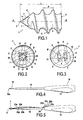
- La figure 1 est une vue schématique de côté de l'ancre vissable,
- La figure 2 est une vue schématique de face depuis l'avant de l'ancre de la figure 1,
- La figure 3 est une vue schématique de face depuis l'arrière de l'ancre de la figure 1,
- La figure 4 est une vue schématique de côté de l'outil d'insertion
- Et la figure 5 est une vue schématique de côté de l'outil d'insertion de la figure 4 sur lequel est positionnée l'ancre vissable.
- L'ancre vissable 1 est destinée à être implantée dans une partie osseuse pour assurer la fixation d'au moins un fil de suture, ayant sa fonction propre liée au geste chirurgical auquel il est associé. L'implantation de l'ancre doit être suffisamment solide pour ne pas courir le risque d'une extraction de l'ancre de la partie osseuse lors de la mise en tension du fil de suture. Néanmoins la longueur de l'ancre est suffisamment réduite pour permettre son implantation dans les fragments osseux de petites dimensions.
- Dans le mode préféré de réalisation qui est illustré à la figure 1, l'ancre 1 a une longueur totale L, entre sa face proximale 2 et sa pointe distale 3 qui est de l'ordre de 10 à 12 mm.
- L'ancre 1 est une pièce monobloc présentant un corps cylindrique 4 sur la périphérie duquel est prévu un filetage 5 s'étendant depuis la face proximale 2 jusqu'à la partie distale 6 de forme globalement conique terminée par la pointe distale 3, passant par l'axe longitudinal AA' de l'ancre 1.
- L'ancre 1 est percée de deux jeux d'évidement longitudinaux, respectivement 7, 7' pour le premier jeu 8 et 9,9' pour le second jeu 10. Chaque évidement longitudinal 7,7', 9,9' est un trou cylindrique, parallèle à l'axe AA' , débouchant à la fois dans la face proximale 2 et dans la partie distale conique 6. Chaque jeu 8,10 sert au passage d'un seul fil de suture.
- Au niveau de la partie distale conique d'extrémité 6, les deux évidements longitudinaux 7,7' du même jeu 8 sont reliés l'un à l'autre par une rainure 11 en creux dont la profondeur est supérieure au diamètre du fil de suture destiné à être utilisé avec ladite ancre 1. Cette disposition particulière vise à ce que le fil de suture, une fois enfilé dans les deux évidements longitudinaux 7,7' du même jeu 8, et mis sous tension depuis l'arrière de l'ancre 1, ledit fil ne dépasse pas de la surface extérieure de la partie distale conique 6. Le même fil de suture passe d'un premier évidement longitudinal 7 au deuxième évidement longitudinal 7' du même jeu 8 en formant une courbe qui pénètre dans la rainure de liaison 11, tandis que les deux brins libres dudit fil dépassent de la face proximale 2 et sont donc accessibles au praticien.
- Dans l'exemple préféré, les deux jeux 8, 10, comportant chacun deux évidements longitudinaux respectivement 7,7' et 9,9', sont disposés symétriquement par rapport à un plan médian passant par l'axe longitudinal AA' de l'ancre 1. Plus précisément, chaque évidement longitudinal est centré sur les quatre coins d'un carré BCDE, lui-même centré sur l'axe longitudinal AA' de l'ancre (figure 3). Lors de la mise en tension des brins libres des deux fils de suture, il y a un parfait équilibrage des forces de traction mises en jeu, du fait en particulier de cette disposition parfaitement symétrique.
- Comme cela apparaît à l'examen de la figure 2, le fond de la rainure 11, creusée dans la partie distale conique 6 en vue de relier l'un à l'autre les deux évidements longitudinaux 7, 7', est légèrement incurvé, formant un bord arrondi 12 de manière à éviter un coincement ou une usure du fil de suture lors de son coulissement à l'intérieur de l'ancre.
- Dans l'exemple illustré, pour une longueur totale L faisant 10mm, le pas P du filetage est de 2,5mm, ledit filetage faisant globalement 2,5 spires de 360° entre la face d'extrémité proximale 2 et la partie distale conique 6. Le diamètre maximal de l'ancre, au niveau du filetage 5, est de l'ordre de 5,7 mm. Le diamètre de la face d'extrémité proximale 2 est de l'ordre de 3,5 mm. Chaque évidement longitudinal 7,7', 9,9' a un diamètre de l'ordre de 0,9 mm. Ce diamètre convient aux fils de suture les plus courants dans le domaine, faisant de l'ordre de 0,4 à 0,7 mm.
- L'implantation de l'ancre 1 dans la partie osseuse est réalisée grâce à un outil d'insertion 16, assimilable à un tournevis spécialisé, avec un manche 13 et une tige 14 terminée par une tête 15 ayant une configuration adaptée pour venir se bloquer dans une empreinte 17 formée dans le corps cylindrique 4 à partir de la face d'extrémité proximale 2.
- Dans l'exemple illustré à la figure 2, cette empreinte 17 a, en section transversale, la forme d'une étoile à quatre branches 18,19,20,21, axée sur l'axe AA' longitudinal de l'ancre 1. La configuration de cette empreinte, en creux dans l'ancre 1, se trouve à l'identique sur la tête 15 de l'outil d'insertion 16, mais en saillie de manière à ce que la tête 15 puisse venir se loger de manière ajustée dans l'empreinte 17. Pour faciliter l'introduction de l'extrémité 15a de la tête 15, l'empreinte 17 et la tête 15 ont un profil légèrement incliné vers l'avant, de sorte que l'extrémité 15a de la tête 15 est de dimension plus réduite que l'empreinte 17 au niveau de la face d'extrémité proximale 2.
- La configuration en étoile à quatre branches pour l'empreinte 17 permet une très bonne localisation de ladite empreinte entre les quatre évidements longitudinaux 7,7', 9,9', comme cela apparaît à l'examen de la figure 3. Les quatre branches 18, 19, 20, 21 de l'étoile viennent se loger dans l'espace entre les deux évidements longitudinaux, respectivement 7,7' pour la première branche 18, 7',9' pour la deuxième branche 19, 9', 9 pour la troisième branche 20 et 9,7 pour la quatrième branche 21. L'empreinte 17 est donc totalement indépendante des évidements longitudinaux 7,7', 9,9' de telle sorte qu'il n'y a aucun contact entre la tête 15 de l'outil d'insertion 16 avec les deux fils de suture enfilés dans l'ancre 1.
- La longueur de l'empreinte à l'intérieur du corps cylindrique 4 est suffisamment importante pour garantir le vissage sans problème de l'ancre 1 dans la partie osseuse. Dans l'exemple précis donné ci-dessus, à titre non exhaustif, cette longueur est de 5,5 mm, avec un angle d'inclinaison de l'ordre de 2°.
- L'angle au sommet de la partie distale conique 6 est de l'ordre de 70°.
- Sur la figure 5 on a représenté l'ancre 1 montée sur la tête 15 de l'outil d'insertion 16, avec les deux fils de suture 22, 23 dont les deux brins libres 22a, 22b, 23a, 23b sont réunis et bloqués contre la tige 14 de l'outil 17 grâce à une pièce 24 de blocage, venant s'emboîter sur ladite tige par-dessus les deux fils 22, 23. Cette pièce 24 n'empêche pas le libre coulissement d'un fil de suture le long de la tige 14 et à l'intérieur de l'ancre 1 lors de la mise en tension dudit fil de suture, notamment lorsque le praticien tire sur l'un des brins dudit fil.
- On comprend que la tête 15 est particulièrement adaptée à une empreinte 17 donnée. L'ensemble chirurgical mis à la disposition du praticien peut comprendre plusieurs ancres 1 de tailles différentes suivant les applications, toutes comportant la même empreinte 17. Dans ce cas le praticien peut utiliser le même outil d'insertion 16 avec la même tige 14 et la même tête 15. Cependant il peut être préférable d'adapter l'empreinte 17 à la taille de l'ancre 1 et par conséquent de disposer d'un outil d'insertion 16 qui soit parfaitement adapté à chaque empreinte. Dans ce cas, de préférence, il y a autant de tiges 14 que de sortes d'empreintes, mais un seul manche 16 apte à coopérer, pour le vissage, avec l'extrémité proximale de toutes lesdites tiges 14.
- L'ancre 1 peut être métallique, dans un matériau biocompatible conventionnel. Elle peut également être dans un matériau biodégradable ou résorbable, stérilisable, d'origine naturelle ou synthétique, notamment un matériau choisi dans le groupe suivant :
- polylactide, polyglycolide, poly-ε-caprolactone,
- polyhydroxy butyrate, polyhydroxy valérate,
- poly carbonates et assimilés,
- cellulose, polysaccharides, amidon,
- De préférence, dans ce cas, le matériau biodégradable ou résorbable contient une charge, sous forme de poudre ou de nano poudre dans une proportion de 5 à 60%, ladite charge étant notamment choisie dans le groupe : hydroxy apatite et/ou de phosphate de calcium, notamment de β tricalcium phosphate, et/ou d'hydrogéno phosphate de calcium et/ou de carbonate de calcium et/ou d'hydrogéno carbonate de calcium, de préférence à raison de 5 à 60% en poids de charge.
- Le choix du matériau biodégradable ou résorbable ainsi que le choix de la charge permet d'ajuster l'élimination de l'ancre et son remplacement par une partie osseuse régénérée dans une durée qu'il est possible de déterminer, notamment en terme d'évolution des propriétés mécanique. Par exemple les propriétés mécaniques , en terme de force de rupture de l'ancre, pourront évoluer avec une paire de l'ordre de 50% des propriétés initiales au bout de six mois et une perte totale des propriétés initiales au bout d'un an.
Claims (9)
- Elément d'ancrage (1) de fil de suture formé d'un corps monobloc fileté extérieurement présentant une partie distale, une face d'extrémité proximale (2), et deux évidements longitudinaux, traversant ledit corps et débouchant d'une part dans la face d'extrémité proximale et d'autre part dans la partie distale caractérisé en ce que :- la partie distale (6) est de forme conique, avec une pointe d'extrémité (3) selon l'axe longitudinal (AA') de l'élément (1), et en ce que, les deux évidements longitudinaux débouchant, de façon excentrée par rapport à l'extrémité en pointe, la partie distale conique (6) comporte une rainure de liaison (11), reliant les deux évidements longitudinaux (7,7'), ayant une profondeur supérieure au diamètre du fil de suture ;- l'élément d'ancrage comporte une empreinte en creux (17) pour le placement d'une tête (15) de l'outil d'insertion (16) indépendante des évidements longitudinaux (7,7').W
- Elément d'ancrage selon la revendication 1 caractérisée en ce qu'elle comporte deux jeux (8,10) de deux évidements longitudinaux (7,7', 9,9') reliés par une rainure de liaison (11), formée dans la partie distale conique (6).
- Elément d'ancrage selon la revendication 2 caractérisée en ce que les deux jeux (8,10) sont disposés symétriquement par rapport à un plan médian longitudinal de symétrie.
- Elément d'ancrage selon la revendication 3 caractérisée en ce que les quatre évidements longitudinaux (7,7',9,9') sont disposés, en section transversale, selon les quatre angles (B,C,D,E) d'un carré ayant pour axe de symétrie l'axe longitudinal (AA') de l'élément.
- Elément d'ancrage selon l'une des revendications 1 à 4 caractérisée en ce qu'il est formé dans un matériau résorbable, stérilisable, d'origine naturelle ou synthétique, notamment choisi dans le groupe :- polylactide, polyglycolide, poly-ε-caprolactone,- polyhydroxy butyrate, polyhydroxy valérate,- poly carbonates et assimilés,- cellulose, polysaccharides, amidon,leurs homopolymères, leurs copolymères et leurs dérivés.
- Elément d'ancrage selon la revendication 5 caractérisée en ce que le matériau est chargé de poudre et/ou de nano poudre, notamment d'un composant choisi dans le groupe : hydroxy apatite et/ou de phosphate de calcium, notamment de β tricalcium phosphate, et/ou d'hydrogéno phosphate de calcium et/ou de carbonate de calcium et/ou d'hydrogéno carbonate de calcium, de préférence à raison de 5 à 60% en poids de charge.
- Ensemble chirurgical comportant au moins un élément d'ancrage (1) selon l'une des revendications 1 à 6 et un outil d'insertion (16) spécialement adapté pour réaliser le vissage dudit élément (1) caractérisé en ce que la face d'extrémité proximale (2) de l'élément d'ancrage (1) comporte une empreinte en creux (17) pour le placement ajusté de la tête (15) de l'outil d'insertion (16).
- Ensemble selon la revendication 7 caractérisé en ce que l'empreinte (17) en creux a une configuration polygonale, notamment très légèrement inclinée vers l'avant de l'élément.
- Ensemble selon la revendication 8 caractérisé en ce que l'empreinte (17) a une configuration en étoile à quatre branches, chacune desdites branches (18,19,20,21) venant se loger dans l'espace entre deux évidements longitudinaux adjacents.
Applications Claiming Priority (1)
| Application Number | Priority Date | Filing Date | Title |
|---|---|---|---|
| FR0605607A FR2902635B1 (fr) | 2006-06-22 | 2006-06-22 | Element d'ancrage de fil de soudure |
Publications (2)
| Publication Number | Publication Date |
|---|---|
| EP1870041A2 true EP1870041A2 (fr) | 2007-12-26 |
| EP1870041A3 EP1870041A3 (fr) | 2009-07-29 |
Family
ID=37726540
Family Applications (1)
| Application Number | Title | Priority Date | Filing Date |
|---|---|---|---|
| EP07110801A Withdrawn EP1870041A3 (fr) | 2006-06-22 | 2007-06-21 | Elément d'ancrage de fil de suture |
Country Status (2)
| Country | Link |
|---|---|
| EP (1) | EP1870041A3 (fr) |
| FR (1) | FR2902635B1 (fr) |
Cited By (1)
| Publication number | Priority date | Publication date | Assignee | Title |
|---|---|---|---|---|
| CN105534580A (zh) * | 2016-01-28 | 2016-05-04 | 苏州瑞华医院有限公司 | 一种张力空心螺钉 |
Family Cites Families (4)
| Publication number | Priority date | Publication date | Assignee | Title |
|---|---|---|---|---|
| DE29717413U1 (de) * | 1997-09-30 | 1999-02-04 | Degima Medizinprodukte Dr Dr T | Fadenanker aus resorbierbarem Kunststoff |
| US6165203A (en) * | 1998-09-11 | 2000-12-26 | Bio Innovation, Ltd. | Suture anchor installation devices and methods |
| US6685728B2 (en) * | 2002-01-25 | 2004-02-03 | Stryker Endoscopy | Threaded suture anchor and method of use |
| US8579940B2 (en) * | 2004-04-06 | 2013-11-12 | Arthrex, Inc. | Suture anchor with apertures at tip |
-
2006
- 2006-06-22 FR FR0605607A patent/FR2902635B1/fr not_active Expired - Fee Related
-
2007
- 2007-06-21 EP EP07110801A patent/EP1870041A3/fr not_active Withdrawn
Non-Patent Citations (1)
| Title |
|---|
| None |
Cited By (1)
| Publication number | Priority date | Publication date | Assignee | Title |
|---|---|---|---|---|
| CN105534580A (zh) * | 2016-01-28 | 2016-05-04 | 苏州瑞华医院有限公司 | 一种张力空心螺钉 |
Also Published As
| Publication number | Publication date |
|---|---|
| FR2902635B1 (fr) | 2009-10-30 |
| FR2902635A1 (fr) | 2007-12-28 |
| EP1870041A3 (fr) | 2009-07-29 |
Similar Documents
| Publication | Publication Date | Title |
|---|---|---|
| EP2088935B1 (fr) | Implant d'ancrage et de fixation et ensemble chirurgical pour son implantation | |
| EP2481376B1 (fr) | Implant glénoïdien pour prothèse d'épaule et kit chirurgical | |
| EP0348272B1 (fr) | Implant pour dispositif d'ostéosynthèse rachidienne, notamment en traumatologie | |
| EP0825838B1 (fr) | Equipement chirurgical d'implantologie dentaire et elements, implant dentaire et instruments de forage, constitutifs | |
| EP2363078B1 (fr) | Implant de suture | |
| EP2393441B1 (fr) | Vis d'osteosynthese et d'arthrodese | |
| EP0858300A1 (fr) | Dispositif d'ancrage ligamentaire | |
| EP1632199A1 (fr) | Implant de fixation d'un greffon osseux au sein d'une articulation en vue d'assurer l'arthrodèse de l'articulation | |
| EP1870050A2 (fr) | Ensemble chirurgical pour la reperation osseuse comprenant une vis cylindrique du type vis de Herbert | |
| EP0180532B1 (fr) | Coapteur pour fractures du col du fémur et similaires | |
| EP0844849B1 (fr) | Cheville intrafocale | |
| EP4132415B1 (fr) | Implant d'ancrage osseux à expansion optimisée | |
| WO2021204951A1 (fr) | Implant d'ancrage osseux à stabilisation corticale | |
| EP0830097A1 (fr) | Bague d'osteosynthese utilisable en combinaison avec une broche ou une vis, et ancillaire pour sa mise en compression | |
| EP1870041A2 (fr) | Elément d'ancrage de fil de suture | |
| WO2013175099A1 (fr) | Vis autocompressive d'osteosynthese | |
| FR2859904A1 (fr) | Perfectionnement aux dispositifs d'osteosynthese de type vis, broche ou similaire | |
| FR2642641A1 (fr) | Agrafe chirurgicale | |
| EP0278887B1 (fr) | Implant intraosseux pour la fixation de prothèses | |
| WO2002065929A1 (fr) | Vis de fixation | |
| EP1560534B1 (fr) | Dispositif d osteosynthese epiphysaire en deux parties, notamment pour clou ou plaque | |
| FR2879916A1 (fr) | Prothese de hanche | |
| FR2922751A1 (fr) | Implant dentaire et outil pour la preparation de la zone d'implantation. | |
| FR2945437A1 (fr) | Vis et tournevis pour son vissage | |
| FR2864889A1 (fr) | Materiel d'osteosynthese ou prothetique, notamment vis et clou |
Legal Events
| Date | Code | Title | Description |
|---|---|---|---|
| PUAI | Public reference made under article 153(3) epc to a published international application that has entered the european phase |
Free format text: ORIGINAL CODE: 0009012 |
|
| AK | Designated contracting states |
Kind code of ref document: A2 Designated state(s): AT BE BG CH CY CZ DE DK EE ES FI FR GB GR HU IE IS IT LI LT LU LV MC MT NL PL PT RO SE SI SK TR |
|
| AX | Request for extension of the european patent |
Extension state: AL BA HR MK YU |
|
| PUAL | Search report despatched |
Free format text: ORIGINAL CODE: 0009013 |
|
| AK | Designated contracting states |
Kind code of ref document: A3 Designated state(s): AT BE BG CH CY CZ DE DK EE ES FI FR GB GR HU IE IS IT LI LT LU LV MC MT NL PL PT RO SE SI SK TR |
|
| AX | Request for extension of the european patent |
Extension state: AL BA HR MK RS |
|
| 17P | Request for examination filed |
Effective date: 20100125 |
|
| 17Q | First examination report despatched |
Effective date: 20100224 |
|
| AKX | Designation fees paid |
Designated state(s): AT BE BG CH CY CZ DE DK EE ES FI FR GB GR HU IE IS IT LI LT LU LV MC MT NL PL PT RO SE SI SK TR |
|
| RAP1 | Party data changed (applicant data changed or rights of an application transferred) |
Owner name: ADVANCE |
|
| STAA | Information on the status of an ep patent application or granted ep patent |
Free format text: STATUS: THE APPLICATION IS DEEMED TO BE WITHDRAWN |
|
| 18D | Application deemed to be withdrawn |
Effective date: 20160105 |