EP1870310A2 - Klemmgabel und Verfahren zur Herstellung einer Klemmgabel - Google Patents
Klemmgabel und Verfahren zur Herstellung einer Klemmgabel Download PDFInfo
- Publication number
- EP1870310A2 EP1870310A2 EP07075475A EP07075475A EP1870310A2 EP 1870310 A2 EP1870310 A2 EP 1870310A2 EP 07075475 A EP07075475 A EP 07075475A EP 07075475 A EP07075475 A EP 07075475A EP 1870310 A2 EP1870310 A2 EP 1870310A2
- Authority
- EP
- European Patent Office
- Prior art keywords
- aperture
- base portion
- axis
- bolt hole
- slot
- Prior art date
- Legal status (The legal status is an assumption and is not a legal conclusion. Google has not performed a legal analysis and makes no representation as to the accuracy of the status listed.)
- Granted
Links
- 238000000034 method Methods 0.000 title claims abstract description 17
- 238000005520 cutting process Methods 0.000 claims description 5
- 238000005553 drilling Methods 0.000 description 5
- 230000000694 effects Effects 0.000 description 2
- 238000004519 manufacturing process Methods 0.000 description 2
Images
Classifications
-
- B—PERFORMING OPERATIONS; TRANSPORTING
- B62—LAND VEHICLES FOR TRAVELLING OTHERWISE THAN ON RAILS
- B62D—MOTOR VEHICLES; TRAILERS
- B62D1/00—Steering controls, i.e. means for initiating a change of direction of the vehicle
- B62D1/02—Steering controls, i.e. means for initiating a change of direction of the vehicle vehicle-mounted
- B62D1/16—Steering columns
-
- B—PERFORMING OPERATIONS; TRANSPORTING
- B62—LAND VEHICLES FOR TRAVELLING OTHERWISE THAN ON RAILS
- B62D—MOTOR VEHICLES; TRAILERS
- B62D1/00—Steering controls, i.e. means for initiating a change of direction of the vehicle
- B62D1/02—Steering controls, i.e. means for initiating a change of direction of the vehicle vehicle-mounted
- B62D1/16—Steering columns
- B62D1/20—Connecting steering column to steering gear
-
- F—MECHANICAL ENGINEERING; LIGHTING; HEATING; WEAPONS; BLASTING
- F16—ENGINEERING ELEMENTS AND UNITS; GENERAL MEASURES FOR PRODUCING AND MAINTAINING EFFECTIVE FUNCTIONING OF MACHINES OR INSTALLATIONS; THERMAL INSULATION IN GENERAL
- F16D—COUPLINGS FOR TRANSMITTING ROTATION; CLUTCHES; BRAKES
- F16D1/00—Couplings for rigidly connecting two coaxial shafts or other movable machine elements
- F16D1/06—Couplings for rigidly connecting two coaxial shafts or other movable machine elements for attachment of a member on a shaft or on a shaft-end
- F16D1/08—Couplings for rigidly connecting two coaxial shafts or other movable machine elements for attachment of a member on a shaft or on a shaft-end with clamping hub; with hub and longitudinal key
- F16D1/0852—Couplings for rigidly connecting two coaxial shafts or other movable machine elements for attachment of a member on a shaft or on a shaft-end with clamping hub; with hub and longitudinal key with radial clamping between the mating surfaces of the hub and shaft
- F16D1/0864—Couplings for rigidly connecting two coaxial shafts or other movable machine elements for attachment of a member on a shaft or on a shaft-end with clamping hub; with hub and longitudinal key with radial clamping between the mating surfaces of the hub and shaft due to tangential loading of the hub, e.g. a split hub
-
- F—MECHANICAL ENGINEERING; LIGHTING; HEATING; WEAPONS; BLASTING
- F16—ENGINEERING ELEMENTS AND UNITS; GENERAL MEASURES FOR PRODUCING AND MAINTAINING EFFECTIVE FUNCTIONING OF MACHINES OR INSTALLATIONS; THERMAL INSULATION IN GENERAL
- F16D—COUPLINGS FOR TRANSMITTING ROTATION; CLUTCHES; BRAKES
- F16D3/00—Yielding couplings, i.e. with means permitting movement between the connected parts during the drive
- F16D3/16—Universal joints in which flexibility is produced by means of pivots or sliding or rolling connecting parts
- F16D3/26—Hooke's joints or other joints with an equivalent intermediate member to which each coupling part is pivotally or slidably connected
- F16D3/38—Hooke's joints or other joints with an equivalent intermediate member to which each coupling part is pivotally or slidably connected with a single intermediate member with trunnions or bearings arranged on two axes perpendicular to one another
- F16D3/382—Hooke's joints or other joints with an equivalent intermediate member to which each coupling part is pivotally or slidably connected with a single intermediate member with trunnions or bearings arranged on two axes perpendicular to one another constructional details of other than the intermediate member
- F16D3/387—Fork construction; Mounting of fork on shaft; Adapting shaft for mounting of fork
-
- F—MECHANICAL ENGINEERING; LIGHTING; HEATING; WEAPONS; BLASTING
- F16—ENGINEERING ELEMENTS AND UNITS; GENERAL MEASURES FOR PRODUCING AND MAINTAINING EFFECTIVE FUNCTIONING OF MACHINES OR INSTALLATIONS; THERMAL INSULATION IN GENERAL
- F16B—DEVICES FOR FASTENING OR SECURING CONSTRUCTIONAL ELEMENTS OR MACHINE PARTS TOGETHER, e.g. NAILS, BOLTS, CIRCLIPS, CLAMPS, CLIPS OR WEDGES; JOINTS OR JOINTING
- F16B2/00—Friction-grip releasable fastenings
- F16B2/02—Clamps, i.e. with gripping action effected by positive means other than the inherent resistance to deformation of the material of the fastening
- F16B2/06—Clamps, i.e. with gripping action effected by positive means other than the inherent resistance to deformation of the material of the fastening external, i.e. with contracting action
- F16B2/065—Clamps, i.e. with gripping action effected by positive means other than the inherent resistance to deformation of the material of the fastening external, i.e. with contracting action using screw-thread elements
-
- Y—GENERAL TAGGING OF NEW TECHNOLOGICAL DEVELOPMENTS; GENERAL TAGGING OF CROSS-SECTIONAL TECHNOLOGIES SPANNING OVER SEVERAL SECTIONS OF THE IPC; TECHNICAL SUBJECTS COVERED BY FORMER USPC CROSS-REFERENCE ART COLLECTIONS [XRACs] AND DIGESTS
- Y10—TECHNICAL SUBJECTS COVERED BY FORMER USPC
- Y10T—TECHNICAL SUBJECTS COVERED BY FORMER US CLASSIFICATION
- Y10T403/00—Joints and connections
- Y10T403/53—Split end with laterally movable opposed portions
- Y10T403/535—Split end with laterally movable opposed portions with separate force-applying means
-
- Y—GENERAL TAGGING OF NEW TECHNOLOGICAL DEVELOPMENTS; GENERAL TAGGING OF CROSS-SECTIONAL TECHNOLOGIES SPANNING OVER SEVERAL SECTIONS OF THE IPC; TECHNICAL SUBJECTS COVERED BY FORMER USPC CROSS-REFERENCE ART COLLECTIONS [XRACs] AND DIGESTS
- Y10—TECHNICAL SUBJECTS COVERED BY FORMER USPC
- Y10T—TECHNICAL SUBJECTS COVERED BY FORMER US CLASSIFICATION
- Y10T403/00—Joints and connections
- Y10T403/70—Interfitted members
- Y10T403/7026—Longitudinally splined or fluted rod
Definitions
- the present invention relates to a clamp yoke for providing a pivotable connection between two rotatable shafts, and to method of forming such a clamp yoke.
- the clamp yoke on a steering column or I-shaft of a motor vehicle is intended to transmit the steering torque to the pinion for the life of the vehicle, and without lash.
- These requirements can be problematic, especially in the case where electric power steering is used, and where the connection with the pinions is by serrations.
- Design limitations include bolt tightening torque (limited by material characteristics and the need to avoid thread stripping); and minimum/maximum lash between the yoke and pinion (the minimum lash has to guarantee the assembly and so the maximum lash is given by minimum lash plus feasible tolerances for yoke and pinion interface). The worst case is given by lower limit of bolt tightening torque and the upper limit of the lash between the yoke and the pinion.
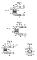
- FIGs 1 through 4 illustrate known arrangements for trying to overcome the above mentioned problems.
- Each of these illustrated arrangements show a clamp yoke 10 having a substantially U-shaped profile and comprising a base portion 12 and a pair of ear portions 14, 16.
- Axially aligned holes 18 are formed in the ear portions 14, 16.
- a serrated aperture 20 is formed in the base portion 12.
- a bolt hole 22 is formed in the base portion 12 adjacent the aperture 20.
- a slot 24 is cut from one end 26 of the base portion 12 to extend through the bolt hole 22 and open into the aperture 20.
- an additional hole 28 is drilled in one ear portion 14 of the yoke 10 at the end of the slot 24 to move the "hinge" as far as possible from the bolt hole 22.
- the elasticity of the yoke 10 on the other end 30 of the base portion 12 to the bolt hole 22 is improved, as shown in Figure 2, by producing an asymmetric yoke 10 by reducing the amount of material on the other end 30 of the base portion 12.
- the elasticity of the yoke 10 is improved by drilling an axial hole 32 in the base portion 12 on the opposite side of the aperture 20 to the bolt hole 22, and then ensuring that the axial hole opens 34 into the aperture during a subsequent broaching operation, as shown in Figures 3 and 4.
- the present invention also includes a method of forming a clamp yoke for providing a pivotable connection between two rotatable shafts, the method comprising the steps of cold forming a part having a substantially symmetrical U-shaped profile from a metallic blank, the part having a base portion and an ear portion at each end of the base portion; forming axially aligned holes in the ear portions; forming an aperture in the base portion, the aperture having an axis which is substantially perpendicular to the axis of the holes in the ear portions; forming a bolt hole in the base portion adjacent one side of the aperture, the bolt hole having an axis which is substantially perpendicular to the axis of the aperture and the axis of the holes in the ear portions; and cutting a slot in the base portion, the slot extending from one end of the base portion, through the bolt hole and the aperture and into the base portion on the opposite side of the aperture to the bolt hole.
- the present invention provides a clamp yoke which is easier and cheaper to manufacture than prior known arrangements, as well as providing the required elasticity of the yoke alongside the required clamping efficiency.
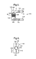
- the clamp yoke 110 in accordance with the present invention comprises a base portion 112 and a pair of ear portions 114, 116.
- the yoke 110 has a substantially symmetrical U-shaped profile, and the ear portions 114, 116 extend from opposite ends 126, 130 of the base portion 112.
- Each ear portion 114, 116 has a hole 118, wherein the holes in each ear portion are substantially axially aligned on a first axis A.
- the base portion 112 has an aperture 120, wherein the aperture has an axis B which is substantially perpendicular to the first axis A.
- the base portion 112 also has a bolt hole 122 adjacent one side of the aperture 120, wherein the bolt hole has an axis C which is substantially perpendicular to the aperture axis B and to the first axis A.
- the base portion 112 has a slot 124 extending from one end 126 of the base portion, through the bolt hole 122 and the aperture 120, and into the base portion on the opposite side of the aperture to the bolt hole, in a direction towards the other end 130 of the base portion.
- the slot 124 preferably extends a predetermined distance X beyond the aperture 120 towards said other end 130.
- the slot 124 extends into the ear portion 114 at said one end 126 of the base portion 112.
- the slot 124 preferably lies in a plane which extends substantially perpendicular to the axis C of the bolt hole 122, that is, a plane which substantially aligns with and contains the aperture axis B and the first axis A.
- the slot 124 has been formed by a cutting operation, preferably in a single cutting operation, and preferably using a substantially circular saw blade.
- the method of forming the clamp yoke 110 comprises the steps of cold forming a part having a substantially symmetrical U-shaped profile from a metallic blank, the part having the base portion 112 and the pair of ear portions 114, 116.
- the cold forming step may be performed in a single operation, but is preferably performed in several separate operations.
- the axially aligned holes 118 are formed in the ear portions 114, 116, preferably by a drilling operation.
- the aperture 120 is formed in the base portion 112, preferably initially by broaching during the cold forming step.
- the axis B of the aperture 120 is substantially perpendicular to the first axis A, the aligned axis of the holes 118 in the ear portions 114, 116.
- the aperture 120 is preferably formed with serrations 136 in the surface thereof, the serrations extending in a direction which is substantially parallel to the direction of the aperture axis B.
- the bolt hole 122 is formed, preferably by drilling, in the base portion 112 adjacent one side of the aperture 120, and preferably substantially tangential thereto.
- the axis C of the bolt hole 122 is substantially perpendicular to the aperture axis B and the first axis A.
- the slot 124 is cut in the base portion 112, preferably in a single operation, and preferably using a substantially circular saw blade. The slot 124 extends from said one end 126 of the base portion 112, through the bolt hole 122 and the aperture 120, and into the base portion on the opposite side of the aperture to the bolt hole.
- the present invention uses a symmetric cold formed yoke which is cheaper than using an asymmetric yoke.
- the present invention also avoids the need for additional drilling operations (as required by the prior art of Figures 1 to 4) which also reduces costs.
- the present invention optimises the sawing operation, and a smaller sawing tool can be used which is compatible with the shape of the clamp yoke.
- the base portion of the clamp yoke is also sawn in the area which is on the opposite side of the aperture to the bolt hole. In this way, the vertical hole 28 in the ear portion of the prior art ( Figures 1 through 4) is no longer needed because the surface that is created by the slot creates substantially the same effect.
- the horizontal hole 32 in the base portion of the prior art ( Figures 3 and 4) can be avoided because the slot extension creates a hinge effect in the base portion thereby creating the desired elasticity.
- the removal of material from the other end 30 of the base portion ( Figure 2) is no longer required because the slot extension creates the desired elasticity. In this way, the cost of drilling two holes is saved, the cost of removal of material is avoided, and the overall manufacturing steps are easier.
Landscapes
- Engineering & Computer Science (AREA)
- Mechanical Engineering (AREA)
- General Engineering & Computer Science (AREA)
- Chemical & Material Sciences (AREA)
- Combustion & Propulsion (AREA)
- Transportation (AREA)
- Clamps And Clips (AREA)
- Forklifts And Lifting Vehicles (AREA)
- Particle Accelerators (AREA)
- Load-Engaging Elements For Cranes (AREA)
- Gripping Jigs, Holding Jigs, And Positioning Jigs (AREA)
- Mutual Connection Of Rods And Tubes (AREA)
Applications Claiming Priority (1)
| Application Number | Priority Date | Filing Date | Title |
|---|---|---|---|
| GBGB0612314.5A GB0612314D0 (en) | 2006-06-21 | 2006-06-21 | Clamp yoke |
Publications (3)
| Publication Number | Publication Date |
|---|---|
| EP1870310A2 true EP1870310A2 (de) | 2007-12-26 |
| EP1870310A3 EP1870310A3 (de) | 2008-12-03 |
| EP1870310B1 EP1870310B1 (de) | 2010-08-11 |
Family
ID=36803641
Family Applications (1)
| Application Number | Title | Priority Date | Filing Date |
|---|---|---|---|
| EP07075475A Not-in-force EP1870310B1 (de) | 2006-06-21 | 2007-06-15 | Klemmgabel und Verfahren zur Herstellung einer Klemmgabel |
Country Status (5)
| Country | Link |
|---|---|
| US (1) | US8262309B2 (de) |
| EP (1) | EP1870310B1 (de) |
| AT (1) | ATE477158T1 (de) |
| DE (1) | DE602007008324D1 (de) |
| GB (1) | GB0612314D0 (de) |
Families Citing this family (8)
| Publication number | Priority date | Publication date | Assignee | Title |
|---|---|---|---|---|
| DE102011050748B3 (de) * | 2011-05-31 | 2012-07-12 | Thyssenkrupp Presta Aktiengesellschaft | Verbindung eines Wellenstücks einer Lenkwelle für ein Kraftfahrzeug mit einem Anschlussteil |
| FR2979403B1 (fr) * | 2011-08-31 | 2014-02-14 | Zf Systemes De Direction Nacam Sas | Dispositif de liaison d'une colonne de direction avec un boitier de direction. |
| JP5790491B2 (ja) * | 2011-12-28 | 2015-10-07 | 日本精工株式会社 | 中間シャフト |
| FR2997142B1 (fr) * | 2012-10-18 | 2014-12-05 | Epsilon Composite | Procede de realisation d'un embout goupille d'une piece longitudinale, embout ainsi obtenu |
| US10480553B2 (en) * | 2017-10-06 | 2019-11-19 | Steering Solutions Ip Holding Corporation | Shaft assembly |
| JP6613289B2 (ja) * | 2017-11-21 | 2019-11-27 | ファナック株式会社 | カップリングの固定方法 |
| US10933525B2 (en) * | 2018-07-04 | 2021-03-02 | Fanuc Corporation | Horizontal articulated robot |
| US11305808B2 (en) * | 2020-06-22 | 2022-04-19 | Steering Solutions Ip Holding Corporation | Steering shaft clamp yoke with bolt blocking component |
Citations (1)
| Publication number | Priority date | Publication date | Assignee | Title |
|---|---|---|---|---|
| FR2857888A1 (fr) | 2003-07-21 | 2005-01-28 | Euroform Srl | Procede de fabrication d'un element de couplage, en particulier d'une fourche pour joints de cardan, et element de couplage ainsi obtenu |
Family Cites Families (4)
| Publication number | Priority date | Publication date | Assignee | Title |
|---|---|---|---|---|
| US1830976A (en) * | 1928-07-28 | 1931-11-10 | George B Ashworth | Eccentric crank |
| US4068965A (en) * | 1976-11-08 | 1978-01-17 | Craneveyor Corporation | Shaft coupling |
| DE3522487A1 (de) * | 1985-06-22 | 1987-01-02 | Schmidt Kupplung Gmbh | Kupplung zum kuppeln umlaufender maschinenteile |
| DE9404853U1 (de) * | 1994-03-22 | 1994-07-28 | Ktr Kupplungstechnik Gmbh, 48432 Rheine | Kupplungsnabe mit profilierter Nabenbohrung |
-
2006
- 2006-06-21 GB GBGB0612314.5A patent/GB0612314D0/en not_active Ceased
-
2007
- 2007-06-15 DE DE602007008324T patent/DE602007008324D1/de active Active
- 2007-06-15 AT AT07075475T patent/ATE477158T1/de not_active IP Right Cessation
- 2007-06-15 EP EP07075475A patent/EP1870310B1/de not_active Not-in-force
- 2007-06-21 US US11/821,098 patent/US8262309B2/en active Active
Patent Citations (1)
| Publication number | Priority date | Publication date | Assignee | Title |
|---|---|---|---|---|
| FR2857888A1 (fr) | 2003-07-21 | 2005-01-28 | Euroform Srl | Procede de fabrication d'un element de couplage, en particulier d'une fourche pour joints de cardan, et element de couplage ainsi obtenu |
Also Published As
| Publication number | Publication date |
|---|---|
| US20070298889A1 (en) | 2007-12-27 |
| ATE477158T1 (de) | 2010-08-15 |
| US8262309B2 (en) | 2012-09-11 |
| DE602007008324D1 (de) | 2010-09-23 |
| EP1870310A3 (de) | 2008-12-03 |
| GB0612314D0 (en) | 2006-08-02 |
| EP1870310B1 (de) | 2010-08-11 |
Similar Documents
| Publication | Publication Date | Title |
|---|---|---|
| EP1870310A2 (de) | Klemmgabel und Verfahren zur Herstellung einer Klemmgabel | |
| CN101860093B (zh) | 用于电动机的隔离环 | |
| US5749689A (en) | Drill, particulary drilling screw | |
| CN101821904B (zh) | 电气装置 | |
| EP0958088A1 (de) | Zahnstruktur eines bandsägeblattes | |
| EP3293860A1 (de) | Rotierender elektrischer rotor und verfahren zur herstellung des rotierenden elektrischen rotors | |
| CN102734526A (zh) | 制冷系统及电动阀 | |
| CN101048600A (zh) | 紧固元件 | |
| EP2819818B1 (de) | Werkzeugmaschinentrennvorrichtung | |
| US10879761B2 (en) | Rotor and method of manufacturing the same | |
| US7931224B2 (en) | Round cutter-blade of a paper shredder | |
| CA2793494C (en) | Self-tapping screw | |
| JP2003237396A (ja) | Frp製プロペラシャフト | |
| EP2685025A1 (de) | Schraube zur Befestigung eines Dachelements eines Außenwandelements mit Dreischichtstruktur | |
| JP2010093997A (ja) | 積層鉄心の製造方法及び金型装置 | |
| KR100548964B1 (ko) | 바이트 결합을 위한 복합재료 공구용 바 | |
| EP2241768B1 (de) | Verfahren zur Herstellung einer Flanschdrillschraube | |
| JP4228063B2 (ja) | 特定の形状に成形された電流伝導体レールを備えた発火機械式の切断装置 | |
| CN112658594A (zh) | 横梁连接板的成型方法 | |
| WO2008040932A1 (en) | Mounting arrangement | |
| JP3140190U (ja) | カップリング | |
| US20100018276A1 (en) | Sheet metal rocker arm with integrally formed cross member | |
| US20070292233A1 (en) | Locking shear nut | |
| JP5045257B2 (ja) | 自在継手の加工方法 | |
| WO2003041920A2 (en) | A tool with vibration dampening means |
Legal Events
| Date | Code | Title | Description |
|---|---|---|---|
| PUAI | Public reference made under article 153(3) epc to a published international application that has entered the european phase |
Free format text: ORIGINAL CODE: 0009012 |
|
| AK | Designated contracting states |
Kind code of ref document: A2 Designated state(s): AT BE BG CH CY CZ DE DK EE ES FI FR GB GR HU IE IS IT LI LT LU LV MC MT NL PL PT RO SE SI SK TR |
|
| AX | Request for extension of the european patent |
Extension state: AL BA HR MK YU |
|
| PUAL | Search report despatched |
Free format text: ORIGINAL CODE: 0009013 |
|
| AK | Designated contracting states |
Kind code of ref document: A3 Designated state(s): AT BE BG CH CY CZ DE DK EE ES FI FR GB GR HU IE IS IT LI LT LU LV MC MT NL PL PT RO SE SI SK TR |
|
| AX | Request for extension of the european patent |
Extension state: AL BA HR MK RS |
|
| 17P | Request for examination filed |
Effective date: 20090603 |
|
| 17Q | First examination report despatched |
Effective date: 20090626 |
|
| AKX | Designation fees paid |
Designated state(s): AT BE BG CH CY CZ DE DK EE ES FI FR GB GR HU IE IS IT LI LT LU LV MC MT NL PL PT RO SE SI SK TR |
|
| GRAP | Despatch of communication of intention to grant a patent |
Free format text: ORIGINAL CODE: EPIDOSNIGR1 |
|
| GRAS | Grant fee paid |
Free format text: ORIGINAL CODE: EPIDOSNIGR3 |
|
| GRAA | (expected) grant |
Free format text: ORIGINAL CODE: 0009210 |
|
| AK | Designated contracting states |
Kind code of ref document: B1 Designated state(s): AT BE BG CH CY CZ DE DK EE ES FI FR GB GR HU IE IS IT LI LT LU LV MC MT NL PL PT RO SE SI SK TR |
|
| REG | Reference to a national code |
Ref country code: GB Ref legal event code: FG4D |
|
| REG | Reference to a national code |
Ref country code: CH Ref legal event code: EP |
|
| REG | Reference to a national code |
Ref country code: IE Ref legal event code: FG4D |
|
| REF | Corresponds to: |
Ref document number: 602007008324 Country of ref document: DE Date of ref document: 20100923 Kind code of ref document: P |
|
| REG | Reference to a national code |
Ref country code: NL Ref legal event code: VDEP Effective date: 20100811 |
|
| RAP2 | Party data changed (patent owner data changed or rights of a patent transferred) |
Owner name: GM GLOBAL TECHNOLOGY OPERATIONS, INC. |
|
| LTIE | Lt: invalidation of european patent or patent extension |
Effective date: 20100811 |
|
| PG25 | Lapsed in a contracting state [announced via postgrant information from national office to epo] |
Ref country code: LT Free format text: LAPSE BECAUSE OF FAILURE TO SUBMIT A TRANSLATION OF THE DESCRIPTION OR TO PAY THE FEE WITHIN THE PRESCRIBED TIME-LIMIT Effective date: 20100811 Ref country code: FI Free format text: LAPSE BECAUSE OF FAILURE TO SUBMIT A TRANSLATION OF THE DESCRIPTION OR TO PAY THE FEE WITHIN THE PRESCRIBED TIME-LIMIT Effective date: 20100811 Ref country code: AT Free format text: LAPSE BECAUSE OF FAILURE TO SUBMIT A TRANSLATION OF THE DESCRIPTION OR TO PAY THE FEE WITHIN THE PRESCRIBED TIME-LIMIT Effective date: 20100811 Ref country code: NL Free format text: LAPSE BECAUSE OF FAILURE TO SUBMIT A TRANSLATION OF THE DESCRIPTION OR TO PAY THE FEE WITHIN THE PRESCRIBED TIME-LIMIT Effective date: 20100811 |
|
| PG25 | Lapsed in a contracting state [announced via postgrant information from national office to epo] |
Ref country code: IS Free format text: LAPSE BECAUSE OF FAILURE TO SUBMIT A TRANSLATION OF THE DESCRIPTION OR TO PAY THE FEE WITHIN THE PRESCRIBED TIME-LIMIT Effective date: 20101211 Ref country code: BG Free format text: LAPSE BECAUSE OF FAILURE TO SUBMIT A TRANSLATION OF THE DESCRIPTION OR TO PAY THE FEE WITHIN THE PRESCRIBED TIME-LIMIT Effective date: 20101111 Ref country code: CY Free format text: LAPSE BECAUSE OF FAILURE TO SUBMIT A TRANSLATION OF THE DESCRIPTION OR TO PAY THE FEE WITHIN THE PRESCRIBED TIME-LIMIT Effective date: 20100811 Ref country code: PL Free format text: LAPSE BECAUSE OF FAILURE TO SUBMIT A TRANSLATION OF THE DESCRIPTION OR TO PAY THE FEE WITHIN THE PRESCRIBED TIME-LIMIT Effective date: 20100811 Ref country code: PT Free format text: LAPSE BECAUSE OF FAILURE TO SUBMIT A TRANSLATION OF THE DESCRIPTION OR TO PAY THE FEE WITHIN THE PRESCRIBED TIME-LIMIT Effective date: 20101213 Ref country code: SI Free format text: LAPSE BECAUSE OF FAILURE TO SUBMIT A TRANSLATION OF THE DESCRIPTION OR TO PAY THE FEE WITHIN THE PRESCRIBED TIME-LIMIT Effective date: 20100811 |
|
| PG25 | Lapsed in a contracting state [announced via postgrant information from national office to epo] |
Ref country code: BE Free format text: LAPSE BECAUSE OF FAILURE TO SUBMIT A TRANSLATION OF THE DESCRIPTION OR TO PAY THE FEE WITHIN THE PRESCRIBED TIME-LIMIT Effective date: 20100811 Ref country code: SE Free format text: LAPSE BECAUSE OF FAILURE TO SUBMIT A TRANSLATION OF THE DESCRIPTION OR TO PAY THE FEE WITHIN THE PRESCRIBED TIME-LIMIT Effective date: 20100811 Ref country code: LV Free format text: LAPSE BECAUSE OF FAILURE TO SUBMIT A TRANSLATION OF THE DESCRIPTION OR TO PAY THE FEE WITHIN THE PRESCRIBED TIME-LIMIT Effective date: 20100811 Ref country code: GR Free format text: LAPSE BECAUSE OF FAILURE TO SUBMIT A TRANSLATION OF THE DESCRIPTION OR TO PAY THE FEE WITHIN THE PRESCRIBED TIME-LIMIT Effective date: 20101112 |
|
| PG25 | Lapsed in a contracting state [announced via postgrant information from national office to epo] |
Ref country code: DK Free format text: LAPSE BECAUSE OF FAILURE TO SUBMIT A TRANSLATION OF THE DESCRIPTION OR TO PAY THE FEE WITHIN THE PRESCRIBED TIME-LIMIT Effective date: 20100811 |
|
| PG25 | Lapsed in a contracting state [announced via postgrant information from national office to epo] |
Ref country code: RO Free format text: LAPSE BECAUSE OF FAILURE TO SUBMIT A TRANSLATION OF THE DESCRIPTION OR TO PAY THE FEE WITHIN THE PRESCRIBED TIME-LIMIT Effective date: 20100811 Ref country code: SK Free format text: LAPSE BECAUSE OF FAILURE TO SUBMIT A TRANSLATION OF THE DESCRIPTION OR TO PAY THE FEE WITHIN THE PRESCRIBED TIME-LIMIT Effective date: 20100811 Ref country code: IT Free format text: LAPSE BECAUSE OF FAILURE TO SUBMIT A TRANSLATION OF THE DESCRIPTION OR TO PAY THE FEE WITHIN THE PRESCRIBED TIME-LIMIT Effective date: 20100811 Ref country code: CZ Free format text: LAPSE BECAUSE OF FAILURE TO SUBMIT A TRANSLATION OF THE DESCRIPTION OR TO PAY THE FEE WITHIN THE PRESCRIBED TIME-LIMIT Effective date: 20100811 Ref country code: EE Free format text: LAPSE BECAUSE OF FAILURE TO SUBMIT A TRANSLATION OF THE DESCRIPTION OR TO PAY THE FEE WITHIN THE PRESCRIBED TIME-LIMIT Effective date: 20100811 |
|
| REG | Reference to a national code |
Ref country code: DE Ref legal event code: R081 Ref document number: 602007008324 Country of ref document: DE Owner name: GM GLOBAL TECHNOLOGY OPERATIONS LLC (N. D. GES, US Free format text: FORMER OWNER: DELPHI TECHNOLOGIES, INC., TROY, US Effective date: 20110412 Ref country code: DE Ref legal event code: R081 Ref document number: 602007008324 Country of ref document: DE Owner name: STEERING SOLUTIONS IP HOLDING CORP., US Free format text: FORMER OWNER: DELPHI TECHNOLOGIES, INC., TROY, US Effective date: 20110412 Ref country code: DE Ref legal event code: R081 Ref document number: 602007008324 Country of ref document: DE Owner name: GM GLOBAL TECHNOLOGY OPERATIONS LLC (N. D. GES, US Free format text: FORMER OWNER: DELPHI TECHNOLOGIES, INC., TROY, MICH., US Effective date: 20110412 Ref country code: DE Ref legal event code: R081 Ref document number: 602007008324 Country of ref document: DE Owner name: STEERING SOLUTIONS IP HOLDING CORP., SAGINAW, US Free format text: FORMER OWNER: DELPHI TECHNOLOGIES, INC., TROY, MICH., US Effective date: 20110412 |
|
| PLBE | No opposition filed within time limit |
Free format text: ORIGINAL CODE: 0009261 |
|
| STAA | Information on the status of an ep patent application or granted ep patent |
Free format text: STATUS: NO OPPOSITION FILED WITHIN TIME LIMIT |
|
| PG25 | Lapsed in a contracting state [announced via postgrant information from national office to epo] |
Ref country code: ES Free format text: LAPSE BECAUSE OF FAILURE TO SUBMIT A TRANSLATION OF THE DESCRIPTION OR TO PAY THE FEE WITHIN THE PRESCRIBED TIME-LIMIT Effective date: 20101122 |
|
| 26N | No opposition filed |
Effective date: 20110512 |
|
| REG | Reference to a national code |
Ref country code: DE Ref legal event code: R097 Ref document number: 602007008324 Country of ref document: DE Effective date: 20110512 |
|
| PG25 | Lapsed in a contracting state [announced via postgrant information from national office to epo] |
Ref country code: MT Free format text: LAPSE BECAUSE OF FAILURE TO SUBMIT A TRANSLATION OF THE DESCRIPTION OR TO PAY THE FEE WITHIN THE PRESCRIBED TIME-LIMIT Effective date: 20100811 |
|
| REG | Reference to a national code |
Ref country code: CH Ref legal event code: PL |
|
| GBPC | Gb: european patent ceased through non-payment of renewal fee |
Effective date: 20110615 |
|
| REG | Reference to a national code |
Ref country code: FR Ref legal event code: ST Effective date: 20120229 |
|
| REG | Reference to a national code |
Ref country code: IE Ref legal event code: MM4A |
|
| PG25 | Lapsed in a contracting state [announced via postgrant information from national office to epo] |
Ref country code: CH Free format text: LAPSE BECAUSE OF NON-PAYMENT OF DUE FEES Effective date: 20110630 Ref country code: IE Free format text: LAPSE BECAUSE OF NON-PAYMENT OF DUE FEES Effective date: 20110615 Ref country code: LI Free format text: LAPSE BECAUSE OF NON-PAYMENT OF DUE FEES Effective date: 20110630 Ref country code: FR Free format text: LAPSE BECAUSE OF NON-PAYMENT OF DUE FEES Effective date: 20110630 |
|
| PG25 | Lapsed in a contracting state [announced via postgrant information from national office to epo] |
Ref country code: GB Free format text: LAPSE BECAUSE OF NON-PAYMENT OF DUE FEES Effective date: 20110615 |
|
| PGFP | Annual fee paid to national office [announced via postgrant information from national office to epo] |
Ref country code: DE Payment date: 20120627 Year of fee payment: 6 |
|
| REG | Reference to a national code |
Ref country code: DE Ref legal event code: R082 Ref document number: 602007008324 Country of ref document: DE Representative=s name: MANITZ, FINSTERWALD & PARTNER GBR, DE |
|
| REG | Reference to a national code |
Ref country code: DE Ref legal event code: R082 Ref document number: 602007008324 Country of ref document: DE Representative=s name: MANITZ, FINSTERWALD & PARTNER GBR, DE Effective date: 20121019 Ref country code: DE Ref legal event code: R081 Ref document number: 602007008324 Country of ref document: DE Owner name: GM GLOBAL TECHNOLOGY OPERATIONS LLC (N. D. GES, US Free format text: FORMER OWNER: GM GLOBAL TECHNOLOGY OPERATIONS, INC., DETROIT, US Effective date: 20121019 Ref country code: DE Ref legal event code: R081 Ref document number: 602007008324 Country of ref document: DE Owner name: STEERING SOLUTIONS IP HOLDING CORP., US Free format text: FORMER OWNER: GM GLOBAL TECHNOLOGY OPERATIONS, INC., DETROIT, US Effective date: 20121019 Ref country code: DE Ref legal event code: R081 Ref document number: 602007008324 Country of ref document: DE Owner name: GM GLOBAL TECHNOLOGY OPERATIONS LLC (N. D. GES, US Free format text: FORMER OWNER: GM GLOBAL TECHNOLOGY OPERATIONS, INC., DETROIT, MICH., US Effective date: 20121019 Ref country code: DE Ref legal event code: R081 Ref document number: 602007008324 Country of ref document: DE Owner name: STEERING SOLUTIONS IP HOLDING CORP., SAGINAW, US Free format text: FORMER OWNER: GM GLOBAL TECHNOLOGY OPERATIONS, INC., DETROIT, MICH., US Effective date: 20121019 |
|
| REG | Reference to a national code |
Ref country code: DE Ref legal event code: R082 Ref document number: 602007008324 Country of ref document: DE Representative=s name: MANITZ, FINSTERWALD & PARTNER GBR, DE |
|
| PG25 | Lapsed in a contracting state [announced via postgrant information from national office to epo] |
Ref country code: MC Free format text: LAPSE BECAUSE OF NON-PAYMENT OF DUE FEES Effective date: 20110630 |
|
| REG | Reference to a national code |
Ref country code: DE Ref legal event code: R081 Ref document number: 602007008324 Country of ref document: DE Owner name: STEERING SOLUTIONS IP HOLDING CORP., US Free format text: FORMER OWNER: GM GLOBAL TECHNOLOGY OPERATIONS LLC (N. D. GES. D. STAATES DELAWARE), DETROIT, US Effective date: 20130313 Ref country code: DE Ref legal event code: R082 Ref document number: 602007008324 Country of ref document: DE Representative=s name: MANITZ, FINSTERWALD & PARTNER GBR, DE Effective date: 20130313 Ref country code: DE Ref legal event code: R081 Ref document number: 602007008324 Country of ref document: DE Owner name: GM GLOBAL TECHNOLOGY OPERATIONS LLC (N. D. GES, US Free format text: FORMER OWNER: GM GLOBAL TECHNOLOGY OPERATIONS LLC (N. D. GES. D. STAATES DELAWARE), DETROIT, US Effective date: 20130313 Ref country code: DE Ref legal event code: R081 Ref document number: 602007008324 Country of ref document: DE Owner name: GM GLOBAL TECHNOLOGY OPERATIONS LLC (N. D. GES, US Free format text: FORMER OWNER: GM GLOBAL TECHNOLOGY OPERATIONS LLC (N. D. GES. D. STAATES DELAWARE), DETROIT, MICH., US Effective date: 20130313 Ref country code: DE Ref legal event code: R081 Ref document number: 602007008324 Country of ref document: DE Owner name: STEERING SOLUTIONS IP HOLDING CORP., SAGINAW, US Free format text: FORMER OWNER: GM GLOBAL TECHNOLOGY OPERATIONS LLC (N. D. GES. D. STAATES DELAWARE), DETROIT, MICH., US Effective date: 20130313 |
|
| PG25 | Lapsed in a contracting state [announced via postgrant information from national office to epo] |
Ref country code: LU Free format text: LAPSE BECAUSE OF NON-PAYMENT OF DUE FEES Effective date: 20110615 |
|
| PG25 | Lapsed in a contracting state [announced via postgrant information from national office to epo] |
Ref country code: TR Free format text: LAPSE BECAUSE OF FAILURE TO SUBMIT A TRANSLATION OF THE DESCRIPTION OR TO PAY THE FEE WITHIN THE PRESCRIBED TIME-LIMIT Effective date: 20100811 |
|
| PG25 | Lapsed in a contracting state [announced via postgrant information from national office to epo] |
Ref country code: HU Free format text: LAPSE BECAUSE OF FAILURE TO SUBMIT A TRANSLATION OF THE DESCRIPTION OR TO PAY THE FEE WITHIN THE PRESCRIBED TIME-LIMIT Effective date: 20100811 |
|
| REG | Reference to a national code |
Ref country code: DE Ref legal event code: R119 Ref document number: 602007008324 Country of ref document: DE Effective date: 20140101 |
|
| PG25 | Lapsed in a contracting state [announced via postgrant information from national office to epo] |
Ref country code: DE Free format text: LAPSE BECAUSE OF NON-PAYMENT OF DUE FEES Effective date: 20140101 |