EP1870329A2 - Steuerungseinrichtung für eine Fahrradgangschaltung, die auf einen manuell betätigten Schalter anspricht - Google Patents
Steuerungseinrichtung für eine Fahrradgangschaltung, die auf einen manuell betätigten Schalter anspricht Download PDFInfo
- Publication number
- EP1870329A2 EP1870329A2 EP06024570A EP06024570A EP1870329A2 EP 1870329 A2 EP1870329 A2 EP 1870329A2 EP 06024570 A EP06024570 A EP 06024570A EP 06024570 A EP06024570 A EP 06024570A EP 1870329 A2 EP1870329 A2 EP 1870329A2
- Authority
- EP
- European Patent Office
- Prior art keywords
- speed
- shift
- bicycle
- switch
- signal
- Prior art date
- Legal status (The legal status is an assumption and is not a legal conclusion. Google has not performed a legal analysis and makes no representation as to the accuracy of the status listed.)
- Granted
Links
Images



Classifications
-
- B—PERFORMING OPERATIONS; TRANSPORTING
- B62—LAND VEHICLES FOR TRAVELLING OTHERWISE THAN ON RAILS
- B62M—RIDER PROPULSION OF WHEELED VEHICLES OR SLEDGES; POWERED PROPULSION OF SLEDGES OR SINGLE-TRACK CYCLES; TRANSMISSIONS SPECIALLY ADAPTED FOR SUCH VEHICLES
- B62M25/00—Actuators for gearing speed-change mechanisms specially adapted for cycles
- B62M25/08—Actuators for gearing speed-change mechanisms specially adapted for cycles with electrical or fluid transmitting systems
Definitions
- the present invention is directed to bicycles and, more particularly, to a bicycle shift control device that responds to a manually operated switch.
- Bicycle transmissions typically include internal transmissions and external transmissions.
- Internal transmissions usually comprise an internal hub transmission that employs one or more planetary gear mechanisms that set a plurality of gear ratios corresponding to speed stages.
- a manually operated shift control device for internal hub transmissions may comprise first and second manually operated levers, wherein the first lever is used to set progressively higher gear ratios, and the second lever is used to set progressively lower gear ratios.
- External transmissions usually comprise front and/or rear derailleurs that engage a chain with one or more sprockets that rotate with the pedal crank or the rear wheel.
- a common external transmission comprises a front derailleur that engages a chain with one of a plurality of front sprockets that rotate with the pedal crank, and a rear derailleur that engages the chain with one of a plurality of rear sprockets that rotate with the rear wheel.
- Manually operated shift control devices for such transmissions may comprise a separate manually operated shift control device for each derailleur, wherein each shift control device includes first and second manually operated levers. Such a shift control device arrangement is disclosed in Japanese Laid Open Patent Application No. 5-319355 .
- the rear shift control device is mounted at the right side of the bicycle handlebar, and the front shift control device is mounted at the left side of the handlebar.
- the first lever is operated with the index finger to upshift the rear derailleur, and the second lever is operated with the thumb to downshift the derailleur.
- the first lever is operated with the index finger to downshift the front derailleur, and the second lever is operated with the thumb to upshift the front derailleur.
- a bicycle shift control device comprises a traveling state detecting circuit that detects a traveling state of the bicycle and a manually operated switch that outputs a switch signal.
- a shift control circuit provides a control signal, in response to the switch signal provided by the operation of the switch, for setting the speed stage of a bicycle transmission to correspond to the range of traveling states that contains the detected traveling state.
- Fig. 1 is a side view of a particular embodiment of a bicycle
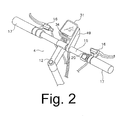
- Fig. 2 is a more detailed view the handlebar assembly
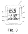
- Fig. 3 is an illustration of items displayed on a computer display
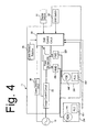
- Fig. 4 is a schematic block diagram of a computer control device for components of the bicycle
- Fig. 5 is a flow chart of a particular embodiment of a routine for controlling the operation of the front and rear deraille;
- Fig. 6 is a side view of another embodiment of a bicycle.
- Fig. 7 is a cross sectional view of the swing arm portion of the bicycle shown in Fig. 6.
- Fig. 1 is a side view of a particular embodiment of a bicycle 1.
- Bicycle 1 is a mountain bicycle that comprises a frame body 1 a and a swing arm 1 b pivotably connected to the rear of frame body 1 a via a rear suspension 13r.
- Frame body 1 a and swing arm 1 b each may be constructed by welding together tubing having noncircular cross-sections.
- a front fork 3 is mounted to the front of frame body 1 a for rotation around an inclined axis, and a handlebar assembly 4 is mounted to the top of front fork 3.
- a saddle 18 is mounted to the upper rear part of frame body 1a, a drive mechanism 5 is mounted to the lower part of frame body 1 a, a front wheel 6 is rotatably mounted to front fork 3 through a front suspension 13f, and a rear wheel 7 having a hub dynamo 10 is rotatably mounted to the rear of swing arm 1 b.
- Hub dynamo 10 houses an alternating current generator 19 (Fig. 4) for generating electricity from the rotation of rear wheel 7.
- a front transmission 8 including an electrically operated front derailleur 26f is mounted to the lower rear part of frame body 1a, and a rear transmission 9 including an electrically operated rear derailleur 26r is mounted to the rear of swing arm 1b.
- handlebar assembly 4 comprises a handle stem 12 mounted to the top of front fork 3 and a handlebar 15 mounted to the top of handle stem 12.
- Brake lever assemblies 16 and grips 17 are mounted at the opposite ends of handlebar 15.
- the right side brake lever assembly 16 includes a switch 20 for manually controlling the operation of front derailleur 26f and rear derailleur 26r in a manner described below.
- a display device 31 in the form of a cycle computer is mounted on handlebar 15 via a bracket 49. As shown in FIG. 3, display device 31 has a segmented liquid crystal display portion 32.
- Liquid crystal display (LCD) portion 32 is provided with a speed display area 32a disposed at an upper portion thereof, a shift mode display area 32b positioned below speed display area 32a, a speed stage display area 32c positioned to the right of shift mode display area 32b, a time display area 32d positioned below shift mode display area 32b, and a distance display area 32e disposed below speed stage display area 32c.
- Shift mode display area 32b indicates shift modes such as a high-speed shift mode (H), a medium-speed shift mode (M), and a low speed shift mode (L). In the high-speed shift mode, shift timings are shifted towards higher speeds compared to the medium-speed shift mode.
- FIG. 3 shows LCD portion indicating the current state of various traveling conditions of the bicycle. For example, a speed of "21.5" kilometers per hour is displayed at the speed display area 32a, the letter “M” indicating medium-speed shift mode is displayed at the shift mode display area 32b, the speed stage “12” is displayed at the speed stage display area 32c, the time “3:36” is displayed in time display area 32d, and "239.8" is displayed in distance display area 32e.
- drive mechanism 5 comprises a crank 27 rotatably mounted at the bottom bracket of frame body 1a, front and rear transmissions 8 and 9, and a chain 29.
- Crank 27 comprises a right crank arm 27a and a left crank arm 27b.
- N eight
- FIG. 1 the number of sprockets R1-R8 is not depicted exactly for simplicity of illustration.
- Front sprockets F1-F3 are arranged in the order of a decreasing number of teeth, wherein front sprocket F1 is the laterally outermost front sprocket having the greatest number of teeth, and front sprocket F3 is the laterally innermost front sprocket having the least number of teeth.
- Rear sprockets R1-R8 also are arranged in the order of a decreasing number of teeth, wherein rear sprocket R1 is the laterally innermost rear sprocket having the most number of teeth, and rear sprocket R8 is the laterally outermost rear sprocket having the least number of teeth.
- chain 29 is positioned to selectively engage one of the front sprockets F1-F3, each corresponding to a shift stage of front derailleur 26f, and chain 29 is positioned to selectively engage one of the rear sprockets R1-R8, each corresponding to a shift stage of rear derailleur 26r.
- a controller 11 (Fig. 4) controls the operation of front derailleur 26f and rear derailleur 26r in response to signals received from shift switch 20 in a manner described below.
- Table 1 An example of the numbers of teeth on front sprockets F1-F3 and rear sprockets R1-R8 is shown in Table 1.
- Table 1 SPROCKET NUMBER OF TEETH F1 46 F2 34 F3 24 R1 33 R2 29 R3 25 R4 21 R5 17 R6 15 R7 13 R8 11
- crank rotation sensor 24 (Fig, 4) is provided for sensing the rotation of crank 27.
- the presence or absence of rotation of crank 27 ordinarily is used in part to control the operation of front and rear transmissions 8 and 9.
- Crank rotation sensor 24 typically comprises a reed switch (not shown) mounted to frame body 1a within the rotation radius of crank 27, and one or more magnets (not shown) mounted to one or both of the crank arms 27a and 27b so that reed switch 23 provides a pulse whenever a magnet passes by. In this embodiment, four such magnets may be used to provide four pulses for each rotation of crank 27.
- Controller 11 controls various components including the front and rear transmissions 8 and 9.
- controller 11 controls front and rear transmissions 8 and 9 in response to the operation of shift switch 20 and bicycle speed.
- Controller 11 may be mounted, for example, on the bottom bracket of frame body 1a in proximity to crank sensor 24 and front derailleur 26f, and it is connected to alternating current generator 19.
- the electrical current generated by alternating current generator 19 powers controller 11, and controller 11 uses the supplied electrical current to control the operation of front derailleur 26f and rear derailleur 26r. Since controller 11 is disposed on the bottom bracket of frame body 1 a, it is fairly close to alternating current generator 19. As a result, a short power cable may be used to connect controller 11 to alternating current generator 19, and the communication of power between the two may be carried out with high efficiency.
- controller 11 includes a shift control circuit 30 that comprises an information processing unit in the form of a microcomputer including a CPU, memory, I/O interface, and the like.
- modules include a traveling state detection circuit in the form of a speed detection circuit 36 for generating pulsed velocity signals from the alternating current signal output from alternating current generator 19, a charge control circuit 33, a power storage unit 38, crank sensor 24, a front motor driver (FMD) 39f for operating a front derailleur motor (FDM) 44f for front derailleur 26f, a rear motor driver (RMD) 39r for operating a rear derailleur motor (RDM) 44r for rear derailleur 26r, a front operating location sensor (FLS) 41 f that provides signals indicating the current operating position of front derailleur 26f; a rear operating location sensor (RLS) 41r that provides signals indicating the current operating position of rear derailleur 26r, shift switch 20, and display device 31.
- FLS front operating location sensor
- Power storage unit 38 may comprise, for example, a large-capacity condenser such as an electric double layer capacitor, and it stores the direct current output from charge control circuit 33.
- power storage unit 38 may comprise a secondary battery such as a nickel-cadmium battery, a lithium ion battery, a nickel hydrogen battery, or some other chare storage device.
- alternating current generator 19 of hub dynamo 10 generates electricity as the bicycle is pedaled, and this electricity is supplied to shift control circuit 30, with power being stored by power storage unit 38. Power from power storage unit 38 is turned on and off by control signals from shift control circuit 30. Shift control circuit 30 also provides control signals to motor drivers 39f and 39r which cause motor drivers 39f and 39r to output motor drive signals for driving motors 44f and 44r provided with deraille 26f and 26r.
- alternating current generator 19 is disposed on rear wheel 7
- power storage unit 38 can be charged simply by turning the pedals, with the bicycle remaining stationary, by lifting the rear wheel.
- Deraille 26f and 26r are controlled according to the operation of switch 20 and the bicycle speed as calculated from speed detection circuit 36. More specifically, when switch 20 is operated, shift control circuit 30 operates front and rear derailleurs 26f and 26r so that drive mechanism 5 is set to the appropriate speed stage according to bicycle speed. Maximum and minimum speed values for each speed stage are stored in a memory associated with shift control circuit 30. As noted previously, there are three shift modes.
- the predetermined bicycle speed values for medium-speed shift mode are shown in Table 4, the predetermined bicycle speed values for low-speed shift mode are shown in Table 5, and the predetermined bicycle speed values for high-speed shift mode are shown in Table 6 Table 4
- Table 5 R1 (km/h) R2 (km/h) R3 (km/h) R4 (km/h) R5 (km/h) R6 (km/h) R7 (km/h) R8 (km/h) F1 18-21 21-25 25-29 29- F2 9-11 11-13.5 13.5-15.5 15.5-18 F3 0-4 4-6 6-7.5 7.5-9
- Table 6 R1 (km/
- the range of bicycle speeds for the third speed stage is 7 kilometers per hour or more and less than 8.5 kilometers per hour. If shift switch 20 is operated when the bicycle speed is 7 kilometers per hour or more and less than 8.5 kilometers per hour, then shift control circuit 30 provides control signals to front and rear motor drivers 39f and 39r to set front and rear deraille 26f and 26r to the positions corresponding to third speed (i.e., front derailleur 26f is positioned to engage chain 29 with front sprocket F3, and rear derailleur 26r is positioned to engage chain 29 with rear sprocket R3.
- front derailleur 26f is positioned to engage chain 29 with front sprocket F3
- rear derailleur 26r is positioned to engage chain 29 with rear sprocket R3.
- Fig. 5 is a flow chart of a particular embodiment of a routine for controlling the operation of drive mechanism 5.
- initialization is performed in a step S1.
- the shift mode may be set to medium-speed mode.
- display processing is performed in a step S2 to transmit various display data to display device 31, and the appropriate data is displayed in a corresponding display area 32a to 32e of LCD portion 32.
- speed data is communicated from shift control circuit 30 to display 31
- speed is displayed in speed display area 32a
- shift mode data is communicated from shift control circuit 30 to display 31
- the appropriate symbol H, M or L indicating the current shift mode is displayed in shift mode display area 32b.
- speed stage data is communicated from shift control circuit 30 to display 31, a value indicating any of the 1 to 12 speed stages is displayed in speed stage display area 32c.
- step S3 It is then determined in a step S3 whether or not shift switch 20 has been operated. If not, then the process proceeds from step S3 to a step S4, wherein it is determined whether or not instructions for other processing (such as derailleur adjustment) have been issued. If not, then the process returns to step S2. However, if instructions for other processing have been issued, then the process jumps to a step S10 to perform the other processing, and thereafter the process returns to step S2.
- instructions for other processing such as derailleur adjustment
- step S3 If it is determined in step S3 that shift switch 20 has been operated, then the process jumps from step S3 to a step S5, wherein it is determined whether or not shift switch 20 has been pressed and held for two seconds or more.
- pressing switch 20 for two seconds or more indicates a desire to change shift modes.
- step S5 if it is determined in step S5 that shift switch 20 has been pressed for two seconds or more, then the shift mode is changed in a step S9.
- the shift mode may be cyclically switched in the sequence of M to L to H each time shift switch 20 is pressed and held, or depending on how long shift switch 20 is pressed and held. Thereafter, the process moves to step S4.
- step S5 If it is determined in step S5 that shift switch 20 has been pressed for less than two seconds, the process moves from step S5 to S6 wherein it is determined from the output of crank sensor 24 whether or not crank 27 is rotating in the traveling direction. If crank 27 is not rotating in the traveling direction, then the process returns to step S4. However, if crank 27 is rotating in the traveling direction, then the process moves from step S6 to S7 wherein a speed St detected by speed detecting circuit 36 at the moment of operation of shift switch 20 is obtained. Thereafter, front and rear deraille 26f and 26r are set to their specific shift stages corresponding to the speed stage Ts corresponding to the shift mode and the speed St. For example, in medium-speed mode, the proper speed stage Ts is determined from speed St and the relationships shown in Table 4.
- front derailleur 26f is set to shift stage F2 and rear derailleur 26r is set to shift stage R5 to correspond to the seventh speed stage.
- the proper speed stage Ts is determined from the current speed St and the values shown in Table 5.
- the proper speed stage Ts is determined from the current speed St and the values shown in Table 5.
- shifting may be achieved by nothing more than a single operation of shift switch 20 whenever shifting is desired without having to operate a plurality of shift levers. Therefore, even novice riders may easily perform shift operations in accordance with their intentions. Furthermore, since the rider can select from a plurality of shift modes, an optimum shift mode that is appropriate for a rider's physical ability may be selected.
- Fig. 6 is a side view of another embodiment of a bicycle
- Fig. 7 is a cross sectional view of the swing arm portion of the bicycle shown in Fig. 6.
- a bicycle 101 comprises a frame body 101 a, a swing arm 101 b pivotably connected to frame body 101 a through a rear suspension 113r, a front fork 103, a handlebar assembly 104, a drive mechanism 105 including an internal transmission 109, a front wheel 106 rotatably mounted to front fork 103, a rear wheel 107 rotatably mounted with internal transmission 109, an alternating current generator 119 disposed within internal transmission 109, and a shift control circuit 111 for controlling the operation of internal transmission 109.
- Speed threshold values corresponding to the eight speed stages are stored within a memory associated with shift control circuit 111.
- Electric cable drive device 127 includes a motor and a cable positioning mechanism (not shown). Electric cable drive device 127 causes internal hub transmission 126 to perform shift operations to selected ones of the eight speed stages through a shift cable 128.
- shift control circuit 111 and electric cable drive device 127 are mounted on swing arm 101 b.
- a shift switch similar to that shown for the previous embodiment is provided on handlebar assembly 104.
- shift control circuit 111 sets internal hub transmission 126 to a specific speed stage corresponding to the bicycle speed.
- bicycle speed may be detected as in the first embodiment by performing waveform-shaping on the alternating current signal output from alternating current generator 119.
- bicycle speed was detected using outputs from an alternating current generator
- many other ways of detecting bicycle speed are known.
- bicycle speed may be detected using a reed switch disposed on a first member of the bicycle (e.g., front fork 3), and a magnet or the like disposed on a second member of the bicycle (e.g., front wheel 6) that moves relative to the first member.
- a push-button switch was used as shift switch 20, a lever-type switch, a rocker switch or a number of other switches may be used instead.
- shift control circuit 30 and other elements were mounted on the bottom bracket portion of frame body 1 b, the various components and/or functions may be distributed as desired, such as mounting one or more components on front derailleur 26f and/or rear derailleur 26r to simplify wiring operations.
Landscapes
- Engineering & Computer Science (AREA)
- Chemical & Material Sciences (AREA)
- Combustion & Propulsion (AREA)
- Transportation (AREA)
- Mechanical Engineering (AREA)
- Control Of Transmission Device (AREA)
- Electric Propulsion And Braking For Vehicles (AREA)
Applications Claiming Priority (1)
| Application Number | Priority Date | Filing Date | Title |
|---|---|---|---|
| JP2006172780A JP2008001229A (ja) | 2006-06-22 | 2006-06-22 | 自転車用変速制御装置及び自転車用変速制御方法 |
Publications (3)
| Publication Number | Publication Date |
|---|---|
| EP1870329A2 true EP1870329A2 (de) | 2007-12-26 |
| EP1870329A3 EP1870329A3 (de) | 2010-01-13 |
| EP1870329B1 EP1870329B1 (de) | 2012-05-16 |
Family
ID=38515355
Family Applications (1)
| Application Number | Title | Priority Date | Filing Date |
|---|---|---|---|
| EP06024570A Active EP1870329B1 (de) | 2006-06-22 | 2006-11-28 | Steuerungseinrichtung für eine Fahrradgangschaltung, die auf einen manuell betätigten Schalter anspricht |
Country Status (4)
| Country | Link |
|---|---|
| US (1) | US8235408B2 (de) |
| EP (1) | EP1870329B1 (de) |
| JP (1) | JP2008001229A (de) |
| CN (1) | CN101092158B (de) |
Families Citing this family (21)
| Publication number | Priority date | Publication date | Assignee | Title |
|---|---|---|---|---|
| CA2726248A1 (en) * | 2008-05-30 | 2009-12-03 | Bombardier Recreational Products Inc. | Vehicle with a display device operated from a handlebar |
| US7900946B2 (en) * | 2009-03-31 | 2011-03-08 | Shimano Inc. | Bicycle shifting control apparatus |
| CN103402840B (zh) | 2011-02-21 | 2015-12-02 | 铃木株式会社 | 混合动力车辆的驱动控制装置 |
| US8721495B2 (en) * | 2011-06-17 | 2014-05-13 | Shimano Inc. | Rear derailleur and gear shift system |
| JP2013047657A (ja) * | 2011-08-29 | 2013-03-07 | Shimano Inc | 自転車用センサの制御装置、自転車用センサの制御方法 |
| US8886417B2 (en) | 2011-09-09 | 2014-11-11 | Sram, Llc | Bicycles with electronic shifting systems and methods |
| TWI452801B (zh) * | 2011-12-27 | 2014-09-11 | Univ Nat Chiao Tung | 根據路況調整充電狀態之充電裝置及其方法 |
| JP2013177085A (ja) * | 2012-02-29 | 2013-09-09 | Bridgestone Cycle Co | ダブルスタンド自転車 |
| CN102874371B (zh) * | 2012-10-09 | 2017-07-14 | 天津市松正电动汽车技术股份有限公司 | 一种电动车调速系统及其方法 |
| JP5753865B2 (ja) * | 2013-02-28 | 2015-07-22 | 東芝テック株式会社 | アシストロボットおよびその制御プログラム |
| US20150285376A1 (en) * | 2014-04-03 | 2015-10-08 | Colleen M. Hageman | Bicycle gear shift indicator and display |
| JP5778830B1 (ja) * | 2014-05-29 | 2015-09-16 | 株式会社シマノ | 自転車用の変速制御装置、電動アシストシステム、および、自転車用の変速制御方法 |
| DE102015000422A1 (de) * | 2015-01-14 | 2016-07-14 | Sram Deutschland Gmbh | Verfahren und Vorrichtung zum Steuern automatischer Schaltvorgänge einer elektrischen Gangschaltvorrichtung eines Fahrrads |
| US9669901B2 (en) | 2015-03-05 | 2017-06-06 | Shimano Inc. | Bicycle electric shifting apparatus |
| JP6567928B2 (ja) * | 2015-03-06 | 2019-08-28 | 株式会社シマノ | 自転車の電動システム |
| JP3200367U (ja) * | 2015-07-29 | 2015-10-15 | 株式会社シマノ | 自転車用制御装置およびこれを備える自転車用制御システム |
| US9944350B2 (en) | 2016-01-11 | 2018-04-17 | Sram, Llc | Chain guide sensor and methods of controling a bicycle |
| CN107867369A (zh) * | 2016-09-23 | 2018-04-03 | 许健平 | 自行车自动换档方法及系统 |
| US10829179B2 (en) | 2019-04-05 | 2020-11-10 | Shimano Inc. | Control system for human-powered vehicle |
| JP7309476B2 (ja) * | 2019-06-25 | 2023-07-18 | 株式会社シマノ | 人力駆動車用の制御装置および人力駆動車用の変速システム |
| CN113492945B (zh) * | 2021-07-23 | 2023-05-26 | 深圳大学 | 变速执行机构、自行车变速器及控制方法 |
Citations (1)
| Publication number | Priority date | Publication date | Assignee | Title |
|---|---|---|---|---|
| JPH05319355A (ja) | 1992-05-14 | 1993-12-03 | Shimano Inc | 自転車用変速操作装置 |
Family Cites Families (16)
| Publication number | Priority date | Publication date | Assignee | Title |
|---|---|---|---|---|
| US4490127A (en) * | 1981-05-29 | 1984-12-25 | Sanyo Electric Co., Ltd. | Electrically operated transmission gear system for bicycles |
| US5213548A (en) | 1992-03-02 | 1993-05-25 | Colbert Ralph G | Gear shifting system for derailleur equipped bicycle |
| JPH08113183A (ja) * | 1994-10-14 | 1996-05-07 | Akebono Brake Ind Co Ltd | 自動変速装置付自転車 |
| US5553510A (en) * | 1995-02-27 | 1996-09-10 | Balhorn; Alan C. | Multi-speed transmission |
| US5599244A (en) * | 1995-08-14 | 1997-02-04 | Ethington; Russell A. | Automatic transmission shifter for velocipedes |
| JP3284060B2 (ja) * | 1996-09-20 | 2002-05-20 | 株式会社シマノ | 自転車の変速制御方法及びその変速制御装置 |
| US20030100392A1 (en) * | 2001-11-23 | 2003-05-29 | Tadashi Ichida | Method and apparatus for shifting a bicycle transmission |
| JP3654868B2 (ja) * | 2002-02-21 | 2005-06-02 | 株式会社シマノ | 自転車用変速制御装置及び自転車用変速制御方法 |
| JP3703810B2 (ja) * | 2003-02-25 | 2005-10-05 | 株式会社シマノ | 自転車用自動変速制御装置 |
| JP3770394B2 (ja) * | 2003-02-25 | 2006-04-26 | 株式会社シマノ | 自転車用変速制御装置 |
| JP3703809B2 (ja) * | 2003-02-25 | 2005-10-05 | 株式会社シマノ | 自転車用自動変速制御装置 |
| JP2004256047A (ja) * | 2003-02-27 | 2004-09-16 | Shimano Inc | 自転車用距離表示システム及び距離表示装置 |
| JP3717076B2 (ja) * | 2003-03-11 | 2005-11-16 | 株式会社シマノ | 二輪車用変速制御装置 |
| JP3777360B2 (ja) * | 2003-03-27 | 2006-05-24 | 株式会社シマノ | 自転車用情報処理装置 |
| JP4078331B2 (ja) | 2004-05-13 | 2008-04-23 | 株式会社シマノ | 自転車用駆動ユニット |
| JP2006001438A (ja) * | 2004-06-18 | 2006-01-05 | Shimano Inc | 自転車用制御装置及び自転車用シートピラー |
-
2006
- 2006-06-22 JP JP2006172780A patent/JP2008001229A/ja not_active Ceased
- 2006-10-25 US US11/552,759 patent/US8235408B2/en not_active Expired - Fee Related
- 2006-11-28 EP EP06024570A patent/EP1870329B1/de active Active
- 2006-11-30 CN CN2006101636842A patent/CN101092158B/zh not_active Expired - Fee Related
Patent Citations (1)
| Publication number | Priority date | Publication date | Assignee | Title |
|---|---|---|---|---|
| JPH05319355A (ja) | 1992-05-14 | 1993-12-03 | Shimano Inc | 自転車用変速操作装置 |
Also Published As
| Publication number | Publication date |
|---|---|
| EP1870329A3 (de) | 2010-01-13 |
| JP2008001229A (ja) | 2008-01-10 |
| EP1870329B1 (de) | 2012-05-16 |
| US8235408B2 (en) | 2012-08-07 |
| CN101092158B (zh) | 2010-07-28 |
| US20070296176A1 (en) | 2007-12-27 |
| CN101092158A (zh) | 2007-12-26 |
Similar Documents
| Publication | Publication Date | Title |
|---|---|---|
| EP1870329B1 (de) | Steuerungseinrichtung für eine Fahrradgangschaltung, die auf einen manuell betätigten Schalter anspricht | |
| USRE43562E1 (en) | Bicycle shift control apparatus that prevents undesirable chain angles | |
| US7288038B2 (en) | Bicycle shift control apparatus with preferential shifting | |
| US6959941B2 (en) | Bicycle shift control apparatus that selectively restricts speed stages | |
| US6959939B2 (en) | Electronic bicycle shift control device | |
| US9151379B2 (en) | Bicycle gear changing apparatus | |
| US7730803B2 (en) | Switch designation apparatus for a bicycle control unit | |
| US7379798B2 (en) | Bicycle display apparatus with distributed processing | |
| US8882122B2 (en) | Bicycle gear changing apparatus | |
| US7311322B2 (en) | Bicycle control apparatus that sets a bicycle transmission to a predetermined gear ratio | |
| EP1391375A1 (de) | Vorrichtung zur Leistungsstabilisierung für elektrische Fahrradkomponenten |
Legal Events
| Date | Code | Title | Description |
|---|---|---|---|
| PUAI | Public reference made under article 153(3) epc to a published international application that has entered the european phase |
Free format text: ORIGINAL CODE: 0009012 |
|
| AK | Designated contracting states |
Kind code of ref document: A2 Designated state(s): AT BE BG CH CY CZ DE DK EE ES FI FR GB GR HU IE IS IT LI LT LU LV MC NL PL PT RO SE SI SK TR |
|
| AX | Request for extension of the european patent |
Extension state: AL BA HR MK YU |
|
| PUAL | Search report despatched |
Free format text: ORIGINAL CODE: 0009013 |
|
| AK | Designated contracting states |
Kind code of ref document: A3 Designated state(s): AT BE BG CH CY CZ DE DK EE ES FI FR GB GR HU IE IS IT LI LT LU LV MC NL PL PT RO SE SI SK TR |
|
| AX | Request for extension of the european patent |
Extension state: AL BA HR MK RS |
|
| 17P | Request for examination filed |
Effective date: 20100217 |
|
| 17Q | First examination report despatched |
Effective date: 20100318 |
|
| AKX | Designation fees paid |
Designated state(s): DE IT NL |
|
| GRAP | Despatch of communication of intention to grant a patent |
Free format text: ORIGINAL CODE: EPIDOSNIGR1 |
|
| GRAS | Grant fee paid |
Free format text: ORIGINAL CODE: EPIDOSNIGR3 |
|
| GRAA | (expected) grant |
Free format text: ORIGINAL CODE: 0009210 |
|
| AK | Designated contracting states |
Kind code of ref document: B1 Designated state(s): DE IT NL |
|
| REG | Reference to a national code |
Ref country code: NL Ref legal event code: T3 |
|
| REG | Reference to a national code |
Ref country code: DE Ref legal event code: R096 Ref document number: 602006029391 Country of ref document: DE Effective date: 20120719 |
|
| PLBE | No opposition filed within time limit |
Free format text: ORIGINAL CODE: 0009261 |
|
| STAA | Information on the status of an ep patent application or granted ep patent |
Free format text: STATUS: NO OPPOSITION FILED WITHIN TIME LIMIT |
|
| 26N | No opposition filed |
Effective date: 20130219 |
|
| REG | Reference to a national code |
Ref country code: DE Ref legal event code: R097 Ref document number: 602006029391 Country of ref document: DE Effective date: 20130219 |
|
| PGFP | Annual fee paid to national office [announced via postgrant information from national office to epo] |
Ref country code: NL Payment date: 20161010 Year of fee payment: 11 |
|
| PGFP | Annual fee paid to national office [announced via postgrant information from national office to epo] |
Ref country code: IT Payment date: 20161122 Year of fee payment: 11 |
|
| REG | Reference to a national code |
Ref country code: NL Ref legal event code: MM Effective date: 20171201 |
|
| PG25 | Lapsed in a contracting state [announced via postgrant information from national office to epo] |
Ref country code: NL Free format text: LAPSE BECAUSE OF NON-PAYMENT OF DUE FEES Effective date: 20171201 Ref country code: IT Free format text: LAPSE BECAUSE OF NON-PAYMENT OF DUE FEES Effective date: 20171128 |
|
| P01 | Opt-out of the competence of the unified patent court (upc) registered |
Effective date: 20230428 |
|
| REG | Reference to a national code |
Ref country code: DE Ref legal event code: R082 Ref document number: 602006029391 Country of ref document: DE Representative=s name: HOFFMANN EITLE PATENT- UND RECHTSANWAELTE PART, DE |
|
| PGFP | Annual fee paid to national office [announced via postgrant information from national office to epo] |
Ref country code: DE Payment date: 20250930 Year of fee payment: 20 |