EP1870515B1 - Assise de machine - Google Patents
Assise de machine Download PDFInfo
- Publication number
- EP1870515B1 EP1870515B1 EP07104203A EP07104203A EP1870515B1 EP 1870515 B1 EP1870515 B1 EP 1870515B1 EP 07104203 A EP07104203 A EP 07104203A EP 07104203 A EP07104203 A EP 07104203A EP 1870515 B1 EP1870515 B1 EP 1870515B1
- Authority
- EP
- European Patent Office
- Prior art keywords
- transfer belt
- machine
- press
- supporting
- support
- Prior art date
- Legal status (The legal status is an assumption and is not a legal conclusion. Google has not performed a legal analysis and makes no representation as to the accuracy of the status listed.)
- Not-in-force
Links
- 238000000034 method Methods 0.000 claims abstract description 8
- 238000003825 pressing Methods 0.000 abstract description 7
- 238000010276 construction Methods 0.000 description 5
- 238000001035 drying Methods 0.000 description 5
- 125000006850 spacer group Chemical group 0.000 description 4
- 230000003750 conditioning effect Effects 0.000 description 3
- 238000003780 insertion Methods 0.000 description 3
- 230000037431 insertion Effects 0.000 description 3
- 238000004804 winding Methods 0.000 description 2
- 230000015572 biosynthetic process Effects 0.000 description 1
- 238000004140 cleaning Methods 0.000 description 1
- 238000002360 preparation method Methods 0.000 description 1
- 238000003860 storage Methods 0.000 description 1
- 238000011144 upstream manufacturing Methods 0.000 description 1
Images


Classifications
-
- D—TEXTILES; PAPER
- D21—PAPER-MAKING; PRODUCTION OF CELLULOSE
- D21F—PAPER-MAKING MACHINES; METHODS OF PRODUCING PAPER THEREON
- D21F7/00—Other details of machines for making continuous webs of paper
- D21F7/001—Wire-changing arrangements
-
- D—TEXTILES; PAPER
- D21—PAPER-MAKING; PRODUCTION OF CELLULOSE
- D21F—PAPER-MAKING MACHINES; METHODS OF PRODUCING PAPER THEREON
- D21F3/00—Press section of machines for making continuous webs of paper
- D21F3/02—Wet presses
- D21F3/04—Arrangements thereof
Definitions
- the invention relates to a press section for dewatering a paper, board, tissue or another fibrous web in a machine for producing and / or finishing the same, wherein the press section comprises a plurality of separate press nips formed by press rolls, the ends of the press rolls in each case drive and leader-side support structure of a machine chair are mounted and at least one water-absorbing and endlessly circulating dewatering belt is guided through this press nip next to the fibrous web, a dewatering belt and an endless transfer belt running through a press nip.
- the invention also relates to a method for changing an endless transfer belt of a machine with a machine chair.
- the press section has a drive and a driver-side support structure.
- a plurality of pressing and guide rollers are mounted, which are arranged in various configurations relative to each other.
- An essential part of the press section is formed by water-absorbing drainage tapes including their guidance and conditioning. Since these drainage tapes must be replaced frequently, sufficient accessibility must be ensured.
- the object of the invention is therefore to provide a stable and structurally simple press section with a machine chair, which allows the best possible accessibility and a gentle change of the transfer belt.
- the transverse seams can be opened and the band parts are led out of the machine individually.
- the assembly is easy by the band parts individually fed into the machine and the transverse seams are closed.
- Removable intermediate pieces are only available for the change of the transfer belt in the area of the corresponding press roll.
- the feeding of the transfer belt in the machine extends between the support structures near and parallel to, embraced by the transfer belt press roller an inner track for a carriage.
- the advantages can be optimized in terms of a material and weight-saving support structure, if in at least one, preferably a plurality of support structures, the support beams are connected in a, each lying in the machine direction plane together so that arise between these triangular spaces.
- the triangular free spaces should be predominantly, preferably exclusively, above the machine foundation.
- the triangular free spaces should be at least 1 m, preferably at least 1.5 m above the machine foundation.
- the support beams forming a corner of a triangular free space that form the foundation of the machine are connected to one end of a support beam extending vertically and preferably supported on the machine foundation.
- the supporting structures should extend over at least part of the press section with a plurality of press nips, preferably over the entire press section.
- Each support structure with these triangular free spaces is formed so completely or largely in one piece in the longitudinal direction of the machine.
- integrally means that these may well consist of two or more subassemblies, provided that these subassemblies are joined together so stably that a rigidity arises, as with a single component.
- the stability of the machine chair can be increased by connecting the supporting structures to one another via crossbeams.
- the guide carrier running axially to the press belt and preferably extending over the width of the transfer belt, has a removable intermediate piece with the support structure of this side the machine frame or the machine foundation coupled support part of the press roll is connected, the guide carrier has an axially extending to the press roller, outer track, which continues in the machine via inner track, wherein on the outer track rail a carriage for Receiving and guiding the transfer belt is located, which drives the transfer belt after the removal of the intermediate pieces in the machine.
- the transfer belt can be prepared unrequited in its entire width outside the machine on the tape change.
- the retraction of the transfer belt by means of the carriage in the region of the inner track designed much easier.
- the press roller can be held on the guide support, so that no Cantilever- or cross member is required for the Supporteile this press roll. This not only reduces the effort, but also the burden on the building structure.
- the outer end of the guide carrier should be attached to a crane.
- the transfer belt should be brought after fixing on the carriage over axially extending to the press roller draping into a shape corresponding approximately to the course in the machine.
- the drapery tubes can be fastened with advantage on the guide support.
- the release of the intermediate pieces can be done relatively easily via the lifting of the guide support after loosening corresponding connections in the machine frame.
- the guide carrier can be lifted with advantage over the crane or via a lifting element supported on the foundation.
- the guide carrier should preferably be connected to the guide part of the machine with the support part.
- press section comprises two press nips, which are formed by two compressed press rolls 4.
- the separate press roller pairs are supported at the ends of support parts in the form of a foundation 5, which is supported on the machine foundation 16.
- the fibrous web 1 runs on both sides with a respective dewatering belt 11, 12.
- the fibrous web 1 is guided by an upper dewatering belt 14 and a lower, smooth and impermeable transfer belt 13 through the second press nip.
- the drainage tapes 11,12,14 are carried out as water-absorbing press felts.
- the upper dewatering belt 12 of the first press nip takes over the fibrous web 1 from a forming wire 10 of an upstream former for sheet formation.
- the fibrous web 1 runs together with both dewatering belts 11, 12 before the upper dewatering belt 12 is led away. From the sole leading lower dewatering belt 11, the fibrous web 1 is then transferred to the upper dewatering belt 14 of the second press nip.
- the lower transfer belt 13 guides the fibrous web 1 until it is taken over by a drying wire 15 of a following drying section for drying the fibrous web 1.
- the fibrous web 1 is supported by the drying wire 15, alternately guided over heated drying cylinders 9 and suctioned guide rollers 18. Die Trocknungszylinder 9 Sind in denget Items 9 anry.
- the dewatering belts 11, 12, 14 and the transfer belt 13 are guided past the press nips via guide rollers 7, 8 and to conditioning devices for cleaning and dewatering the belts.
- the upper dewatering belts 12, 14 run horizontally in the region of the corresponding conditioning devices and approximately at the same height above the machine foundation 16.
- the machine chair On the drive and guide side, the machine chair is each formed by supporting structure, which is composed of stringers 2 and foundations 5.
- the supporting beams 2 are in a plane lying in the machine running direction 6 with each other connected that arise between these triangular spaces 3. These and other free spaces greatly enhance the accessibility of the machine.
- cross member 22 To stabilize the supporting structures via cross member 22 are interconnected.
- the free spaces 3 have here the shape of an acute-angled triangle.
- the machine foundation 16 facing corner of the triangular space 3 forming support beams 2 connected to one end of a vertically extending and preferably supported on the machine foundation 16 support beam 2. In this way, at this corner of the triangle results in a y-shaped connection of the support beams. 2
- Removable intermediate pieces are only available for the change of the transfer belt in the area of the corresponding press roll. This makes a very stable construction of the machine chair possible.
- the acting as tension rollers guide rollers 8 of the upper dewatering belts 12,14 are mounted on the upper support beam.
- the Clamping direction of acting as tension rollers guide rollers 8 of the adjacent, upper dewatering belts 12,14 opposite to increase the compactness.
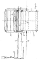
- FIGS. 2 to 5 For simplicity of illustration of the band changing method, only one press roller pair is shown, the press rollers 4 being mounted on both sides in the machine frame, which is supported on the machine foundation 16.
- the fibrous web 1 is guided together with an upper water-absorbing dewatering belt 14 and a lower, smooth, impermeable belt 13.
- the machine chair On the driver's side, the machine chair comprises separate support parts 20, 21 for supporting the press rollers 4. These support parts 20, 21 are spaced apart and supported separately.
- the support parts 20,21 the leader are connected via axially extending to the press roll 4 cross member 22 with the opposite machine frame.
- the belts 13, 14 are guided over guide rollers 7.
- the endless circulating transfer belt 13 is not only seamless, but also smooth and therefore not gatherable, this is performed here with a special changing device in the machine.
- the old transfer belt 13 to be changed can be easily separated and removed from the machine.
- This carriage 25 carries the new transfer belt 13, which is fixed on a winding tube on the unwinding of the carriage 25.
- the transfer belt 13 can be brought about axially extending to the press roller 4 Drapierrohre in an approximately the course in the machine corresponding shape.
- the drapery tubes can be easily attached to the guide bracket 23.
- the transfer belt 13 Since the guide carrier 23 extends over the entire width of the transfer belt 13, the transfer belt 13 does not have to be gathered, which in particular protects the smooth surface of the transfer belt 13.
- the carriage 25 consists here of a part of each carriage at each end of the transfer belt 13th
- the free end of the guide carrier 23 can subsequently be raised, which allows the removal of the intermediate pieces 28.
- the carriage 25 After mounting the transfer belt 13 in the machine, the carriage 25 can be driven out of the machine and removed together with the guide support 23.
- the support structure formed by the support beam 2 can be constructed very stable and simple.
Landscapes
- Paper (AREA)
- Treatment Of Fiber Materials (AREA)
- Structure Of Belt Conveyors (AREA)
Claims (10)
- Section de presse pour égoutter une nappe de papier, carton, papier-tissu ou une autre nappe fibreuse (1) d'une machine de fabrication et/ou d'amélioration de celle-ci, dans laquelle la section de presse comprend plusieurs pinçages de presse séparés formés par des rouleaux de presse (4), les extrémités des rouleaux de presse (4) sont montées à chaque fois dans une construction porteuse d'une assise de machine du côté de l'entraînement et du côté de l'opérateur, et au moins une bande d'égouttage (11, 12, 14) absorbant l'eau et entraînée sans fin est guidée à travers ce pinçage de presse en plus de la nappe fibreuse (1), une bande d'égouttage (14) et une bande de transfert sans fin (13) passant à travers un pinçage de presse, caractérisée en ce que
toutes les bandes d'égouttage (11, 12, 14) possèdent des joints transversaux pouvant être ouverts et fermés, la construction porteuse comprend des pièces intermédiaires (28) à enlever uniquement pour l'insertion de la bande de transfert (13), un rail de roulement intérieur (26) pour un chariot de roulement (25) s'étend entre les constructions porteuses à proximité du rouleau de presse (4) entouré par la bande de transfert (13) et parallèlement à celui-ci, et pour le remplacement d'une bande de transfert sans fin (13), présente un support de guidage (23) s'étendant axialement par rapport au rouleau de presse (4) entouré par la bande de transfert (13),
lequel support de guidage possède un rail de roulement extérieur (27) s'étendant axialement par rapport au rouleau de presse (4), qui se prolonge dans la machine au-delà du rail de roulement intérieur (26), un chariot de roulement (25) pour recevoir et guider la bande de transfert (13) se trouvant sur le rail de roulement extérieur (27). - Section de presse selon la revendication 1,
caractérisée en ce que
les constructions porteuses sont formées par des poutres porteuses (2, 19) et des bases (5), le rouleau de presse (4) entouré par la bande de transfert (13) étant supporté par une base (5) et les poutres porteuses (2) étant connectées les unes aux autres sans pièce intermédiaire amovible (28). - Section de presse selon la revendication 1 ou 2, caractérisée en ce que dans le cas d'au moins une, et de préférence de plusieurs, constructions porteuses, les poutres porteuses (2) sont connectées les unes aux autres dans un plan situé à chaque fois dans la direction d'avance de la machine (6), de telle sorte que des espaces libres triangulaires (3) soient formés entre celles-ci.
- Section de presse selon la revendication 3, caractérisée en ce que les poutres porteuses (2) formant un coin d'un espace libre triangulaire (3) tourné vers la base de la machine (16) sont connectées à une extrémité d'une poutre porteuse (2) s'étendant verticalement et s'appuyant de préférence sur la base de la machine (16).
- Section de presse selon l'une quelconque des revendications précédentes, caractérisée en ce que les constructions porteuses s'étendent au moins sur une partie de la section de presse avec plusieurs pinçages de presse, de préférence sur toute la section de presse.
- Section de presse selon l'une quelconque des revendications précédentes, caractérisée en ce que les constructions porteuses sont connectées les unes aux autres par le biais de supports transversaux (22).
- Section de presse selon l'une quelconque des revendications précédentes, caractérisée en ce que la bande de transfert (13) s'étend sous la nappe fibreuse (1) .
- Procédé pour remplacer une bande de transfert sans fin d'une machine comprenant une section de presse selon l'une quelconque des revendications précédentes, caractérisé en ce que sur un côté de l'assise de la machine, de préférence le côté opérateur, une extrémité d'un support de guidage (23) s'étendant axialement par rapport au rouleau de presse (4) entouré par la bande de transfert (13) et s'étendant de préférence sur la largeur de la bande de transfert (13), est connectée à une partie de support (20, 21) du rouleau de presse (4) accouplée par le biais de pièces intermédiaires amovibles (28) à la construction porteuse de ce côté de l'assise de la machine ou de la base de la machine (16), le support de guidage (23) possède un rail de roulement extérieur (27) s'étendant axialement par rapport au rouleau de presse (4), lequel rail de roulement se prolonge dans la machine au-delà du rail de roulement intérieur (26), un chariot de roulement (25) pour recevoir et guider la bande de transfert (13) se trouvant sur le rail de roulement extérieur (27), lequel amène la bande de transfert (13) après l'enlèvement des pièces intermédiaires (28) dans la machine.
- Procédé selon la revendication 8, caractérisé en ce que
la bande de transfert (13) est amenée après la fixation sur le chariot de roulement (25) par le biais de tubes de drapage s'étendant axialement par rapport au rouleau de presse (4) à une forme correspondant approximativement à la progression dans la machine. - Procédé selon la revendication 8 ou 9, caractérisé en ce que le support de guidage (23) est soulevé pour détacher les pièces intermédiaires (28).
Applications Claiming Priority (1)
| Application Number | Priority Date | Filing Date | Title |
|---|---|---|---|
| DE102006028419A DE102006028419A1 (de) | 2006-06-21 | 2006-06-21 | Maschinenstuhlung |
Publications (2)
| Publication Number | Publication Date |
|---|---|
| EP1870515A1 EP1870515A1 (fr) | 2007-12-26 |
| EP1870515B1 true EP1870515B1 (fr) | 2011-08-03 |
Family
ID=38008032
Family Applications (1)
| Application Number | Title | Priority Date | Filing Date |
|---|---|---|---|
| EP07104203A Not-in-force EP1870515B1 (fr) | 2006-06-21 | 2007-03-15 | Assise de machine |
Country Status (3)
| Country | Link |
|---|---|
| EP (1) | EP1870515B1 (fr) |
| AT (1) | ATE518990T1 (fr) |
| DE (1) | DE102006028419A1 (fr) |
Families Citing this family (2)
| Publication number | Priority date | Publication date | Assignee | Title |
|---|---|---|---|---|
| FI121966B (fi) * | 2009-11-02 | 2011-06-30 | Metso Paper Inc | Saumallisen kudoksen vaihtolaitteisto ja -menetelmä kuiturainakonetta varten |
| DE102018106122A1 (de) * | 2018-03-16 | 2019-09-19 | Voith Patent Gmbh | Pressenpartie |
Family Cites Families (2)
| Publication number | Priority date | Publication date | Assignee | Title |
|---|---|---|---|---|
| FI991171A0 (fi) * | 1999-05-24 | 1999-05-24 | Valmet Corp | Menetelmä siirtohihnan vaihtamiseksi paperi- tai kartonkikoneessa |
| DE102004046060A1 (de) * | 2004-09-21 | 2006-03-23 | Voith Paper Patent Gmbh | Maschine zum Erzeugen einer Bahn aus Papier oder Karton oder einem anderen flächigen Material |
-
2006
- 2006-06-21 DE DE102006028419A patent/DE102006028419A1/de not_active Withdrawn
-
2007
- 2007-03-15 EP EP07104203A patent/EP1870515B1/fr not_active Not-in-force
- 2007-03-15 AT AT07104203T patent/ATE518990T1/de active
Also Published As
| Publication number | Publication date |
|---|---|
| DE102006028419A1 (de) | 2007-12-27 |
| EP1870515A1 (fr) | 2007-12-26 |
| ATE518990T1 (de) | 2011-08-15 |
Similar Documents
| Publication | Publication Date | Title |
|---|---|---|
| EP1870515B1 (fr) | Assise de machine | |
| EP1806307B1 (fr) | Dispositif de changement | |
| DE3916740C2 (de) | Textilmaschine mit verstellbarer Glättwalzenanordnung | |
| DE1147470B (de) | Vorrichtung zum Herstellen von Bahnen aus Papier, Pappe od. dgl. | |
| DE3205360A1 (de) | Verfahren und vorrichtung zum auswechseln eines pick-up-tuches und/oder eines presstuches der pressenpartie einer papiermaschine | |
| DE3330423C2 (fr) | ||
| AT410326B (de) | Verfahren und vorrichtung zum wechseln eines rundfilzes | |
| EP3030712B1 (fr) | Dispositif tendeur destiné à tendre une toile de formage d'une machine à papier | |
| EP3686341B1 (fr) | Changement de cylindre | |
| EP0799931B1 (fr) | Presse à rouleaux | |
| EP3540120B1 (fr) | Partie de presse | |
| DE102006000324A1 (de) | Anordnung und Verfahren zum Wechseln eines endlosen Bandes oder dergleichen in einer Papier- oder Kartonmaschine oder Nachbehandlungsmaschine | |
| DE3335177C2 (fr) | ||
| EP0877115B1 (fr) | Dispositif d'aspiration | |
| EP1637648B1 (fr) | Section de presse d'une machine de fabrication d'une bande de papier ou de carton | |
| DE1295349B (de) | Papiermaschine | |
| DE2307848A1 (de) | Mehrlagen-kartonmaschine | |
| DE102004046062A1 (de) | Verfahren und Vorrichtung zum Austauschen eines alten Bandes gegen ein neues Band in einer Maschine, insbesondere zum Wechsel eines Filzes in einer Papiermaschine | |
| DE3231511C2 (de) | Vorrichtung zum seitlichen Einfahren eines endlosen Bandes in eine Papiermaschine | |
| DE102006028417A1 (de) | Maschinenstuhlung | |
| DE102006028418A1 (de) | Maschinenstuhlung | |
| DE3100522A1 (de) | Walzenpresse | |
| DE102004046060A1 (de) | Maschine zum Erzeugen einer Bahn aus Papier oder Karton oder einem anderen flächigen Material | |
| DE1808403C (de) | Papiermaschine zur Herstellung mehrlagiger Faserbahnen | |
| DE102012205186A1 (de) | Presswalze für eine Maschine zur Herstellung einer Faserstoffbahn |
Legal Events
| Date | Code | Title | Description |
|---|---|---|---|
| PUAI | Public reference made under article 153(3) epc to a published international application that has entered the european phase |
Free format text: ORIGINAL CODE: 0009012 |
|
| AK | Designated contracting states |
Kind code of ref document: A1 Designated state(s): AT BE BG CH CY CZ DE DK EE ES FI FR GB GR HU IE IS IT LI LT LU LV MC MT NL PL PT RO SE SI SK TR |
|
| AX | Request for extension of the european patent |
Extension state: AL BA HR MK YU |
|
| 17P | Request for examination filed |
Effective date: 20080626 |
|
| AKX | Designation fees paid |
Designated state(s): AT BE BG CH CY CZ DE DK EE ES FI FR GB GR HU IE IS IT LI LT LU LV MC MT NL PL PT RO SE SI SK TR |
|
| 17Q | First examination report despatched |
Effective date: 20100506 |
|
| GRAP | Despatch of communication of intention to grant a patent |
Free format text: ORIGINAL CODE: EPIDOSNIGR1 |
|
| GRAS | Grant fee paid |
Free format text: ORIGINAL CODE: EPIDOSNIGR3 |
|
| GRAA | (expected) grant |
Free format text: ORIGINAL CODE: 0009210 |
|
| AK | Designated contracting states |
Kind code of ref document: B1 Designated state(s): AT BE BG CH CY CZ DE DK EE ES FI FR GB GR HU IE IS IT LI LT LU LV MC MT NL PL PT RO SE SI SK TR |
|
| REG | Reference to a national code |
Ref country code: GB Ref legal event code: FG4D Free format text: NOT ENGLISH |
|
| REG | Reference to a national code |
Ref country code: CH Ref legal event code: EP |
|
| REG | Reference to a national code |
Ref country code: IE Ref legal event code: FG4D Free format text: LANGUAGE OF EP DOCUMENT: GERMAN |
|
| REG | Reference to a national code |
Ref country code: DE Ref legal event code: R096 Ref document number: 502007007848 Country of ref document: DE Effective date: 20110929 |
|
| REG | Reference to a national code |
Ref country code: NL Ref legal event code: VDEP Effective date: 20110803 |
|
| LTIE | Lt: invalidation of european patent or patent extension |
Effective date: 20110803 |
|
| PG25 | Lapsed in a contracting state [announced via postgrant information from national office to epo] |
Ref country code: SE Free format text: LAPSE BECAUSE OF FAILURE TO SUBMIT A TRANSLATION OF THE DESCRIPTION OR TO PAY THE FEE WITHIN THE PRESCRIBED TIME-LIMIT Effective date: 20110803 Ref country code: IS Free format text: LAPSE BECAUSE OF FAILURE TO SUBMIT A TRANSLATION OF THE DESCRIPTION OR TO PAY THE FEE WITHIN THE PRESCRIBED TIME-LIMIT Effective date: 20111203 Ref country code: LT Free format text: LAPSE BECAUSE OF FAILURE TO SUBMIT A TRANSLATION OF THE DESCRIPTION OR TO PAY THE FEE WITHIN THE PRESCRIBED TIME-LIMIT Effective date: 20110803 Ref country code: NL Free format text: LAPSE BECAUSE OF FAILURE TO SUBMIT A TRANSLATION OF THE DESCRIPTION OR TO PAY THE FEE WITHIN THE PRESCRIBED TIME-LIMIT Effective date: 20110803 Ref country code: PT Free format text: LAPSE BECAUSE OF FAILURE TO SUBMIT A TRANSLATION OF THE DESCRIPTION OR TO PAY THE FEE WITHIN THE PRESCRIBED TIME-LIMIT Effective date: 20111205 |
|
| PG25 | Lapsed in a contracting state [announced via postgrant information from national office to epo] |
Ref country code: SI Free format text: LAPSE BECAUSE OF FAILURE TO SUBMIT A TRANSLATION OF THE DESCRIPTION OR TO PAY THE FEE WITHIN THE PRESCRIBED TIME-LIMIT Effective date: 20110803 Ref country code: GR Free format text: LAPSE BECAUSE OF FAILURE TO SUBMIT A TRANSLATION OF THE DESCRIPTION OR TO PAY THE FEE WITHIN THE PRESCRIBED TIME-LIMIT Effective date: 20111104 Ref country code: PL Free format text: LAPSE BECAUSE OF FAILURE TO SUBMIT A TRANSLATION OF THE DESCRIPTION OR TO PAY THE FEE WITHIN THE PRESCRIBED TIME-LIMIT Effective date: 20110803 Ref country code: LV Free format text: LAPSE BECAUSE OF FAILURE TO SUBMIT A TRANSLATION OF THE DESCRIPTION OR TO PAY THE FEE WITHIN THE PRESCRIBED TIME-LIMIT Effective date: 20110803 Ref country code: CY Free format text: LAPSE BECAUSE OF FAILURE TO SUBMIT A TRANSLATION OF THE DESCRIPTION OR TO PAY THE FEE WITHIN THE PRESCRIBED TIME-LIMIT Effective date: 20110803 |
|
| REG | Reference to a national code |
Ref country code: IE Ref legal event code: FD4D |
|
| PG25 | Lapsed in a contracting state [announced via postgrant information from national office to epo] |
Ref country code: SK Free format text: LAPSE BECAUSE OF FAILURE TO SUBMIT A TRANSLATION OF THE DESCRIPTION OR TO PAY THE FEE WITHIN THE PRESCRIBED TIME-LIMIT Effective date: 20110803 Ref country code: CZ Free format text: LAPSE BECAUSE OF FAILURE TO SUBMIT A TRANSLATION OF THE DESCRIPTION OR TO PAY THE FEE WITHIN THE PRESCRIBED TIME-LIMIT Effective date: 20110803 Ref country code: IE Free format text: LAPSE BECAUSE OF FAILURE TO SUBMIT A TRANSLATION OF THE DESCRIPTION OR TO PAY THE FEE WITHIN THE PRESCRIBED TIME-LIMIT Effective date: 20110803 |
|
| PG25 | Lapsed in a contracting state [announced via postgrant information from national office to epo] |
Ref country code: IT Free format text: LAPSE BECAUSE OF FAILURE TO SUBMIT A TRANSLATION OF THE DESCRIPTION OR TO PAY THE FEE WITHIN THE PRESCRIBED TIME-LIMIT Effective date: 20110803 Ref country code: EE Free format text: LAPSE BECAUSE OF FAILURE TO SUBMIT A TRANSLATION OF THE DESCRIPTION OR TO PAY THE FEE WITHIN THE PRESCRIBED TIME-LIMIT Effective date: 20110803 Ref country code: RO Free format text: LAPSE BECAUSE OF FAILURE TO SUBMIT A TRANSLATION OF THE DESCRIPTION OR TO PAY THE FEE WITHIN THE PRESCRIBED TIME-LIMIT Effective date: 20110803 |
|
| PLBE | No opposition filed within time limit |
Free format text: ORIGINAL CODE: 0009261 |
|
| STAA | Information on the status of an ep patent application or granted ep patent |
Free format text: STATUS: NO OPPOSITION FILED WITHIN TIME LIMIT |
|
| PG25 | Lapsed in a contracting state [announced via postgrant information from national office to epo] |
Ref country code: DK Free format text: LAPSE BECAUSE OF FAILURE TO SUBMIT A TRANSLATION OF THE DESCRIPTION OR TO PAY THE FEE WITHIN THE PRESCRIBED TIME-LIMIT Effective date: 20110803 |
|
| 26N | No opposition filed |
Effective date: 20120504 |
|
| REG | Reference to a national code |
Ref country code: DE Ref legal event code: R097 Ref document number: 502007007848 Country of ref document: DE Effective date: 20120504 |
|
| BERE | Be: lapsed |
Owner name: VOITH PATENT G.M.B.H. Effective date: 20120331 |
|
| PG25 | Lapsed in a contracting state [announced via postgrant information from national office to epo] |
Ref country code: FI Free format text: LAPSE BECAUSE OF NON-PAYMENT OF DUE FEES Effective date: 20120315 Ref country code: MC Free format text: LAPSE BECAUSE OF NON-PAYMENT OF DUE FEES Effective date: 20120331 |
|
| REG | Reference to a national code |
Ref country code: CH Ref legal event code: PL |
|
| GBPC | Gb: european patent ceased through non-payment of renewal fee |
Effective date: 20120315 |
|
| REG | Reference to a national code |
Ref country code: FR Ref legal event code: ST Effective date: 20121130 |
|
| PG25 | Lapsed in a contracting state [announced via postgrant information from national office to epo] |
Ref country code: GB Free format text: LAPSE BECAUSE OF NON-PAYMENT OF DUE FEES Effective date: 20120315 Ref country code: CH Free format text: LAPSE BECAUSE OF NON-PAYMENT OF DUE FEES Effective date: 20120331 Ref country code: BE Free format text: LAPSE BECAUSE OF NON-PAYMENT OF DUE FEES Effective date: 20120331 Ref country code: FR Free format text: LAPSE BECAUSE OF NON-PAYMENT OF DUE FEES Effective date: 20120402 Ref country code: LI Free format text: LAPSE BECAUSE OF NON-PAYMENT OF DUE FEES Effective date: 20120331 |
|
| REG | Reference to a national code |
Ref country code: DE Ref legal event code: R119 Ref document number: 502007007848 Country of ref document: DE Effective date: 20121002 |
|
| PG25 | Lapsed in a contracting state [announced via postgrant information from national office to epo] |
Ref country code: ES Free format text: LAPSE BECAUSE OF FAILURE TO SUBMIT A TRANSLATION OF THE DESCRIPTION OR TO PAY THE FEE WITHIN THE PRESCRIBED TIME-LIMIT Effective date: 20111114 |
|
| REG | Reference to a national code |
Ref country code: AT Ref legal event code: MM01 Ref document number: 518990 Country of ref document: AT Kind code of ref document: T Effective date: 20120315 |
|
| PG25 | Lapsed in a contracting state [announced via postgrant information from national office to epo] |
Ref country code: BG Free format text: LAPSE BECAUSE OF FAILURE TO SUBMIT A TRANSLATION OF THE DESCRIPTION OR TO PAY THE FEE WITHIN THE PRESCRIBED TIME-LIMIT Effective date: 20111103 |
|
| PG25 | Lapsed in a contracting state [announced via postgrant information from national office to epo] |
Ref country code: MT Free format text: LAPSE BECAUSE OF FAILURE TO SUBMIT A TRANSLATION OF THE DESCRIPTION OR TO PAY THE FEE WITHIN THE PRESCRIBED TIME-LIMIT Effective date: 20110803 Ref country code: AT Free format text: LAPSE BECAUSE OF NON-PAYMENT OF DUE FEES Effective date: 20120315 |
|
| PG25 | Lapsed in a contracting state [announced via postgrant information from national office to epo] |
Ref country code: TR Free format text: LAPSE BECAUSE OF FAILURE TO SUBMIT A TRANSLATION OF THE DESCRIPTION OR TO PAY THE FEE WITHIN THE PRESCRIBED TIME-LIMIT Effective date: 20110803 |
|
| PG25 | Lapsed in a contracting state [announced via postgrant information from national office to epo] |
Ref country code: LU Free format text: LAPSE BECAUSE OF NON-PAYMENT OF DUE FEES Effective date: 20120315 |
|
| PG25 | Lapsed in a contracting state [announced via postgrant information from national office to epo] |
Ref country code: HU Free format text: LAPSE BECAUSE OF FAILURE TO SUBMIT A TRANSLATION OF THE DESCRIPTION OR TO PAY THE FEE WITHIN THE PRESCRIBED TIME-LIMIT Effective date: 20070315 |
|
| PG25 | Lapsed in a contracting state [announced via postgrant information from national office to epo] |
Ref country code: DE Free format text: LAPSE BECAUSE OF FAILURE TO SUBMIT A TRANSLATION OF THE DESCRIPTION OR TO PAY THE FEE WITHIN THE PRESCRIBED TIME-LIMIT Effective date: 20121002 |