EP1870519A2 - Verstärkte Abflussrinne - Google Patents
Verstärkte Abflussrinne Download PDFInfo
- Publication number
- EP1870519A2 EP1870519A2 EP07110549A EP07110549A EP1870519A2 EP 1870519 A2 EP1870519 A2 EP 1870519A2 EP 07110549 A EP07110549 A EP 07110549A EP 07110549 A EP07110549 A EP 07110549A EP 1870519 A2 EP1870519 A2 EP 1870519A2
- Authority
- EP
- European Patent Office
- Prior art keywords
- gutter
- ribs
- joint
- module
- male
- Prior art date
- Legal status (The legal status is an assumption and is not a legal conclusion. Google has not performed a legal analysis and makes no representation as to the accuracy of the status listed.)
- Granted
Links
Images




Classifications
-
- E—FIXED CONSTRUCTIONS
- E03—WATER SUPPLY; SEWERAGE
- E03F—SEWERS; CESSPOOLS
- E03F3/00—Sewer pipe-line systems
- E03F3/04—Pipes or fittings specially adapted to sewers
- E03F3/046—Open sewage channels
-
- E—FIXED CONSTRUCTIONS
- E01—CONSTRUCTION OF ROADS, RAILWAYS, OR BRIDGES
- E01C—CONSTRUCTION OF, OR SURFACES FOR, ROADS, SPORTS GROUNDS, OR THE LIKE; MACHINES OR AUXILIARY TOOLS FOR CONSTRUCTION OR REPAIR
- E01C11/00—Details of pavings
- E01C11/22—Gutters; Kerbs ; Surface drainage of streets, roads or like traffic areas
- E01C11/224—Surface drainage of streets
- E01C11/227—Gutters; Channels ; Roof drainage discharge ducts set in sidewalks
Definitions
- sectional modular gutters made from plastics material and designed to support a grid for pedestrian and if necessary vehicular traffic, has been known for some time as a method of collecting and channelling run-off water, for example in sports installations, at the entrances of garages, in underground and semi-underground premises, at the sides of roads and elsewhere.
- Document EP 0 542 701 B1 provides an exemplary description of such a gutter, provided at one end with a male joint and at the other end with a female joint of the guillotine type, in such a way that a plurality of gutter modules can be positioned one after the other and interconnected to form a drainage channel of the desired length, with a strong and watertight connection in which the male joint of one module is inserted into the female joint of the next module.
- the said connected and intermediate ribs are spaced apart by a sufficient distance to act as a saw guide when the gutter is cut to the desired length.
- the upper edges of the gutter are widened outwards with an L-shaped profile, so as to form a seat for containing a grid for pedestrian or vehicular traffic.
- these gutters are mostly made from PVC, so that they can be welded to each other in a watertight way in the areas of connection of the male and female joints, with a structural sealant.
- the gutters in question have also been made from polypropylene, making it impossible to weld the connecting areas in a structural way.
- the invention provides for the end joints of each gutter module to be formed from two or more projecting ribs for the male connector and from a corresponding two or more ribs for the female connector, provision also being made for the said intermediate groups of transverse projecting ribs to be formed from four or more ribs separated by small distances, in such a way that, when the gutter is cut in these areas, the resulting portion of gutter has at least two male joints which are connected to the double female joint of the next gutter module.
- the areas of interconnection of the gutter modules and of the corresponding portions are formed by the connection of at least two grooves with at least two corresponding transverse projecting ribs, so as to form a joint of the sinusoidal labyrinth type, which has a high intrinsic level of watertightness and which can therefore be easily sealed even without added material, since the connection areas tend to be easily sealed by infiltrations of sand or dirt carried by the water flowing in the drainage gutters.
- the invention is intended to overcome this drawback with an appropriate ribbed configuration of the outer lateral surface of the gutter, with both transverse and longitudinal ribs, interconnected so as to ensure the necessary structural rigidity and improve the anchorage of the gutter in the concrete casting which contains it.
- the equally spaced areas with the four or more transverse ribs forming the male connectors of the submultiples of the gutter are delimited by transverse fins which, in the spaces occupied by the said groups of connecting ribs, are interconnected by at least one external cross member which has to be removed by cutting at the ends before the gutter is cut transversely at the position of the said four ribs, in order to obtain a portion of the desired length from the gutter.
- the said transverse fins are interconnected by a plurality of longitudinal ribs, between which lugs can be placed, at the ends of the gutter module, for fixing the gutters in position in advance, using screws, brackets or other suitable means.
- a drainage channel can be connected to a drainpipe only at one of its ends which is sealed by a shutter-like end element which is provided frontally with an external connector for pipes, normally closed but easily openable when required, in such a way that this end element can be used as a means of sealing the drainage channel, with or without the possibility of connection to water pipes.
- the invention proposes to increase the flexibility of design and use of the gutters in question, by providing integrated connectors for pipes at least under one end of each gutter module, these connectors also being normally closed by partitions which can be punched through or opened by simple means, to permit connection with water pipes located below or beside them, on either the right or the left side.
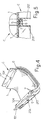
- the gutter in question is made by the injection moulding of plastics material, has for example a length of one metre, although it is to be understood that it can be produced with other dimensions, and has a body 1 of substantially semitubular section with longitudinal edges 101 having L-shaped retaining profiles of various heights, which form a widened area on the body 1 for containing the grid for pedestrian or vehicular traffic 2 (Fig. 6) which can be fixed, for example, with self-tapping screws 3 into the longitudinal slots 104 of thickened parts 4 provided externally on the bases of the said edges 101 (see below).
- Figures 1, 2, 3 and 5 show how the gutter C has transverse fins 201, made in one piece with the outer surface of the body 1 of the gutter, these fins having their ends in contact with the bases of the said edges 101 without projecting from these, and having, when viewed frontally as in Figure 6, a half-round shape which, except for the larger dimensions, substantially reproduces the internal shape of the body 1 (see Fig. 6).
- One of the said fins 201 is located at a position set back by a precise amount from one end of the gutter, as shown in Figures 1, 2, 3 and 5, and the portion of the body 1 located in front of this fin has a pair of transverse projecting ribs 5, made in one piece with the body, which terminate at the bases of the edges 101 and which form the male connector of the gutter.
- One of these ribs is substantially flush with, or set slightly back from, the end of the gutter, while the other, inner, rib is separated from the first rib by a distance D1 substantially equal to the thickness of one of the ribs in question.
- the distance D2 between this set-back rib 5 and the neighbouring fin 201 is equal to or slightly greater than the said distance D1.
- the fin 201 On the other end of the gutter C, as shown in Figures 2, 3, 4 and 5, the fin 201 has its outer face coplanar with the front of the edges 101, and an end piece 6 is formed in one piece with, and projecting from, the outer face of this fin 201, the end piece having a frontally curved shape which reproduces, with larger dimensions, the internal shape of the gutter body 1, and being provided internally with a pair of grooves 7 which form the female connector of the gutter, the inner groove having, for example, a width slightly greater than that of the other groove, whose width is slightly greater than that of the said ribs 5 of the male connector.
- the distance between the grooves 7 is such that, when the end with the ribs 5 of one gutter is inserted into the grooves 7 of an adjacent gutter, as shown in detail in Figure 5, the two gutters are interconnected in a substantially seamless way and the inner surfaces of their bodies 1 are coplanar with each other.
- the joint formed by the pair of ribs 5 which are inserted in the form of shutters into the corresponding pair of grooves 7 is of the labyrinth type and has a sinuous structure with a plurality of successive undulations which imparts exceptional qualities of rigidity and watertightness to the joint, even without the presence of silicone or other joint sealants compatible with the material from which the gutters are made. Because of the greater width of the inner groove 7 of the female connector, the joint can be made easily and correctly even if the end of the gutter or of the gutter portion (see below) with the male connector has small projections or irregularities.
- the aforesaid ribs 5 of the male connectors have a rounded profile, for example, while the grooves 7 have a trapezoidal profile, but it is to be understood that any type of profile can be used for the aforesaid purposes of connection.
- the gutter according to the invention has the property of double modularity, in the sense that it not only forms a module for constructing a channel by joining with other identical modules, but also has a modular structure itself, as a result of which it can be cut transversely at predetermined distances, so as to produce a piece which is entirely identical to the original module, except for its shorter length.
- the intrinsic modularity of the gutter module C increases the range of lengths from which a drainage channel can be constructed, since the multiples of the length of the structural module of the gutter itself can be added to the multiples of the length of one gutter.
- the body 1 of the gutter has groups G of four transverse ribs 5, located externally with a repeated and identical interval which is a submultiple of the total length of the gutter module, for example an interval of ten centimetres, the ribs in each group being separated by the distance D1 already described with reference to Figures 2 and 3, in such a way that, by cutting one of these groups of ribs in half transversely, using the ribs as a guide for the cutting saw, it is possible to shorten a gutter module while still making it terminate in a male connector opposite to the end with the female connector.
- the other gutter portion created by the said cutting operation is provided with male connectors at both ends, and can be used for other purposes (see below).
- the invention proposes to provide the gutter module with the said transverse ribs 201 additionally at the position of each group G of four ribs 5, upstream and downstream of each group, and at a distance from the group equal to the distance D2 mentioned with reference to Figures 2 and 3.
- the fins 201 of each group G of ribs are joined together by means of at least one external longitudinal link 8, positioned so that it lies flat, which must obviously be removed by a cutting operation before the said transverse cutting is carried out to shorten a module.
- the connecting link 8 can be provided at its ends with small recesses or projections to guide the cutting saw.
- each group G of ribs 5 are interconnected by means of longitudinal ribs 9 positioned on edge and clearly visible in Figures 1, 2, 3 and 6.
- U-shaped lugs 10 are provided between these ribs 9, at equal distances from the ends of the gutter, the base wall of each lug having a median slot 11, so that it can be used to fix the gutter modules in position in advance, by means of screws or securing brackets.
- the presence of these lugs 10 and the aforesaid external links 8 helps to improve the anchorage of the gutter to the cement or concrete casting into which the gutter is usually sunk to the height of the retaining edges 101, and increases the stability and distribution of this anchorage.
- Figures 1, 2 and 4 show how the said thickened areas 4 for fixing the grid 2 which covers the top of the gutter are located in the median parts of the spaces in which the said reinforcing ribs 9 lie, and how each of these areas is connected to one of these ribs and to the body 1 of the gutter by means of a median rib 204 for reinforcement and for stress distribution.
- the drainage channel formed by the combination of a plurality of gutter modules of the type in question and of corresponding portions can be sealed at the ends by a shutter-like end element S as shown in Figures 7 and 8, made by the injection moulding of plastics material, having a frontal shape which reproduces the cross section of the gutter body 1, which can be connected by inserting the curved edge of its body 12 by a shutter action into the inner groove 7 of the female connector as shown in Figure 4, and which has on its outer front a curved flange 112 projecting horizontally, which engages the inside of the end 6 and which is provided externally with a continuous rib 212, which in turn engages with the outer groove 7 of the female connector, as shown in Figure 9.
- the shutter S also engages with both of the grooves of the female connector of the gutter, so as to provide the connection with good qualities of watertightness even without the presence of sealant material, although it is still possible to use such material.
- an upper fin 312 of the shutter is positioned inside the retaining edges 101 of the gutter and at the same height, to seal the end of the space occupied by the drainage grid 2 as shown in Figure 6.
- the shutter S On the face opposite that which carries the aforesaid curved flange 112, the shutter S has a flange 412 which also projects horizontally, and which can be fitted on to the end of the gutter C provided externally with the male connector 5, mating with the inner profile of the gutter C, as shown in Figure 10.
- the upper fin 312 of the shutter S is positioned between the wings of the retaining edges 101 to seal the ends of the space occupied by the grid which finishes the top of the drainage channel.
- connection of the curved flange 412 to the inner surface of the gutter can be improved with silicone sealant and/or by the use (not shown) of two small self-tapping screws on the upper ends of this flange, to fix them to the underlying upper portions of the gutter which are less likely to be in contact with the run-off water.
- FIGs 7, 8, 9 and 10 show how a pipe connector 13, initially closed but openable by simple means, is formed in one piece, perpendicularly, and in a low position on the outer face of the shutter S which carries the curved flange 112, in such a way that the shutter S can be used either to seal the end of the channel or to make it communicate with a watercourse.
- the connector 13 When the connector 13 is open, it communicates with the lowest part of the gutter, and, in order to permit this communication and avoid the presence of standing water, the aforesaid curved flange 412 is provided with a gap 14 in its intermediate and lowest area, as shown in Figures 8 and 10.
- the invention proposes to increase the flexibility of the connection of the drainage channel to watercourses by providing, at one end of each gutter module C, for example at the end with the male connector 5 (Figs. 1, 2, 3), in a portion where the longitudinal reinforcing fins 9 are omitted between one consecutive pair of transverse fins 201, an underlying double-diameter pipe connector 15, orientated downwards, with two lateral and diametrically opposed connectors 115, which have diameters smaller than that of the connector 15 and are located in the low part of the inner section of the gutter.
- a concentric backflow prevention ring 215 is provided inside the double-diameter pipe connector 15. All the connectors 15 and 115 are initially closed, but in such a way that they can be opened or punched through by simple means if necessary.
- a cross joint X as shown in Figure 11 has been devised, and takes the form of an upwardly open shell, also made by injection moulding of plastics material, provided for example with a male connector 5 on one of its four openings, while the other three openings are provided with female connectors 6, 7.
- the four openings of the joint are separated by angles of 90° and the underside of the joint is provided with a double-diameter pipe connector 16, which is initially closed but can be opened or punched through with simple means.
- the cross joint X is also provided internally with a concentric ring 116 designed to prevent the return of water during outflow.
- the joint X has horizontal shoulders 17 to support the grid of the drainage channel placed thereon and has vertical fins 18 on these shoulders, these fins being aligned with and continuing the retaining edges 101 of the gutter modules C when one of these modules is connected to the joint in question, as illustrated for example in Figure 13 which shows the connection of the male connector 5 of the joint to the female end connector of a gutter C and which shows one of the female connectors of the joint sealed by a shutter S of the type described above with reference to Figures 7 and 8.
- the joint X can be used to form end seals of a drainage channel, with better watertightness than in the simplified solution of Figure 10, by sealing all three female connectors of the joint with corresponding shutters S.
- connection between drainage channels placed in an L-, T- or cross-shaped configuration it is possible to form connections between drainage channels placed in an L-, T- or cross-shaped configuration.
- the joint X is connected to a gutter module C, as shown for example in Figure 13, the base of the joint is substantially at the same level as the base of the gutter, thus avoiding the presence of standing water in the joint.
- a plurality of joints G can be connected to each other.
Landscapes
- Engineering & Computer Science (AREA)
- Architecture (AREA)
- Civil Engineering (AREA)
- Structural Engineering (AREA)
- Health & Medical Sciences (AREA)
- Life Sciences & Earth Sciences (AREA)
- Hydrology & Water Resources (AREA)
- Public Health (AREA)
- Water Supply & Treatment (AREA)
- Sewage (AREA)
- Dental Preparations (AREA)
Priority Applications (1)
| Application Number | Priority Date | Filing Date | Title |
|---|---|---|---|
| PL07110549T PL1870519T3 (pl) | 2006-06-21 | 2007-06-19 | Wzmocniona segmentowa studzienka kanalizacyjna |
Applications Claiming Priority (1)
| Application Number | Priority Date | Filing Date | Title |
|---|---|---|---|
| IT000055U ITBO20060055U1 (it) | 2006-06-21 | 2006-06-21 | Canaletta componibile e rinforzata |
Publications (3)
| Publication Number | Publication Date |
|---|---|
| EP1870519A2 true EP1870519A2 (de) | 2007-12-26 |
| EP1870519A3 EP1870519A3 (de) | 2011-06-22 |
| EP1870519B1 EP1870519B1 (de) | 2015-02-11 |
Family
ID=38475983
Family Applications (1)
| Application Number | Title | Priority Date | Filing Date |
|---|---|---|---|
| EP07110549.8A Active EP1870519B1 (de) | 2006-06-21 | 2007-06-19 | Verstärkte Abflussrinne |
Country Status (4)
| Country | Link |
|---|---|
| EP (1) | EP1870519B1 (de) |
| ES (1) | ES2542895T3 (de) |
| IT (1) | ITBO20060055U1 (de) |
| PL (1) | PL1870519T3 (de) |
Cited By (12)
| Publication number | Priority date | Publication date | Assignee | Title |
|---|---|---|---|---|
| EP2261429A1 (de) * | 2009-06-08 | 2010-12-15 | Friedrich Wolfarth GmbH & Co. KG | Rinnenelement |
| EP2372021A1 (de) | 2010-03-24 | 2011-10-05 | EUR.EX S.r.l. | Modulares und leicht zusammenbaubares Gitterabdeckstück für Abflusskanäle |
| WO2014184547A1 (en) * | 2013-05-17 | 2014-11-20 | Greenblue Urban Ltd | A modular drainage system |
| CZ307338B6 (cs) * | 2017-03-09 | 2018-06-13 | ÄŚVUT v Praze, Fakulta stavebnĂ | Příkopová tvarovka z recyklovaného plastu |
| RU183515U1 (ru) * | 2018-07-02 | 2018-09-25 | Сергей Иванович Барышников | Лоток водоотводной из композиционных материалов |
| RU186608U1 (ru) * | 2018-10-12 | 2019-01-24 | Евгений Сергеевич Васюткин | Лоток водоотводной |
| FR3074817A1 (fr) * | 2017-12-12 | 2019-06-14 | Hauraton France | Element modulaire de caniveau |
| US10543898B2 (en) | 2015-11-30 | 2020-01-28 | Airbus Operations Limited | Dual-purpose locking and folding arrangement for an aircraft wing tip device |
| WO2020169216A1 (de) * | 2019-02-21 | 2020-08-27 | Aco Severin Ahlmann Gmbh & Co. Kg | Entwässerungssystem, einheiten und verfahren |
| CN114855968A (zh) * | 2022-06-02 | 2022-08-05 | 清华大学山西清洁能源研究院 | 一种用于太阳能电站的防水排水结构 |
| NL2039966A (en) * | 2023-09-26 | 2025-03-27 | Tbs Sva Groep B V | Infrastructural gutter module |
| US12662368B2 (en) * | 2023-12-15 | 2026-06-23 | Fibrelite Composites Limited | Trenches for delivering service supplies |
Families Citing this family (1)
| Publication number | Priority date | Publication date | Assignee | Title |
|---|---|---|---|---|
| DE102022113081A1 (de) * | 2022-05-24 | 2023-11-30 | Aco Ahlmann Se & Co. Kg | Rinnenelement zum Entwässern |
Citations (3)
| Publication number | Priority date | Publication date | Assignee | Title |
|---|---|---|---|---|
| US3156099A (en) | 1961-03-10 | 1964-11-10 | John J Dailey | Fluid distribution elements |
| EP0542701B1 (de) | 1991-11-11 | 1996-03-06 | FIRST PLAST S.r.l. | Modulares Kanalelement für Entwässerungsrinnen |
| EP0789111A1 (de) | 1996-02-09 | 1997-08-13 | EDIL PLAST S.r.l. | Modulrinne für Abflusskanäle |
Family Cites Families (1)
| Publication number | Priority date | Publication date | Assignee | Title |
|---|---|---|---|---|
| US6692186B1 (en) * | 2002-12-11 | 2004-02-17 | Fast Ditch, Inc. | Apparatus and method for transporting water |
-
2006
- 2006-06-21 IT IT000055U patent/ITBO20060055U1/it unknown
-
2007
- 2007-06-19 ES ES07110549.8T patent/ES2542895T3/es active Active
- 2007-06-19 EP EP07110549.8A patent/EP1870519B1/de active Active
- 2007-06-19 PL PL07110549T patent/PL1870519T3/pl unknown
Patent Citations (3)
| Publication number | Priority date | Publication date | Assignee | Title |
|---|---|---|---|---|
| US3156099A (en) | 1961-03-10 | 1964-11-10 | John J Dailey | Fluid distribution elements |
| EP0542701B1 (de) | 1991-11-11 | 1996-03-06 | FIRST PLAST S.r.l. | Modulares Kanalelement für Entwässerungsrinnen |
| EP0789111A1 (de) | 1996-02-09 | 1997-08-13 | EDIL PLAST S.r.l. | Modulrinne für Abflusskanäle |
Cited By (18)
| Publication number | Priority date | Publication date | Assignee | Title |
|---|---|---|---|---|
| EP2261429A1 (de) * | 2009-06-08 | 2010-12-15 | Friedrich Wolfarth GmbH & Co. KG | Rinnenelement |
| EP2372021A1 (de) | 2010-03-24 | 2011-10-05 | EUR.EX S.r.l. | Modulares und leicht zusammenbaubares Gitterabdeckstück für Abflusskanäle |
| US8469631B2 (en) | 2010-03-24 | 2013-06-25 | Eur.Ex S.R.L. | Modular and easy to assemble grilled cover piece for drainage channels |
| WO2014184547A1 (en) * | 2013-05-17 | 2014-11-20 | Greenblue Urban Ltd | A modular drainage system |
| GB2517895A (en) * | 2013-05-17 | 2015-03-11 | Greenblue Urban Ltd | A modular drainage system |
| US10543898B2 (en) | 2015-11-30 | 2020-01-28 | Airbus Operations Limited | Dual-purpose locking and folding arrangement for an aircraft wing tip device |
| CZ307338B6 (cs) * | 2017-03-09 | 2018-06-13 | ÄŚVUT v Praze, Fakulta stavebnĂ | Příkopová tvarovka z recyklovaného plastu |
| FR3074817A1 (fr) * | 2017-12-12 | 2019-06-14 | Hauraton France | Element modulaire de caniveau |
| RU183515U1 (ru) * | 2018-07-02 | 2018-09-25 | Сергей Иванович Барышников | Лоток водоотводной из композиционных материалов |
| RU186608U1 (ru) * | 2018-10-12 | 2019-01-24 | Евгений Сергеевич Васюткин | Лоток водоотводной |
| WO2020169216A1 (de) * | 2019-02-21 | 2020-08-27 | Aco Severin Ahlmann Gmbh & Co. Kg | Entwässerungssystem, einheiten und verfahren |
| CN113474511A (zh) * | 2019-02-21 | 2021-10-01 | 亚科赛福林阿尔曼有限公司 | 排水系统、单元和方法 |
| CN113474511B (zh) * | 2019-02-21 | 2023-09-26 | 亚科阿尔曼欧洲两合公司 | 排水系统、单元和方法 |
| US11933034B2 (en) | 2019-02-21 | 2024-03-19 | Aco Ahlmann Se & Co. Kg | Drainage system, drainage units, and methods |
| CN114855968A (zh) * | 2022-06-02 | 2022-08-05 | 清华大学山西清洁能源研究院 | 一种用于太阳能电站的防水排水结构 |
| NL2039966A (en) * | 2023-09-26 | 2025-03-27 | Tbs Sva Groep B V | Infrastructural gutter module |
| NL2035894B1 (en) * | 2023-09-26 | 2025-04-01 | Tbs Sva Groep B V | Infrastructural gutter module |
| US12662368B2 (en) * | 2023-12-15 | 2026-06-23 | Fibrelite Composites Limited | Trenches for delivering service supplies |
Also Published As
| Publication number | Publication date |
|---|---|
| ES2542895T3 (es) | 2015-08-12 |
| EP1870519A3 (de) | 2011-06-22 |
| PL1870519T3 (pl) | 2015-07-31 |
| ITBO20060055U1 (it) | 2007-12-22 |
| EP1870519B1 (de) | 2015-02-11 |
Similar Documents
| Publication | Publication Date | Title |
|---|---|---|
| US5729937A (en) | Modular gutter for drainage channels | |
| EP1870519B1 (de) | Verstärkte Abflussrinne | |
| CA2532923A1 (en) | Water drainage component | |
| US5890837A (en) | Multiple compartment drainage conduit with diverters | |
| KR101559751B1 (ko) | 거푸집이 필요없는 조립식 옹벽 | |
| CN103806359A (zh) | 一种排水路缘石 | |
| ES2295512T3 (es) | Sistema de drenaje de canal ancho. | |
| EP0033651B1 (de) | Oberflächenentwässerungssystem | |
| RU2200786C1 (ru) | Элемент поверхностного дождеотводного канала | |
| US4367974A (en) | Surface drainage system and cover member for use therein | |
| US20090202302A1 (en) | Trench drain system | |
| CN220318293U (zh) | 装配式公路工程排水槽 | |
| EP1520942B1 (de) | Oberflächenentwässerung | |
| KR20240034473A (ko) | 복열 불투수성 돌출턱을 갖는 방수턱의 시공 방법 및 그 구조 | |
| KR20140020510A (ko) | 측구 | |
| GB2315792A (en) | Kerb drainage system | |
| CN222025208U (zh) | 一种用于收集道路雨水的组合型排水沟 | |
| CN220538298U (zh) | 装配式纤维增强复合材料公路工程排水槽路 | |
| KR102804953B1 (ko) | 수생태계 저영향개발(lid)을 위한 경사배수공 빗물받이 덮개 수로관 시스템 | |
| CN220953031U (zh) | 一种应用于中小型渠道的混凝土桥涵 | |
| KR100954800B1 (ko) | 배수로가 형성된 경계부재 | |
| RU2731759C1 (ru) | Водосточный железобетонный лоток и канал | |
| JP7499163B2 (ja) | 貯水型側溝およびそれを用いた貯水型側溝設備 | |
| EP3270026A1 (de) | Verfahren zur bereitstellung einer flüssigkeitsdichten verbindung zwischen teilen und struktur mit einer derartigen verbindung | |
| WO2008090392A1 (en) | Crossings, especially home driveway crossings |
Legal Events
| Date | Code | Title | Description |
|---|---|---|---|
| PUAI | Public reference made under article 153(3) epc to a published international application that has entered the european phase |
Free format text: ORIGINAL CODE: 0009012 |
|
| AK | Designated contracting states |
Kind code of ref document: A2 Designated state(s): AT BE BG CH CY CZ DE DK EE ES FI FR GB GR HU IE IS IT LI LT LU LV MC MT NL PL PT RO SE SI SK TR |
|
| AX | Request for extension of the european patent |
Extension state: AL BA HR MK YU |
|
| PUAL | Search report despatched |
Free format text: ORIGINAL CODE: 0009013 |
|
| AK | Designated contracting states |
Kind code of ref document: A3 Designated state(s): AT BE BG CH CY CZ DE DK EE ES FI FR GB GR HU IE IS IT LI LT LU LV MC MT NL PL PT RO SE SI SK TR |
|
| AX | Request for extension of the european patent |
Extension state: AL BA HR MK RS |
|
| 17P | Request for examination filed |
Effective date: 20111018 |
|
| AKX | Designation fees paid |
Designated state(s): AT BE BG CH CY CZ DE DK EE ES FI FR GB GR HU IE IS IT LI LT LU LV MC MT NL PL PT RO SE SI SK TR |
|
| GRAP | Despatch of communication of intention to grant a patent |
Free format text: ORIGINAL CODE: EPIDOSNIGR1 |
|
| INTG | Intention to grant announced |
Effective date: 20140904 |
|
| GRAS | Grant fee paid |
Free format text: ORIGINAL CODE: EPIDOSNIGR3 |
|
| GRAA | (expected) grant |
Free format text: ORIGINAL CODE: 0009210 |
|
| AK | Designated contracting states |
Kind code of ref document: B1 Designated state(s): AT BE BG CH CY CZ DE DK EE ES FI FR GB GR HU IE IS IT LI LT LU LV MC MT NL PL PT RO SE SI SK TR |
|
| REG | Reference to a national code |
Ref country code: GB Ref legal event code: FG4D |
|
| REG | Reference to a national code |
Ref country code: CH Ref legal event code: EP |
|
| REG | Reference to a national code |
Ref country code: IE Ref legal event code: FG4D |
|
| REG | Reference to a national code |
Ref country code: AT Ref legal event code: REF Ref document number: 709981 Country of ref document: AT Kind code of ref document: T Effective date: 20150315 |
|
| REG | Reference to a national code |
Ref country code: DE Ref legal event code: R096 Ref document number: 602007040224 Country of ref document: DE Effective date: 20150326 |
|
| REG | Reference to a national code |
Ref country code: NL Ref legal event code: VDEP Effective date: 20150211 |
|
| REG | Reference to a national code |
Ref country code: AT Ref legal event code: MK05 Ref document number: 709981 Country of ref document: AT Kind code of ref document: T Effective date: 20150211 |
|
| REG | Reference to a national code |
Ref country code: LT Ref legal event code: MG4D |
|
| PG25 | Lapsed in a contracting state [announced via postgrant information from national office to epo] |
Ref country code: LT Free format text: LAPSE BECAUSE OF FAILURE TO SUBMIT A TRANSLATION OF THE DESCRIPTION OR TO PAY THE FEE WITHIN THE PRESCRIBED TIME-LIMIT Effective date: 20150211 Ref country code: SE Free format text: LAPSE BECAUSE OF FAILURE TO SUBMIT A TRANSLATION OF THE DESCRIPTION OR TO PAY THE FEE WITHIN THE PRESCRIBED TIME-LIMIT Effective date: 20150211 Ref country code: FI Free format text: LAPSE BECAUSE OF FAILURE TO SUBMIT A TRANSLATION OF THE DESCRIPTION OR TO PAY THE FEE WITHIN THE PRESCRIBED TIME-LIMIT Effective date: 20150211 |
|
| REG | Reference to a national code |
Ref country code: PL Ref legal event code: T3 |
|
| REG | Reference to a national code |
Ref country code: ES Ref legal event code: FG2A Ref document number: 2542895 Country of ref document: ES Kind code of ref document: T3 Effective date: 20150812 |
|
| PG25 | Lapsed in a contracting state [announced via postgrant information from national office to epo] |
Ref country code: LV Free format text: LAPSE BECAUSE OF FAILURE TO SUBMIT A TRANSLATION OF THE DESCRIPTION OR TO PAY THE FEE WITHIN THE PRESCRIBED TIME-LIMIT Effective date: 20150211 Ref country code: AT Free format text: LAPSE BECAUSE OF FAILURE TO SUBMIT A TRANSLATION OF THE DESCRIPTION OR TO PAY THE FEE WITHIN THE PRESCRIBED TIME-LIMIT Effective date: 20150211 Ref country code: GR Free format text: LAPSE BECAUSE OF FAILURE TO SUBMIT A TRANSLATION OF THE DESCRIPTION OR TO PAY THE FEE WITHIN THE PRESCRIBED TIME-LIMIT Effective date: 20150512 Ref country code: NL Free format text: LAPSE BECAUSE OF FAILURE TO SUBMIT A TRANSLATION OF THE DESCRIPTION OR TO PAY THE FEE WITHIN THE PRESCRIBED TIME-LIMIT Effective date: 20150211 Ref country code: IS Free format text: LAPSE BECAUSE OF FAILURE TO SUBMIT A TRANSLATION OF THE DESCRIPTION OR TO PAY THE FEE WITHIN THE PRESCRIBED TIME-LIMIT Effective date: 20150611 |
|
| PG25 | Lapsed in a contracting state [announced via postgrant information from national office to epo] |
Ref country code: SK Free format text: LAPSE BECAUSE OF FAILURE TO SUBMIT A TRANSLATION OF THE DESCRIPTION OR TO PAY THE FEE WITHIN THE PRESCRIBED TIME-LIMIT Effective date: 20150211 Ref country code: CZ Free format text: LAPSE BECAUSE OF FAILURE TO SUBMIT A TRANSLATION OF THE DESCRIPTION OR TO PAY THE FEE WITHIN THE PRESCRIBED TIME-LIMIT Effective date: 20150211 Ref country code: EE Free format text: LAPSE BECAUSE OF FAILURE TO SUBMIT A TRANSLATION OF THE DESCRIPTION OR TO PAY THE FEE WITHIN THE PRESCRIBED TIME-LIMIT Effective date: 20150211 Ref country code: DK Free format text: LAPSE BECAUSE OF FAILURE TO SUBMIT A TRANSLATION OF THE DESCRIPTION OR TO PAY THE FEE WITHIN THE PRESCRIBED TIME-LIMIT Effective date: 20150211 Ref country code: RO Free format text: LAPSE BECAUSE OF FAILURE TO SUBMIT A TRANSLATION OF THE DESCRIPTION OR TO PAY THE FEE WITHIN THE PRESCRIBED TIME-LIMIT Effective date: 20150211 |
|
| REG | Reference to a national code |
Ref country code: DE Ref legal event code: R097 Ref document number: 602007040224 Country of ref document: DE |
|
| PLBE | No opposition filed within time limit |
Free format text: ORIGINAL CODE: 0009261 |
|
| STAA | Information on the status of an ep patent application or granted ep patent |
Free format text: STATUS: NO OPPOSITION FILED WITHIN TIME LIMIT |
|
| 26N | No opposition filed |
Effective date: 20151112 |
|
| PG25 | Lapsed in a contracting state [announced via postgrant information from national office to epo] |
Ref country code: MC Free format text: LAPSE BECAUSE OF FAILURE TO SUBMIT A TRANSLATION OF THE DESCRIPTION OR TO PAY THE FEE WITHIN THE PRESCRIBED TIME-LIMIT Effective date: 20150211 |
|
| REG | Reference to a national code |
Ref country code: CH Ref legal event code: PL |
|
| PG25 | Lapsed in a contracting state [announced via postgrant information from national office to epo] |
Ref country code: LU Free format text: LAPSE BECAUSE OF FAILURE TO SUBMIT A TRANSLATION OF THE DESCRIPTION OR TO PAY THE FEE WITHIN THE PRESCRIBED TIME-LIMIT Effective date: 20150619 Ref country code: SI Free format text: LAPSE BECAUSE OF FAILURE TO SUBMIT A TRANSLATION OF THE DESCRIPTION OR TO PAY THE FEE WITHIN THE PRESCRIBED TIME-LIMIT Effective date: 20150211 |
|
| PG25 | Lapsed in a contracting state [announced via postgrant information from national office to epo] |
Ref country code: LI Free format text: LAPSE BECAUSE OF NON-PAYMENT OF DUE FEES Effective date: 20150630 Ref country code: CH Free format text: LAPSE BECAUSE OF NON-PAYMENT OF DUE FEES Effective date: 20150630 |
|
| PG25 | Lapsed in a contracting state [announced via postgrant information from national office to epo] |
Ref country code: BE Free format text: LAPSE BECAUSE OF FAILURE TO SUBMIT A TRANSLATION OF THE DESCRIPTION OR TO PAY THE FEE WITHIN THE PRESCRIBED TIME-LIMIT Effective date: 20150211 |
|
| REG | Reference to a national code |
Ref country code: FR Ref legal event code: PLFP Year of fee payment: 10 |
|
| PG25 | Lapsed in a contracting state [announced via postgrant information from national office to epo] |
Ref country code: MT Free format text: LAPSE BECAUSE OF FAILURE TO SUBMIT A TRANSLATION OF THE DESCRIPTION OR TO PAY THE FEE WITHIN THE PRESCRIBED TIME-LIMIT Effective date: 20150211 |
|
| PG25 | Lapsed in a contracting state [announced via postgrant information from national office to epo] |
Ref country code: BG Free format text: LAPSE BECAUSE OF FAILURE TO SUBMIT A TRANSLATION OF THE DESCRIPTION OR TO PAY THE FEE WITHIN THE PRESCRIBED TIME-LIMIT Effective date: 20150211 Ref country code: HU Free format text: LAPSE BECAUSE OF FAILURE TO SUBMIT A TRANSLATION OF THE DESCRIPTION OR TO PAY THE FEE WITHIN THE PRESCRIBED TIME-LIMIT; INVALID AB INITIO Effective date: 20070619 |
|
| REG | Reference to a national code |
Ref country code: FR Ref legal event code: PLFP Year of fee payment: 11 |
|
| PG25 | Lapsed in a contracting state [announced via postgrant information from national office to epo] |
Ref country code: CY Free format text: LAPSE BECAUSE OF FAILURE TO SUBMIT A TRANSLATION OF THE DESCRIPTION OR TO PAY THE FEE WITHIN THE PRESCRIBED TIME-LIMIT Effective date: 20150211 |
|
| PG25 | Lapsed in a contracting state [announced via postgrant information from national office to epo] |
Ref country code: TR Free format text: LAPSE BECAUSE OF FAILURE TO SUBMIT A TRANSLATION OF THE DESCRIPTION OR TO PAY THE FEE WITHIN THE PRESCRIBED TIME-LIMIT Effective date: 20150211 |
|
| REG | Reference to a national code |
Ref country code: FR Ref legal event code: PLFP Year of fee payment: 12 |
|
| PG25 | Lapsed in a contracting state [announced via postgrant information from national office to epo] |
Ref country code: PT Free format text: LAPSE BECAUSE OF FAILURE TO SUBMIT A TRANSLATION OF THE DESCRIPTION OR TO PAY THE FEE WITHIN THE PRESCRIBED TIME-LIMIT Effective date: 20150211 |
|
| PGFP | Annual fee paid to national office [announced via postgrant information from national office to epo] |
Ref country code: IE Payment date: 20180626 Year of fee payment: 12 |
|
| REG | Reference to a national code |
Ref country code: DE Ref legal event code: R082 Ref document number: 602007040224 Country of ref document: DE Representative=s name: MEISSNER BOLTE PATENTANWAELTE RECHTSANWAELTE P, DE |
|
| GBPC | Gb: european patent ceased through non-payment of renewal fee |
Effective date: 20190619 |
|
| PG25 | Lapsed in a contracting state [announced via postgrant information from national office to epo] |
Ref country code: IE Free format text: LAPSE BECAUSE OF NON-PAYMENT OF DUE FEES Effective date: 20190619 Ref country code: GB Free format text: LAPSE BECAUSE OF NON-PAYMENT OF DUE FEES Effective date: 20190619 |
|
| PGFP | Annual fee paid to national office [announced via postgrant information from national office to epo] |
Ref country code: DE Payment date: 20240628 Year of fee payment: 18 |
|
| PGFP | Annual fee paid to national office [announced via postgrant information from national office to epo] |
Ref country code: ES Payment date: 20240708 Year of fee payment: 18 |
|
| PGFP | Annual fee paid to national office [announced via postgrant information from national office to epo] |
Ref country code: PL Payment date: 20250613 Year of fee payment: 19 |
|
| PGFP | Annual fee paid to national office [announced via postgrant information from national office to epo] |
Ref country code: FR Payment date: 20250630 Year of fee payment: 19 |
|
| PGFP | Annual fee paid to national office [announced via postgrant information from national office to epo] |
Ref country code: IT Payment date: 20250630 Year of fee payment: 19 |
|
| REG | Reference to a national code |
Ref country code: DE Ref legal event code: R119 Ref document number: 602007040224 Country of ref document: DE |
|
| PG25 | Lapsed in a contracting state [announced via postgrant information from national office to epo] |
Ref country code: DE Free format text: LAPSE BECAUSE OF NON-PAYMENT OF DUE FEES Effective date: 20260101 |
|
| REG | Reference to a national code |
Ref country code: ES Ref legal event code: FD2A Effective date: 20260731 |