EP1870617A2 - Dispositif d'actionnement pour un engrenage d'un véhicule - Google Patents
Dispositif d'actionnement pour un engrenage d'un véhicule Download PDFInfo
- Publication number
- EP1870617A2 EP1870617A2 EP07007671A EP07007671A EP1870617A2 EP 1870617 A2 EP1870617 A2 EP 1870617A2 EP 07007671 A EP07007671 A EP 07007671A EP 07007671 A EP07007671 A EP 07007671A EP 1870617 A2 EP1870617 A2 EP 1870617A2
- Authority
- EP
- European Patent Office
- Prior art keywords
- spindle
- actuating device
- coupling member
- drive
- movement
- Prior art date
- Legal status (The legal status is an assumption and is not a legal conclusion. Google has not performed a legal analysis and makes no representation as to the accuracy of the status listed.)
- Granted
Links
Images


Classifications
-
- F—MECHANICAL ENGINEERING; LIGHTING; HEATING; WEAPONS; BLASTING
- F16—ENGINEERING ELEMENTS AND UNITS; GENERAL MEASURES FOR PRODUCING AND MAINTAINING EFFECTIVE FUNCTIONING OF MACHINES OR INSTALLATIONS; THERMAL INSULATION IN GENERAL
- F16H—GEARING
- F16H61/00—Control functions within control units of change-speed- or reversing-gearings for conveying rotary motion ; Control of exclusively fluid gearing, friction gearing, gearings with endless flexible members or other particular types of gearing
- F16H61/26—Generation or transmission of movements for final actuating mechanisms
- F16H61/28—Generation or transmission of movements for final actuating mechanisms with at least one movement of the final actuating mechanism being caused by a non-mechanical force, e.g. power-assisted
- F16H61/32—Electric motors , actuators or related electrical control means therefor
-
- F—MECHANICAL ENGINEERING; LIGHTING; HEATING; WEAPONS; BLASTING
- F16—ENGINEERING ELEMENTS AND UNITS; GENERAL MEASURES FOR PRODUCING AND MAINTAINING EFFECTIVE FUNCTIONING OF MACHINES OR INSTALLATIONS; THERMAL INSULATION IN GENERAL
- F16H—GEARING
- F16H61/00—Control functions within control units of change-speed- or reversing-gearings for conveying rotary motion ; Control of exclusively fluid gearing, friction gearing, gearings with endless flexible members or other particular types of gearing
- F16H61/26—Generation or transmission of movements for final actuating mechanisms
- F16H61/28—Generation or transmission of movements for final actuating mechanisms with at least one movement of the final actuating mechanism being caused by a non-mechanical force, e.g. power-assisted
- F16H2061/2876—Racks
-
- F—MECHANICAL ENGINEERING; LIGHTING; HEATING; WEAPONS; BLASTING
- F16—ENGINEERING ELEMENTS AND UNITS; GENERAL MEASURES FOR PRODUCING AND MAINTAINING EFFECTIVE FUNCTIONING OF MACHINES OR INSTALLATIONS; THERMAL INSULATION IN GENERAL
- F16H—GEARING
- F16H61/00—Control functions within control units of change-speed- or reversing-gearings for conveying rotary motion ; Control of exclusively fluid gearing, friction gearing, gearings with endless flexible members or other particular types of gearing
- F16H61/26—Generation or transmission of movements for final actuating mechanisms
- F16H61/28—Generation or transmission of movements for final actuating mechanisms with at least one movement of the final actuating mechanism being caused by a non-mechanical force, e.g. power-assisted
- F16H2061/2884—Screw-nut devices
-
- F—MECHANICAL ENGINEERING; LIGHTING; HEATING; WEAPONS; BLASTING
- F16—ENGINEERING ELEMENTS AND UNITS; GENERAL MEASURES FOR PRODUCING AND MAINTAINING EFFECTIVE FUNCTIONING OF MACHINES OR INSTALLATIONS; THERMAL INSULATION IN GENERAL
- F16H—GEARING
- F16H63/00—Control outputs from the control unit to change-speed- or reversing-gearings for conveying rotary motion or to other devices than the final output mechanism
- F16H63/02—Final output mechanisms therefor; Actuating means for the final output mechanisms
- F16H63/08—Multiple final output mechanisms being moved by a single common final actuating mechanism
- F16H63/20—Multiple final output mechanisms being moved by a single common final actuating mechanism with preselection and subsequent movement of each final output mechanism by movement of the final actuating mechanism in two different ways, e.g. guided by a shift gate
-
- Y—GENERAL TAGGING OF NEW TECHNOLOGICAL DEVELOPMENTS; GENERAL TAGGING OF CROSS-SECTIONAL TECHNOLOGIES SPANNING OVER SEVERAL SECTIONS OF THE IPC; TECHNICAL SUBJECTS COVERED BY FORMER USPC CROSS-REFERENCE ART COLLECTIONS [XRACs] AND DIGESTS
- Y10—TECHNICAL SUBJECTS COVERED BY FORMER USPC
- Y10T—TECHNICAL SUBJECTS COVERED BY FORMER US CLASSIFICATION
- Y10T74/00—Machine element or mechanism
- Y10T74/18—Mechanical movements
- Y10T74/18568—Reciprocating or oscillating to or from alternating rotary
- Y10T74/18576—Reciprocating or oscillating to or from alternating rotary including screw and nut
- Y10T74/18624—Plural inputs, single output
- Y10T74/18632—Plural nuts driving shaft
-
- Y—GENERAL TAGGING OF NEW TECHNOLOGICAL DEVELOPMENTS; GENERAL TAGGING OF CROSS-SECTIONAL TECHNOLOGIES SPANNING OVER SEVERAL SECTIONS OF THE IPC; TECHNICAL SUBJECTS COVERED BY FORMER USPC CROSS-REFERENCE ART COLLECTIONS [XRACs] AND DIGESTS
- Y10—TECHNICAL SUBJECTS COVERED BY FORMER USPC
- Y10T—TECHNICAL SUBJECTS COVERED BY FORMER US CLASSIFICATION
- Y10T74/00—Machine element or mechanism
- Y10T74/20—Control lever and linkage systems
- Y10T74/20012—Multiple controlled elements
- Y10T74/20018—Transmission control
- Y10T74/2003—Electrical actuator
Definitions
- the invention relates to an actuating device for a transmission of a vehicle, in particular a commercial vehicle, bus or the like., Having the features in the preamble of claim 1.
- Known actuators of this type have a cross slide, which has a separate spindle motor for the displacement of the longitudinal slide in the longitudinal direction and also for the transverse displacement of the cross slide in the transverse direction another associated spindle motor, which is like the cross slide on the longitudinal slide and must be dragged with this.
- Such an actuating device is complicated and complicated. In order to always display the respective position of the two spindle motors, two absolute value sensors are required in each case. This too is expensive. Another disadvantage is that such an actuator has a large volume and requires correspondingly large installation conditions.
- the invention has for its object to provide an actuator of the type mentioned, the simple, compact, inexpensive and is designed easily and allows installation even in confined spaces.
- This inventive design of the actuator can be achieved higher working speeds for the adjusting movement of a gear shift cam. There are only small to be accelerated and retarded masses in the form of rotatably driven spindle nuts and the axial spindle, which makes much faster speeds possible.
- Another advantage is that the actuator is compact, has a low weight and is much cheaper to produce than known devices of this kind. can be used in terms of modular drives in terms of drives on existing drive units. It is also advantageous that, in terms of size, e.g. the travel paths in the longitudinal and / or transverse direction is free and can make them free by appropriate programming of the central control of the drive motors serving control device.
- the actuator is quickly and easily adaptable to different control tasks. Since the actuator particularly compact and compact builds, it is also suitable for installation in confined spaces.
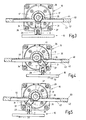
- FIGS. 1 to 4 schematically show a part 10 of interest here of a transmission of a vehicle, in particular a utility vehicle, bus or the like. shown having an upstanding control cam 11.
- the switching cam 11 has in particular the shape of a mecanicvielkants, eg Contemporaryvierkants.
- Fig. 1 is only indicated by dashed lines, that this switching cam 11 is displaced to the corresponding actuation of the transmission not shown in a plane with longitudinal shift rails 12 and transverse shift rails 13.
- the switching cam 11 In the position shown in Fig. 1, the switching cam 11 is in a transverse switching path 13. This corresponds to a particular transmission circuit in a predetermined gear.
- the switching cam 11 is moved by transverse movement from the transverse shift path 13 out in the longitudinal shift path 12 and along the latter in the longitudinal direction forward or backward moves until the desired assigned to switching gear, other, transverse switching path 13 is reached. Then, the switching cam 11 is retracted by transverse movement in this new transverse switching path 13.
- the cross slide has a guided along a guide carrier longitudinal slide, which is actuated by means of a seated on the guide carrier spindle motor for the longitudinal movement.
- the longitudinal carriage is a carrier of a cross slide and also a spindle motor associated with this cross slide. During the longitudinal movement of the longitudinal slide of the cross slide and its spindle motor are dragged.
- the cross slide is a carrier of a connecting element which is in communication with the switching cam for switching the transmission.
- Such an actuator by means of cross slide and two separate spindle motors is expensive. It requires a lot of space and a correspondingly large construction costs. For the positioning movements two absolute value sensors are required to signal the respective position of the two spindle motors.
- the invention provides for this a drive means 16 with spindle 17, which has two axially adjacent threaded portions 18 and 19, wherein the thread pitch of these threaded portions 18,19 is in opposite directions.
- the threaded portion 18 has e.g. Left-hand thread, while the threaded portion 19 has corresponding right-hand thread.
- the conditions can also be reversed.
- the one threaded portion 18 is a spindle nut 20 and the other threaded portion 19 associated with a corresponding spindle nut 21.
- the spindle nuts 20, 21 are provided with corresponding internal thread and sit on the respective threaded portion 18 and 19.
- Each spindle nut 20, 21 is rotatably connected to a spindle 17 coaxial sleeve 22 and 23 and by means of a bearing 24 and 25 in relation rotatably mounted on a housing 26.
- Each spindle nut 20, 21 is assigned to the rotary drive a respective drive motor 27 and 28, which is in particular designed as an electric motor.
- the sleeve 22 or 23 may be carrier of the rotor of the drive motor 27 or 28 or is itself designed as a rotor.
- Each spindle nut 20, 21 is rotatable by means of the associated drive motor 27 or 28, but arranged axially immovable, so that a rotational actuation of the respective spindle nut 20 or 21 leads to a translational drive and / or rotary drive of the spindle 17. If both drive motors 27 and 28 in the same direction of rotation and at the same speed drive the respective associated spindle nut 20, 21, this has a pure rotational movement of the spindle 17 in one or the other direction result, which depends on the respective direction of rotation during the synchronization of the drive motors 27, 28 depends.
- the spindle 17 is translationally driven in the direction of arrow 15 in one or the other direction, which depends on the direction of rotation.
- the drive means 16 has a switching cam 11 engaging and this in the longitudinal direction according to the longitudinal switching path 12, namely forward or backward, and in the transverse direction according to the transverse switching paths 13 moving coupling member 29 which is actuated by means of the spindle 17.
- the spindle 17 is provided on the output side in the region of the left in Fig. 2 end 30 with a motion converter 31, by means of which the rotational movement of the spindle 17 in one or the other direction in a translational transverse movement of the coupling member 29 in one or the other transverse direction is changeable , By means of the motion converter 31, the output rotational movement of the spindle 17 is thus converted in rotation in the one direction in a translational transverse movement, for. according to arrow 32 in Fig. 4 to the right.
- Fig. 3 shows a position of the movement converter 31, which corresponds to a movement of the spindle 17 in the longitudinal direction according to arrow 15 forward or backward. Also, the switching cam 11 is positively entrained via the coupling member 29 and moved accordingly. The motion converter 31 is thus entrained in the longitudinal direction with the spindle 17, wherein the longitudinal movement has a corresponding longitudinal movement of the coupling member 29 and switching cam 11 result.
- an approximately radially directed driver 34 is on the output side rotatably connected, on which the coupling member 29 engages.
- the radially projecting driver 34 may be held on a sleeve 35, which in turn is fixedly connected to the spindle 17.
- the driver 34 and the coupling member 29 are connected by means of a hinge 36, for example a bolt 37, pivotally connected to each other, about an axis of the spindle 17 approximately parallel axis.
- the coupling member 29 is in the Abretesschwenkterrorism the spindle 17 relative to the switching cam 11 approximately at right angles to the switching plane while maintaining the actuating engagement with the switching cam 11 slidably.
- the coupling member 29 is fitted in the drawings from above on the control cam 11 and a relative movement of the coupling member 29 in this direction relative to the control cam 11 is possible.
- the coupling member 29 may have a polyhedron, eg inner square, which is adapted to a corresponding outer polygon, for example, external square, the control cam 11 and by plugging it with this form-fitting coupled.
- the driver 34 on the one hand and the coupling member 29 on the other hand connected via a coupling which at one part, e.g. on the coupling member 29, a slot and on the other part, e.g. on the driver 34, an engaging in the slot cam.
- the vertical relative movement takes place between the driver 34 and the coupling member 29 and not, as shown in the first embodiment, between the coupling member 29 and the switching cam eleventh
- the spindle 17 may be formed with particular advantage as a ball screw, which operates smoothly and with low friction.
- the drive device 16 has at one end of the housing 26, in particular on the left in Fig. 1 and 2 housing end, on the housing 26 approximately frontally attacking, approximately cover-like fastening part 40 which is fixedly connected to the drive means 16. With this fastening part 40, the drive device 16 can be placed on a not further shown gear housing from above and detachably fastened thereto.
- the spindle 17 continues into the fastening part 40.
- the motion converter 31 is arranged in the fastening part 40, wherein the radial driver 34 and the coupling member 29 from the fastening part 40 in the drawings down protrude.
- the fastening part 40 has an extension of the spindle 17 and approximately coaxially to the longitudinal central axis extending tubular member 41 in which the spindle 17 is guided with the sleeve 35 which carries the driver 34.
- the tube part 41 of the fastening part 40 extends over a circumferential angle, which is greater than 180 ° and less than 360 °, such that the sleeve 35 with the spindle 17 over a circumferential angle greater than 180 ° from the tube part 41 and against slipping out in Fig. 3 to 5 are secured down.
- the tube part 41 forms a longitudinal guide with bearing property transversely to the longitudinal central axis of the spindle 17 and allows a bilateral pivotal movement of the driver 34 to.
- the fastening part 40 is formed as a hollow plate 42 which is open on a in Fig. 2 to 5 below extending broadside 43 and in the region of the opposite other broad side 44, the tube part 41.
- the drive device 16 is equipped with a control device, not shown, by means of which the drive motors 27, 28 are controlled in terms of their speed, direction of rotation and / or, if necessary, in terms of their drive torque.
- Fig. 2 is schematically indicated that the drive motor 27 and the drive motor 28 each have a rotative sensor 45 and 46, respectively, via which the revolutions of the associated spindle nut 20 and 21 are detected.
- the spindle 17 is associated with an absolute value linear sensor 47 for the spindle longitudinal movement, which is also indicated only schematically.
- the sensors 45 to 47 are in communication with the control means, not shown, whereby the respective output signals of the sensors 45 to 47 are supplied to the control means.
- the output signals can be compared in a controller, not shown, with respective setpoints, wherein by means of the controller electrical control signals for the actuation of the drive motors 27 and 28 are generated to by appropriate Actuation of the drive motors 27, 28 to bring about the predetermined switching position of the switching cam 11.
- the motion converter 31 shown in FIG. 6 has a driven gear 50, in particular a gear wheel, which is connected on the output side to the spindle 17 in a torque-proof manner. Further, a directed transversely to the longitudinal center axis of the spindle 17 rod 51, in particular rack, is provided, with which the output gear 50 is in gear engagement. The output gear 50 and the rod 51 engaged therewith, in particular the rack, are taken along with the spindle 17 in the longitudinal direction according to arrow 15. The coupling member 29 is fixed to the rod 51, in particular rack, e.g. with this one piece.
- a pivoting movement of the spindle 17 in one or the other direction of rotation has a corresponding pivoting movement of the output gear 50 result, whereby the rod 51, in particular rack, is displaced in the direction of arrow 52 to the left or to the right. This has a corresponding displacement of the coupling member 29 and thus the switching cam 11 result.
- the drive device 16 is simple and compact. It requires only a few components. The required space is small.
- the drive device 16 can be placed on a gear from above.
- a further advantage is that the individual drive motors 27 and 28 of the drive device 16 can be made smaller, lighter and less expensive than is the case with drive units with cross slide and two separate spindle motors, in which the entire force must be applied by the respective spindle motor.
- the drive device 16 allows the force of both drive motors 27, 28 to be added together during the respective movement process.
- the drive device 16 is also particularly easy to control or regulation accessible. The adjustment of the control cam 11 in the longitudinal direction and in the transverse direction is done in a simple manner virtually without moving drive parts.
- a further advantage is that the respective position of the switching cam 11 is held in absolute value via the absolute value linear sensor 47 in conjunction with the other two rotary sensors 45 and 46, so that even with any power failure and reclosing the respective transmission circuit remains recognizable in the display.
- the drive provided for the translational drive and the rotary drive, each operating on the spindle 17, with the spindle nuts 20, 21 and associated drive motors 27 and 28 is simple, inexpensive and highly effective. In each case, only small masses are to be accelerated and decelerated, which is why, if necessary, large actuating speeds for the switching cam 11 and thus switching speeds can be achieved.
- a further advantage is that both the stroke length for the longitudinal movement and the respective pivot angle in the rotary drive for the movement in the transverse direction can be freely designed and selected, depending on which paths for adjusting the control cam 11 are required. Just by appropriate programming of the control device not shown and reprogramming this can be quickly and easily set a change in the movements in the longitudinal and / or transverse direction.
Landscapes
- Engineering & Computer Science (AREA)
- General Engineering & Computer Science (AREA)
- Mechanical Engineering (AREA)
- Transmission Devices (AREA)
- Gear-Shifting Mechanisms (AREA)
Applications Claiming Priority (1)
| Application Number | Priority Date | Filing Date | Title |
|---|---|---|---|
| DE102006028270A DE102006028270A1 (de) | 2006-06-20 | 2006-06-20 | Betätigungseinrichtung für ein Getriebe eines Fahrzeugs |
Publications (3)
| Publication Number | Publication Date |
|---|---|
| EP1870617A2 true EP1870617A2 (fr) | 2007-12-26 |
| EP1870617A3 EP1870617A3 (fr) | 2011-08-24 |
| EP1870617B1 EP1870617B1 (fr) | 2012-08-22 |
Family
ID=38436810
Family Applications (1)
| Application Number | Title | Priority Date | Filing Date |
|---|---|---|---|
| EP07007671A Not-in-force EP1870617B1 (fr) | 2006-06-20 | 2007-04-14 | Dispositif d'actionnement pour une transmission d'un véhicule |
Country Status (3)
| Country | Link |
|---|---|
| US (1) | US7938035B2 (fr) |
| EP (1) | EP1870617B1 (fr) |
| DE (1) | DE102006028270A1 (fr) |
Families Citing this family (6)
| Publication number | Priority date | Publication date | Assignee | Title |
|---|---|---|---|---|
| US8125985B1 (en) | 2008-12-29 | 2012-02-28 | Juniper Networks, Inc. | Methods and apparatus for chaining access switches coupled to a switch fabric |
| US20140103240A1 (en) | 2012-10-17 | 2014-04-17 | Swagelok Company | Actuator with dual drive |
| DE102014003238A1 (de) * | 2014-03-10 | 2015-09-10 | GM Global Technology Operations LLC (n. d. Ges. d. Staates Delaware) | Schaltgetriebe |
| DE102014206493A1 (de) * | 2014-04-04 | 2015-10-08 | Zf Friedrichshafen Ag | Schaltvorrichtung für ein automatisiertes Fahrzeuggetriebe |
| JP6282521B2 (ja) * | 2014-04-23 | 2018-02-21 | 日本トムソン株式会社 | 小形開閉スライド装置 |
| TWM540215U (zh) * | 2017-01-13 | 2017-04-21 | Timotion Technology Co Ltd | 往復式線性推桿 |
Family Cites Families (8)
| Publication number | Priority date | Publication date | Assignee | Title |
|---|---|---|---|---|
| US3407680A (en) * | 1965-11-09 | 1968-10-29 | Julius C. Westmoreland | Reciprocating power arrangements |
| US4509379A (en) * | 1982-05-03 | 1985-04-09 | Westmoreland Julius C | Rotary to reciprocating motion converter |
| US4532823A (en) * | 1983-10-06 | 1985-08-06 | Chrysler Corporation | Concentric shift rail mechanism |
| IL74538A0 (en) * | 1985-03-07 | 1985-06-30 | Robomatix Ltd | Linear differential mechanism |
| DE8906942U1 (de) * | 1988-11-17 | 1990-03-29 | FISW Forschungs- und Ingenieurgesellschaft für Steuerungstechnik GmbH, 7000 Stuttgart | Spindelantriebsvorrichtung zur Erzeugung von wahlweisen Linear- und/oder Drehbewegungen der Spindel |
| JPH07293657A (ja) * | 1994-04-18 | 1995-11-07 | Nippon Thompson Co Ltd | ボールねじを具備した駆動装置 |
| JP4834873B2 (ja) * | 2001-02-20 | 2011-12-14 | シェフラー テクノロジーズ ゲゼルシャフト ミット ベシュレンクテル ハフツング ウント コンパニー コマンディートゲゼルシャフト | 自動車のドライブトレイン内で伝動装置を自動的に操作するための操作アクチュエータ |
| JP2005256944A (ja) * | 2004-03-11 | 2005-09-22 | Nsk Ltd | アクチュエータ |
-
2006
- 2006-06-20 DE DE102006028270A patent/DE102006028270A1/de not_active Withdrawn
-
2007
- 2007-04-14 EP EP07007671A patent/EP1870617B1/fr not_active Not-in-force
- 2007-06-19 US US11/764,841 patent/US7938035B2/en not_active Expired - Fee Related
Non-Patent Citations (1)
| Title |
|---|
| None |
Also Published As
| Publication number | Publication date |
|---|---|
| EP1870617B1 (fr) | 2012-08-22 |
| US20080041181A1 (en) | 2008-02-21 |
| DE102006028270A1 (de) | 2007-12-27 |
| US7938035B2 (en) | 2011-05-10 |
| EP1870617A3 (fr) | 2011-08-24 |
Similar Documents
| Publication | Publication Date | Title |
|---|---|---|
| EP3829956B1 (fr) | Mécanisme de réglage destiné à une colonne de direction et colonne de direction pour véhicule automobile | |
| EP3322632B1 (fr) | Actionneur à rétroaction pour un dispositif de direction | |
| DE102013014133B3 (de) | Lenkanschlag | |
| EP1870617B1 (fr) | Dispositif d'actionnement pour une transmission d'un véhicule | |
| DE102009001393A1 (de) | Steuerstangenanordnung zum Verstellen von Rotorblättern eines Hubschraubers | |
| EP3096042A1 (fr) | Actionneur de transmission pour une transmission de véhicule automobile et commande de pilotage d'un actionneur de transmission | |
| DE2806904C2 (de) | Schalteinrichtung für ein Mehrwellen- Schieberadgetriebe | |
| DE2952030B1 (de) | Vorrichtung zum Verstellen eines Gegenstandes | |
| EP2840282B1 (fr) | Actionneur comprenant des interrupteurs de fin de course | |
| DE20311032U1 (de) | Antriebsvorrichtung | |
| WO2024255941A1 (fr) | Actionneur pour fournir un couple, ledit actionneur comprenant un entraînement linéaire | |
| EP4029991A1 (fr) | Réglage de la course du dameur | |
| DE10048224A1 (de) | Verriegelungseinheit für einen Teleskopausleger eines Krans | |
| DE2920684C2 (de) | Halterung und Antriebsvorrichtung für Wendestangen in Druckmaschinen | |
| WO2014041113A1 (fr) | Dispositif d'entraînement individuel ou en bloc combiné, en particulier pour canaux de pipetage | |
| DE202006020392U1 (de) | Betätigungseinrichtung für ein Getriebe eines Fahrzeugs | |
| DE102019208886B4 (de) | Drehantriebsvorrichtung | |
| DE2445187C3 (de) | Jalousie mit Motorantrieb und manueller Notraffeinrichtung | |
| DE102007022552A1 (de) | Möbelverstelleinrichtung | |
| DE1426509C (de) | Stellantrieb | |
| EP1656515B1 (fr) | Actionneur de boite de vitesses | |
| DE102007054001B4 (de) | Stellvorrichtung für ein Fahrzeugbauteil | |
| DE202005001208U1 (de) | Elektromotorische Antriebsanordnung | |
| WO2024217755A1 (fr) | Dispositif de conversion d'un mouvement de rotation pour un actionneur de transmission électronique | |
| DE2605784C3 (de) | Elektrischer Stellantrieb |
Legal Events
| Date | Code | Title | Description |
|---|---|---|---|
| PUAI | Public reference made under article 153(3) epc to a published international application that has entered the european phase |
Free format text: ORIGINAL CODE: 0009012 |
|
| AK | Designated contracting states |
Kind code of ref document: A2 Designated state(s): AT BE BG CH CY CZ DE DK EE ES FI FR GB GR HU IE IS IT LI LT LU LV MC MT NL PL PT RO SE SI SK TR |
|
| AX | Request for extension of the european patent |
Extension state: AL BA HR MK YU |
|
| PUAL | Search report despatched |
Free format text: ORIGINAL CODE: 0009013 |
|
| AK | Designated contracting states |
Kind code of ref document: A3 Designated state(s): AT BE BG CH CY CZ DE DK EE ES FI FR GB GR HU IE IS IT LI LT LU LV MC MT NL PL PT RO SE SI SK TR |
|
| AX | Request for extension of the european patent |
Extension state: AL BA HR MK RS |
|
| RIC1 | Information provided on ipc code assigned before grant |
Ipc: F16H 61/32 20060101AFI20110715BHEP |
|
| 17P | Request for examination filed |
Effective date: 20120202 |
|
| GRAP | Despatch of communication of intention to grant a patent |
Free format text: ORIGINAL CODE: EPIDOSNIGR1 |
|
| AKX | Designation fees paid |
Designated state(s): AT DE FR IT SE |
|
| GRAS | Grant fee paid |
Free format text: ORIGINAL CODE: EPIDOSNIGR3 |
|
| GRAA | (expected) grant |
Free format text: ORIGINAL CODE: 0009210 |
|
| AK | Designated contracting states |
Kind code of ref document: B1 Designated state(s): AT DE FR IT SE |
|
| REG | Reference to a national code |
Ref country code: AT Ref legal event code: REF Ref document number: 572179 Country of ref document: AT Kind code of ref document: T Effective date: 20120915 |
|
| REG | Reference to a national code |
Ref country code: DE Ref legal event code: R096 Ref document number: 502007010409 Country of ref document: DE Effective date: 20121018 |
|
| REG | Reference to a national code |
Ref country code: SE Ref legal event code: TRGR |
|
| REG | Reference to a national code |
Ref country code: DE Ref legal event code: R082 Ref document number: 502007010409 Country of ref document: DE Representative=s name: BARTELS & PARTNER, PATENTANWAELTE, DE Ref country code: DE Ref legal event code: R082 Ref document number: 502007010409 Country of ref document: DE Representative=s name: BARTELS & PARTNER PATENTANWAELTE, DE Ref country code: DE Ref legal event code: R082 Ref document number: 502007010409 Country of ref document: DE Representative=s name: BARTELS UND PARTNER PATENTANWAELTE, DE Ref country code: DE Ref legal event code: R082 Ref document number: 502007010409 Country of ref document: DE Representative=s name: STUMPF PATENTANWAELTE PARTGMBB, DE |
|
| PLBE | No opposition filed within time limit |
Free format text: ORIGINAL CODE: 0009261 |
|
| STAA | Information on the status of an ep patent application or granted ep patent |
Free format text: STATUS: NO OPPOSITION FILED WITHIN TIME LIMIT |
|
| 26N | No opposition filed |
Effective date: 20130523 |
|
| REG | Reference to a national code |
Ref country code: DE Ref legal event code: R097 Ref document number: 502007010409 Country of ref document: DE Effective date: 20130523 |
|
| REG | Reference to a national code |
Ref country code: FR Ref legal event code: PLFP Year of fee payment: 10 |
|
| REG | Reference to a national code |
Ref country code: DE Ref legal event code: R082 Ref document number: 502007010409 Country of ref document: DE Representative=s name: STUMPF PATENTANWAELTE PARTGMBB, DE |
|
| REG | Reference to a national code |
Ref country code: FR Ref legal event code: PLFP Year of fee payment: 11 |
|
| REG | Reference to a national code |
Ref country code: FR Ref legal event code: PLFP Year of fee payment: 12 |
|
| REG | Reference to a national code |
Ref country code: DE Ref legal event code: R082 Ref document number: 502007010409 Country of ref document: DE Representative=s name: STUMPF PATENTANWAELTE PARTGMBB, DE Ref country code: DE Ref legal event code: R081 Ref document number: 502007010409 Country of ref document: DE Owner name: AMK HOLDING GMBH & CO. KG, DE Free format text: FORMER OWNER: AMK ARNOLD MUELLER GMBH & CO. KG, 73230 KIRCHHEIM, DE |
|
| REG | Reference to a national code |
Ref country code: AT Ref legal event code: PC Ref document number: 572179 Country of ref document: AT Kind code of ref document: T Owner name: AMK HOLDING GMBH & CO. KG, DE Effective date: 20200127 |
|
| PGFP | Annual fee paid to national office [announced via postgrant information from national office to epo] |
Ref country code: DE Payment date: 20200401 Year of fee payment: 14 Ref country code: FR Payment date: 20200421 Year of fee payment: 14 |
|
| PGFP | Annual fee paid to national office [announced via postgrant information from national office to epo] |
Ref country code: SE Payment date: 20200423 Year of fee payment: 14 Ref country code: IT Payment date: 20200423 Year of fee payment: 14 |
|
| PGFP | Annual fee paid to national office [announced via postgrant information from national office to epo] |
Ref country code: AT Payment date: 20200421 Year of fee payment: 14 |
|
| REG | Reference to a national code |
Ref country code: DE Ref legal event code: R119 Ref document number: 502007010409 Country of ref document: DE |
|
| REG | Reference to a national code |
Ref country code: SE Ref legal event code: EUG |
|
| REG | Reference to a national code |
Ref country code: AT Ref legal event code: MM01 Ref document number: 572179 Country of ref document: AT Kind code of ref document: T Effective date: 20210414 |
|
| PG25 | Lapsed in a contracting state [announced via postgrant information from national office to epo] |
Ref country code: AT Free format text: LAPSE BECAUSE OF NON-PAYMENT OF DUE FEES Effective date: 20210414 Ref country code: SE Free format text: LAPSE BECAUSE OF NON-PAYMENT OF DUE FEES Effective date: 20210415 Ref country code: DE Free format text: LAPSE BECAUSE OF NON-PAYMENT OF DUE FEES Effective date: 20211103 Ref country code: FR Free format text: LAPSE BECAUSE OF NON-PAYMENT OF DUE FEES Effective date: 20210430 |
|
| PG25 | Lapsed in a contracting state [announced via postgrant information from national office to epo] |
Ref country code: IT Free format text: LAPSE BECAUSE OF NON-PAYMENT OF DUE FEES Effective date: 20200414 |
|
| PG25 | Lapsed in a contracting state [announced via postgrant information from national office to epo] |
Ref country code: IT Free format text: LAPSE BECAUSE OF NON-PAYMENT OF DUE FEES Effective date: 20210414 |