EP1870646A2 - Procédé et dispositif destinés à la récupération de chaleur de condensation à partir d'un cycle thermodynamique - Google Patents
Procédé et dispositif destinés à la récupération de chaleur de condensation à partir d'un cycle thermodynamique Download PDFInfo
- Publication number
- EP1870646A2 EP1870646A2 EP07110440A EP07110440A EP1870646A2 EP 1870646 A2 EP1870646 A2 EP 1870646A2 EP 07110440 A EP07110440 A EP 07110440A EP 07110440 A EP07110440 A EP 07110440A EP 1870646 A2 EP1870646 A2 EP 1870646A2
- Authority
- EP
- European Patent Office
- Prior art keywords
- working medium
- heat
- steam
- bar
- awp
- Prior art date
- Legal status (The legal status is an assumption and is not a legal conclusion. Google has not performed a legal analysis and makes no representation as to the accuracy of the status listed.)
- Granted
Links
Images

Classifications
-
- F—MECHANICAL ENGINEERING; LIGHTING; HEATING; WEAPONS; BLASTING
- F25—REFRIGERATION OR COOLING; COMBINED HEATING AND REFRIGERATION SYSTEMS; HEAT PUMP SYSTEMS; MANUFACTURE OR STORAGE OF ICE; LIQUEFACTION SOLIDIFICATION OF GASES
- F25B—REFRIGERATION MACHINES, PLANTS OR SYSTEMS; COMBINED HEATING AND REFRIGERATION SYSTEMS; HEAT PUMP SYSTEMS
- F25B27/00—Machines, plants or systems, using particular sources of energy
- F25B27/02—Machines, plants or systems, using particular sources of energy using waste heat, e.g. from internal-combustion engines
-
- F—MECHANICAL ENGINEERING; LIGHTING; HEATING; WEAPONS; BLASTING
- F01—MACHINES OR ENGINES IN GENERAL; ENGINE PLANTS IN GENERAL; STEAM ENGINES
- F01K—STEAM ENGINE PLANTS; STEAM ACCUMULATORS; ENGINE PLANTS NOT OTHERWISE PROVIDED FOR; ENGINES USING SPECIAL WORKING FLUIDS OR CYCLES
- F01K17/00—Using steam or condensate extracted or exhausted from steam engine plant
- F01K17/02—Using steam or condensate extracted or exhausted from steam engine plant for heating purposes, e.g. industrial, domestic
-
- Y—GENERAL TAGGING OF NEW TECHNOLOGICAL DEVELOPMENTS; GENERAL TAGGING OF CROSS-SECTIONAL TECHNOLOGIES SPANNING OVER SEVERAL SECTIONS OF THE IPC; TECHNICAL SUBJECTS COVERED BY FORMER USPC CROSS-REFERENCE ART COLLECTIONS [XRACs] AND DIGESTS
- Y02—TECHNOLOGIES OR APPLICATIONS FOR MITIGATION OR ADAPTATION AGAINST CLIMATE CHANGE
- Y02A—TECHNOLOGIES FOR ADAPTATION TO CLIMATE CHANGE
- Y02A30/00—Adapting or protecting infrastructure or their operation
- Y02A30/27—Relating to heating, ventilation or air conditioning [HVAC] technologies
- Y02A30/274—Relating to heating, ventilation or air conditioning [HVAC] technologies using waste energy, e.g. from internal combustion engine
-
- Y—GENERAL TAGGING OF NEW TECHNOLOGICAL DEVELOPMENTS; GENERAL TAGGING OF CROSS-SECTIONAL TECHNOLOGIES SPANNING OVER SEVERAL SECTIONS OF THE IPC; TECHNICAL SUBJECTS COVERED BY FORMER USPC CROSS-REFERENCE ART COLLECTIONS [XRACs] AND DIGESTS
- Y02—TECHNOLOGIES OR APPLICATIONS FOR MITIGATION OR ADAPTATION AGAINST CLIMATE CHANGE
- Y02E—REDUCTION OF GREENHOUSE GAS [GHG] EMISSIONS, RELATED TO ENERGY GENERATION, TRANSMISSION OR DISTRIBUTION
- Y02E20/00—Combustion technologies with mitigation potential
- Y02E20/14—Combined heat and power generation [CHP]
Definitions
- the invention relates to a method and a device for recovering condensation heat from a thermodynamic cycle.
- thermodynamic cycle The recovery of useful heat from a thermodynamic cycle is known from power plant technology.
- steam power plants it is theoretically possible in steam power plants to couple the heat of condensation occurring in the liquefaction of the previously relaxed steam in a steam turbine into a heating circuit.
- the problem here is that the too low temperature level in this circuit, which is at about 20 to 35 ° C regularly proves to be.
- a higher temperature level can be achieved in that the steam in the steam turbine is only so far relaxed until a comparatively acceptable temperature level is reached in the cooling water circuit of the condenser. Connected with this is that the condensation of the vapor in the condenser must also take place at a correspondingly higher pressure.
- This principle referred to as combined heat and power, has the disadvantage that even here substantial amounts of energy are produced at an unacceptable temperature level and thus remain unused.
- thermodynamic cycle It is therefore an object of the invention to provide a method for the recovery of heat of condensation from a thermodynamic cycle, which can be carried out in existing systems without major technical effort, requires no modification of the thermodynamic cycle and provides heat at a universally usable temperature level. Furthermore, an apparatus for carrying out the method should be specified.
- the method according to the invention it is possible to decouple part of the heat of condensation arising in a thermodynamic cyclic process as useful heat at an elevated temperature level from the cycle, so that the heat obtained is used for a wide variety of internal and external applications, how the heating of buildings, the material drying or for other production processes, can be used.
- the heat in a Nutzkorniklauf, in particular a district heating circuit can be fed.
- the proportion of the working medium, which is discharged from the thermodynamic cycle can be adjusted by simple technical means, for example by a suitable valve system, variable, so that regardless of the thermodynamic cycle in each case converted energy and the amount of heat at an elevated temperature level per Time unit is coupled as useful heat, can be adjusted depending on the particular application.
- thermodynamic cycle Various working media are available for the thermodynamic cycle. Particularly suitable, even against the background of low operating costs, is the use of water as the working medium, in particular softened and degassed water.
- the thermodynamic cyclic process takes place in a steam power plant, wherein the compression of the working medium in a feed pump, the evaporation of the Working medium in a steam boiler, the relaxation of the working medium in a steam turbine and the condensation of the working medium takes place in a condenser.
- the working medium is preferably still overheated after evaporation in the steam boiler.
- the discharged part of the working medium is raised by compression to a higher temperature level and then condensed, the resulting condensation heat is decoupled as useful heat.
- the temperature of the discharged part of the working medium prior to compression is about 40 ° C to about 86 ° C, preferably about 50 ° C to 80 ° C, especially 60 ° C to 75 ° C, while the evaporation pressure of the discharged part of the working medium before compression is preferably about 0.07 bar to about 0.60 bar, preferably about 0.12 to 0.47 bar, in particular 0.20 bar to 0.39 bar.
- the temperature of the working medium by the compression preferably to a Value of 160 ° C to 220 ° C, preferably 170 ° C to 210 ° C, in particular about 180 ° C to 200 ° C, is increased.
- the compressor preferably works with an isentropic efficiency of 85% to 90%, preferably about 86% to 88%.
- the heat of the discharged part of the working medium is transferred to a further working medium in a first heat exchanger, wherein the transmitted heat of the working medium than heat of the further working medium then raised to a higher temperature level and then in a second heat exchanger as useful heat is decoupled into a Nutzgroniklauf.
- This is preferably a heat pump, wherein different types of heat pumps can be used.
- an absorption heat pump is used.
- the transfer of heat from the working fluid to the other working fluid in the evaporator of the absorption heat pump as the first heat exchanger, wherein the working fluid condenses, the further working fluid circulates in the absorption heat pump as the refrigerant and the useful heat in the absorber and / or in the condenser of the absorption heat pump second heat exchanger is decoupled.
- Absorption heat pumps are sophisticated systems. They are known on the market and are used in various branches of technology as heating or cooling machines. Furthermore, they are characterized by a high level of economy and Longevity and are available in optimized for different applications construction.
- water is used as the working medium in the absorption heat pump, wherein the water in a lithium bromide solution is periodically dissolved in an absorber and expelled in an expeller.
- the drive energy for the absorption heat pump is known not - as in the case of a compression heat pump - electricity, but hot water or steam.
- the drive energy for the expeller of the absorption heat pump can be provided in an advantageous manner by extracted from a removal stage of the steam turbine steam.
- the extracted steam preferably has a pressure of about 12 bar and a temperature of about 250 ° C.
- the drive energy of the absorption heat pump can be removed from a thermal oil cycle or a hot water or steam cycle.
- Thermal oil as a heat transfer medium is used in various production processes, for example in the Wood processing, used.
- Hot water or steam can be generated in a corresponding gas or biomass-fired boiler.
- a device for recovering useful heat from a thermodynamic cycle characterized in that the device comprises a capacitor bridging the bridge over which at least a portion of the working medium can be diverted, wherein the line bridge means for raising the heat of the discharged into the line bridge working medium to a higher temperature level and wherein the heat according to the method of one of claims 1 to 19 can be coupled out as useful heat.
- the device can be realized by a slight modification of existing systems, namely by integrating a line bridge with the means for lifting the heat of the discharged into the line bridge working fluid to a higher temperature level in the existing closed line cycle.
- the device is designed as a steam power plant, wherein the compressor is designed as a feed pump, wherein the evaporator is designed as a steam boiler and wherein the expansion unit is designed as a steam turbine.
- the steam power plant can in this case as part of a steam power plant, in particular a steam power plant with cogeneration or a Steam power plant with a condensation turbine, be formed, as a working medium of course water or steam is used.
- the steam power plant may have other features.
- the steam power plant before the working medium compressing feed pump have a feed tank.
- a condensate pump can be provided between the condenser and the feed tank.
- the integrated in the closed line capacitor which is the liquefaction of the working medium, again preferably water, especially softened and degassed water, is designed as a steam-water heat exchanger.
- a superheater may be provided which still overheats the steam generated in the steam boiler.
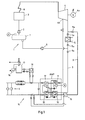
- Fig. 1 a device according to the invention for the recovery of heat of condensation from a thermodynamic cycle in the block diagram is shown.
- the steam power plant comprises as basic components a feedwater pump 2, a steam boiler 3, a steam turbine 4, in which the steam relaxes with release of energy is connected, connected to the turbine shaft generator 4a for generating electrical power and a condenser 5, in which the expanded steam is liquefied. Furthermore, the steam power plant also comprises a condensate pump 6, a feedwater tank 7 and a superheater 8 arranged behind the steam boiler for steam superheating.
- the steam power plant has a line bridge 9 in addition to the closed line cycle 1, with which the capacitor 5 is bridged.
- the evaporator 10 of an absorption heat pump AWP is integrated.
- the steam turbine 4 comprises a removal stage 4b, via which partially released steam can be withdrawn. This can then be introduced into the expeller 11 of the absorption heat pump AWP, where it can deliver the energy required for the expulsion to the working medium of the absorption heat pump.
- the partially expanded steam has a pressure of about 12 bar and a temperature of about 250 ° C at the removal stage 4b, wherein the steam temperature rapidly cools to a saturated steam temperature of about 188 ° C, which then at the entrance of the driver 11 for the there occurring process of expulsion is available.
- thermal oil from various production processes or hot water can also be used as the energy source for the expeller 11 of the absorption heat pump AWP.
- the output of the expeller 11 is connected to a not completely drawn for reasons of clarity condensate line A to the feedwater tank 7 of the steam power plant.
- the completely expanded steam is then divided behind the steam turbine 4 designed as a condensation turbine, wherein a portion of the steam is discharged from the line cycle 1 and introduced into the line bridge 9. There, the discharged part of the steam flows through the evaporator 10 of the absorption heat pump, where the steam condenses and flows as liquid condensate to the condensate pump 6.
- the respective proportion of the steam discharged into the line bridge 9 and the steam flowing through the condenser 5 can be adjusted precisely by corresponding valves 5a, 9a.
- the heat of the discharged part of the working medium of the steam power plant (water) is now transferred to another working medium, namely that of the absorption heat pump AWP.
- the working medium of the absorption heat pump AWP is preferably a water-lithium bromide solution.
- the transferred to the working medium of the absorption heat pump AWP heat is raised in this to a higher temperature level and then decoupled as useful heat in the absorber 13 and the condenser 12 of the absorption heat pump AWP in a Nutzadelniklauf 14.
- the lithium bromide solution diluted by the absorption of the water vapor is then conveyed by a liquid pump 13 'to the expeller 11, where it is re-evaporated by supplying the heat of the part-spun vapor discharged from the steam turbine 4 in the removal stage 4b. is concentrated.
- the water vapor formed in the expeller 11 by evaporating the lithium bromide solution is passed through a further steam line 11 'into the condenser 12. There it is condensed with heat to the heat transfer medium of the Nutz Son Vietnameselaufs 14 and flows as a liquefied working fluid via a water pipe 12 'back to the evaporator 10, where it is evaporated again.
- the evaporated lithium bromide solution is pumped back into the absorber 13 via the solution pump 11 ".
- This temperature is now the Nutzumblevorlauftemperatur and can, in contrast to the temperature of the discharged via the line bridge 9 steam of about 50 ° C - 70 ° C, preferably 60 ° C for a variety of internal or external applications can be used.
- the heat required for the useful heat circuit 14 may also be provided by a backup burner, such as a natural gas burner 16, which heats a hot water boiler 17, with the heat in the boiler 17 produced hot water is discharged via a further heat exchanger 18 to the heat transfer medium of the NutzSON Vietnamese Republiclaufs 14.
- the hot water boiler 17 can also be operated in addition to the absorption heat pump AWP, if particularly many consumers V are connected to the Nutznzonikank 14 (peak load) and at the same time retrieve its heat.
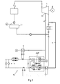
- FIG. 2 block diagram of a steam power plant with line bridge 9 and absorption heat pump AWP differs from that shown in Fig. 1 only in that instead of the hot water boiler 17, a further heat exchanger 19 is provided, via which the heat of the removal stage 4b from the Steam turbine 4 discharged partially expanded steam can be transmitted directly to the NutzSON Vietnamese Republiclauf 14, wherein the steam is condensed in the heat exchanger 19 and is returned via the return line A, not shown, directly into the feedwater tank 7.
- the additional use of the heat exchanger 19 may in turn be useful in the case of peak loads in the Nutzipponiklauf 14 and in the case of failure of the absorption heat pump AWP.
- the load point L1 relates to the operating state in which the generator 4a is operated with maximum electrical power, which corresponds to a tapping rate of 4.5 t / h.
- the Abdampfuza ancient Japanese Patent Application Laida 22.5 MW (load point L1) can be further used by increasing the temperature level in the absorption heat pump AWP, which does not take place at the expense of steam extraction and not at the expense of generator power.
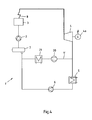
- the steam power plant again comprises a closed line cycle 1 'with a steam boiler 3, a superheater 8, a steam turbine 4 with a connected generator 4a and a condenser 5, a condensate pump 6, a feedwater tank 7 and a feedwater pump 2.
- the relaxed steam is divided behind the steam turbine 4, wherein a portion of the steam from the line cycle 1 'of the steam power plant shown in FIG. 4 and discharged into the line bridge 9' is initiated. There, this part will be in the compressor 20 again compacted.
- superheated steam is again generated at a pressure of about 1 bar and 192 ° C, which passes in the line bridge 9 'further into the condenser 21.
- the steam is liquefied and cooled, wherein the heat of condensation thereby released is coupled into a Nutztage Vietnamesemaschinemaschinemaschinemaschinemaschinemaschinemaschinemaschinemaschinemaschinemaschinemaschinen (not shown).
- the heat of condensation can be coupled at a high temperature level, so that in the Nutzgroniklauf the heat transfer medium is heated from 70 ° C to 90 ° C and with this high temperature for a Range of conceivable applications is available.
- the part not introduced into the pipe bridge 9 ' is liquefied in the condenser 5, giving off condensation heat at a low level.
- the water exiting from the condenser 5 is further conveyed in the condensate pump 6 and combines before entering the feedwater tank 7 with the water leaving the condenser 21 via the line bridge 9 '. With the entry into the feedwater tank 7, the cycle begins again.
Landscapes
- Engineering & Computer Science (AREA)
- Chemical & Material Sciences (AREA)
- Combustion & Propulsion (AREA)
- Mechanical Engineering (AREA)
- General Engineering & Computer Science (AREA)
- Physics & Mathematics (AREA)
- Thermal Sciences (AREA)
- Engine Equipment That Uses Special Cycles (AREA)
Priority Applications (1)
| Application Number | Priority Date | Filing Date | Title |
|---|---|---|---|
| PL07110440T PL1870646T3 (pl) | 2006-06-19 | 2007-06-18 | Sposób i urządzenie do odzyskiwania ciepła skraplania z obiegu termodynamicznego |
Applications Claiming Priority (2)
| Application Number | Priority Date | Filing Date | Title |
|---|---|---|---|
| DE102006028370 | 2006-06-19 | ||
| DE102006050706 | 2006-10-24 |
Publications (3)
| Publication Number | Publication Date |
|---|---|
| EP1870646A2 true EP1870646A2 (fr) | 2007-12-26 |
| EP1870646A3 EP1870646A3 (fr) | 2011-08-03 |
| EP1870646B1 EP1870646B1 (fr) | 2019-08-14 |
Family
ID=38519766
Family Applications (1)
| Application Number | Title | Priority Date | Filing Date |
|---|---|---|---|
| EP07110440.0A Active EP1870646B1 (fr) | 2006-06-19 | 2007-06-18 | Procédé et dispositif destinés à la récupération de chaleur de condensation à partir d'un cycle thermodynamique |
Country Status (3)
| Country | Link |
|---|---|
| EP (1) | EP1870646B1 (fr) |
| DK (1) | DK1870646T3 (fr) |
| PL (1) | PL1870646T3 (fr) |
Cited By (5)
| Publication number | Priority date | Publication date | Assignee | Title |
|---|---|---|---|---|
| FR2950958A1 (fr) * | 2009-10-02 | 2011-04-08 | Olivier Canavese | Procede d'optimisation de circuits vapeur grace a un circuit frigorifique |
| CN113375211A (zh) * | 2021-06-28 | 2021-09-10 | 大唐环境产业集团股份有限公司 | 燃煤机组供热系统、及运行方法 |
| CN114674585A (zh) * | 2022-03-23 | 2022-06-28 | 华电电力科学研究院有限公司 | 一种供热能力测量方法、装置及系统 |
| CN115059956A (zh) * | 2022-06-21 | 2022-09-16 | 西安热工研究院有限公司 | 火电机组深度余热利用耦合清洁能源热泵供热系统及运行方法 |
| CN115507566A (zh) * | 2022-09-28 | 2022-12-23 | 清华大学 | 一种供热制冰一体机及供热制冰方法 |
Families Citing this family (1)
| Publication number | Priority date | Publication date | Assignee | Title |
|---|---|---|---|---|
| CN106523050B (zh) * | 2016-12-16 | 2018-08-10 | 北京科技大学 | 复合动力循环系统及其运行方法及发电系统 |
Family Cites Families (4)
| Publication number | Priority date | Publication date | Assignee | Title |
|---|---|---|---|---|
| BE489030A (fr) * | ||||
| FI98858C (fi) * | 1994-01-24 | 1997-08-25 | Abb Installaatiot Oy | Menetelmä termisen energian jakelujärjestelmän yhteydessä ja termisen energian jakelujärjestelmä |
| DE19730353A1 (de) * | 1997-02-18 | 1998-08-20 | Feiler Christoph | Verfahren zum Betreiben einer Dampfkraftmaschinenanlage und Vorrichtungen zur Durchführung des Verfahrens |
| DE10214183C1 (de) * | 2002-03-28 | 2003-05-08 | Siemens Ag | Kraftwerk zur Kälteerzeugung |
-
2007
- 2007-06-18 PL PL07110440T patent/PL1870646T3/pl unknown
- 2007-06-18 EP EP07110440.0A patent/EP1870646B1/fr active Active
- 2007-06-18 DK DK07110440T patent/DK1870646T3/da active
Cited By (7)
| Publication number | Priority date | Publication date | Assignee | Title |
|---|---|---|---|---|
| FR2950958A1 (fr) * | 2009-10-02 | 2011-04-08 | Olivier Canavese | Procede d'optimisation de circuits vapeur grace a un circuit frigorifique |
| CN113375211A (zh) * | 2021-06-28 | 2021-09-10 | 大唐环境产业集团股份有限公司 | 燃煤机组供热系统、及运行方法 |
| CN114674585A (zh) * | 2022-03-23 | 2022-06-28 | 华电电力科学研究院有限公司 | 一种供热能力测量方法、装置及系统 |
| CN114674585B (zh) * | 2022-03-23 | 2024-01-12 | 华电电力科学研究院有限公司 | 一种供热能力测量方法、装置及系统 |
| CN115059956A (zh) * | 2022-06-21 | 2022-09-16 | 西安热工研究院有限公司 | 火电机组深度余热利用耦合清洁能源热泵供热系统及运行方法 |
| CN115507566A (zh) * | 2022-09-28 | 2022-12-23 | 清华大学 | 一种供热制冰一体机及供热制冰方法 |
| CN115507566B (zh) * | 2022-09-28 | 2024-02-23 | 清华大学 | 一种供热制冰一体机及供热制冰方法 |
Also Published As
| Publication number | Publication date |
|---|---|
| EP1870646A3 (fr) | 2011-08-03 |
| DK1870646T3 (da) | 2019-10-28 |
| PL1870646T3 (pl) | 2020-01-31 |
| EP1870646B1 (fr) | 2019-08-14 |
Similar Documents
| Publication | Publication Date | Title |
|---|---|---|
| EP3976940B1 (fr) | Système de conversion d'énergie thermique en énergie mécanique | |
| EP3362739B1 (fr) | Production de vapeur industrielle au moyen d'une pompe à chaleur haute température | |
| DE68926220T2 (de) | Verfahren und Vorrichtung zur Dampfkrafterzeugung | |
| DE102010042792A1 (de) | System zur Erzeugung mechanischer und/oder elektrischer Energie | |
| AT517535B1 (de) | Dampfkraftwerk | |
| EP2187051A1 (fr) | Procédé et dispositif destinés à la surchauffe intermédiaire dans une centrale thermique solaire à l'aide d'une évaporation indirecte | |
| EP1870646B1 (fr) | Procédé et dispositif destinés à la récupération de chaleur de condensation à partir d'un cycle thermodynamique | |
| CH705929A1 (de) | Verfahren zum Betreiben eines Kombikraftwerkes. | |
| DE112011100603T5 (de) | Abgaswärmerückgewinnungssystem, Energieversorgungssystem und Abgaswärmerückgewinnungsverfahren | |
| EP3080407A1 (fr) | Accumulation d'énergie au moyen d'un accumulateur de chaleur et d'un thermocompresseur de vapeur | |
| EP3559564A1 (fr) | Procédé et dispositif de production de froid de processus et de vapeur de processus | |
| DE102009026238A1 (de) | System und Verfahren zum Einsatz in einem Kombinationszyklus- oder Rankine-Zyklus-Kraftwerk unter Verwendung eines luftgekühlten Dampfkondensators | |
| DE102009026239A1 (de) | System und Verfahren zur Verwendung in einem Kombi- oder Rankine-Zyklus-Kraftwerk | |
| DE19943782C5 (de) | Gas- und Dampfturbinenanlage | |
| DE102013223661B4 (de) | Verfahren und Vorrichtung zur Energieumwandlung | |
| DE102012110579B4 (de) | Anlage und Verfahren zur Erzeugung von Prozessdampf | |
| WO2011045047A2 (fr) | Procédé à cycle (o)rc pour la transformation en énergie électrique de la chaleur produite lors de la combustion de biomasse et dispositif correspondant | |
| DE102004040730B3 (de) | Verfahren und Vorrichtung zum Nutzen von Abwärme | |
| DE102012100645B4 (de) | ORC - Organischer Rankine Zyklus | |
| EP3728800B1 (fr) | Centrale électrique | |
| WO2008031613A2 (fr) | Production d'électricité dans la plage de charge de base avec de l'énergie géothermique | |
| EP2559867A1 (fr) | Procédé de production d'énergie électrique à l'aide d'une centrale électrique combinée et centrale électrique combinée destinée à l'exécution du procédé | |
| DE102016217886A1 (de) | Anlage und Verfahren mit einer Wärmekraftanlage und einem Prozessverdichter | |
| EP2759680A1 (fr) | Centrale de turbine à gaz avec une flexibilité améliorée | |
| EP1270877B1 (fr) | Transformation de chaleur avec représsurisation |
Legal Events
| Date | Code | Title | Description |
|---|---|---|---|
| PUAI | Public reference made under article 153(3) epc to a published international application that has entered the european phase |
Free format text: ORIGINAL CODE: 0009012 |
|
| AK | Designated contracting states |
Kind code of ref document: A2 Designated state(s): AT BE BG CH CY CZ DE DK EE ES FI FR GB GR HU IE IS IT LI LT LU LV MC MT NL PL PT RO SE SI SK TR |
|
| AX | Request for extension of the european patent |
Extension state: AL BA HR MK YU |
|
| RAP1 | Party data changed (applicant data changed or rights of an application transferred) |
Owner name: FRITZ EGGER GMBH & CO. OG |
|
| PUAL | Search report despatched |
Free format text: ORIGINAL CODE: 0009013 |
|
| RIC1 | Information provided on ipc code assigned before grant |
Ipc: F25B 27/02 20060101AFI20070928BHEP Ipc: F01K 19/04 20060101ALI20110610BHEP |
|
| AK | Designated contracting states |
Kind code of ref document: A3 Designated state(s): AT BE BG CH CY CZ DE DK EE ES FI FR GB GR HU IE IS IT LI LT LU LV MC MT NL PL PT RO SE SI SK TR |
|
| AX | Request for extension of the european patent |
Extension state: AL BA HR MK RS |
|
| 17P | Request for examination filed |
Effective date: 20120124 |
|
| AKX | Designation fees paid |
Designated state(s): AT BE BG CH CY CZ DE DK EE ES FI FR GB GR HU IE IS IT LI LT LU LV MC MT NL PL PT RO SE SI SK TR |
|
| RAP1 | Party data changed (applicant data changed or rights of an application transferred) |
Owner name: FRITZ EGGER GMBH & CO. OG |
|
| STAA | Information on the status of an ep patent application or granted ep patent |
Free format text: STATUS: EXAMINATION IS IN PROGRESS |
|
| 17Q | First examination report despatched |
Effective date: 20170222 |
|
| GRAP | Despatch of communication of intention to grant a patent |
Free format text: ORIGINAL CODE: EPIDOSNIGR1 |
|
| STAA | Information on the status of an ep patent application or granted ep patent |
Free format text: STATUS: GRANT OF PATENT IS INTENDED |
|
| RIC1 | Information provided on ipc code assigned before grant |
Ipc: F25B 27/02 20060101AFI20181116BHEP Ipc: F01K 19/04 20060101ALI20181116BHEP Ipc: F01K 17/02 20060101ALI20181116BHEP |
|
| INTG | Intention to grant announced |
Effective date: 20181205 |
|
| GRAJ | Information related to disapproval of communication of intention to grant by the applicant or resumption of examination proceedings by the epo deleted |
Free format text: ORIGINAL CODE: EPIDOSDIGR1 |
|
| STAA | Information on the status of an ep patent application or granted ep patent |
Free format text: STATUS: EXAMINATION IS IN PROGRESS |
|
| GRAP | Despatch of communication of intention to grant a patent |
Free format text: ORIGINAL CODE: EPIDOSNIGR1 |
|
| STAA | Information on the status of an ep patent application or granted ep patent |
Free format text: STATUS: GRANT OF PATENT IS INTENDED |
|
| INTG | Intention to grant announced |
Effective date: 20190301 |
|
| GRAS | Grant fee paid |
Free format text: ORIGINAL CODE: EPIDOSNIGR3 |
|
| GRAA | (expected) grant |
Free format text: ORIGINAL CODE: 0009210 |
|
| STAA | Information on the status of an ep patent application or granted ep patent |
Free format text: STATUS: THE PATENT HAS BEEN GRANTED |
|
| AK | Designated contracting states |
Kind code of ref document: B1 Designated state(s): AT BE BG CH CY CZ DE DK EE ES FI FR GB GR HU IE IS IT LI LT LU LV MC MT NL PL PT RO SE SI SK TR |
|
| REG | Reference to a national code |
Ref country code: GB Ref legal event code: FG4D Free format text: NOT ENGLISH |
|
| REG | Reference to a national code |
Ref country code: CH Ref legal event code: EP Ref country code: AT Ref legal event code: REF Ref document number: 1167505 Country of ref document: AT Kind code of ref document: T Effective date: 20190815 |
|
| REG | Reference to a national code |
Ref country code: IE Ref legal event code: FG4D Free format text: LANGUAGE OF EP DOCUMENT: GERMAN |
|
| REG | Reference to a national code |
Ref country code: DE Ref legal event code: R096 Ref document number: 502007016747 Country of ref document: DE |
|
| REG | Reference to a national code |
Ref country code: DK Ref legal event code: T3 Effective date: 20191025 |
|
| REG | Reference to a national code |
Ref country code: RO Ref legal event code: EPE |
|
| REG | Reference to a national code |
Ref country code: SE Ref legal event code: TRGR |
|
| REG | Reference to a national code |
Ref country code: CH Ref legal event code: NV Representative=s name: SCHMAUDER AND PARTNER AG PATENT- UND MARKENANW, CH |
|
| REG | Reference to a national code |
Ref country code: NL Ref legal event code: MP Effective date: 20190814 |
|
| REG | Reference to a national code |
Ref country code: LT Ref legal event code: MG4D |
|
| PG25 | Lapsed in a contracting state [announced via postgrant information from national office to epo] |
Ref country code: BG Free format text: LAPSE BECAUSE OF FAILURE TO SUBMIT A TRANSLATION OF THE DESCRIPTION OR TO PAY THE FEE WITHIN THE PRESCRIBED TIME-LIMIT Effective date: 20191114 Ref country code: NL Free format text: LAPSE BECAUSE OF FAILURE TO SUBMIT A TRANSLATION OF THE DESCRIPTION OR TO PAY THE FEE WITHIN THE PRESCRIBED TIME-LIMIT Effective date: 20190814 Ref country code: LT Free format text: LAPSE BECAUSE OF FAILURE TO SUBMIT A TRANSLATION OF THE DESCRIPTION OR TO PAY THE FEE WITHIN THE PRESCRIBED TIME-LIMIT Effective date: 20190814 Ref country code: PT Free format text: LAPSE BECAUSE OF FAILURE TO SUBMIT A TRANSLATION OF THE DESCRIPTION OR TO PAY THE FEE WITHIN THE PRESCRIBED TIME-LIMIT Effective date: 20191216 |
|
| PG25 | Lapsed in a contracting state [announced via postgrant information from national office to epo] |
Ref country code: GR Free format text: LAPSE BECAUSE OF FAILURE TO SUBMIT A TRANSLATION OF THE DESCRIPTION OR TO PAY THE FEE WITHIN THE PRESCRIBED TIME-LIMIT Effective date: 20191115 Ref country code: LV Free format text: LAPSE BECAUSE OF FAILURE TO SUBMIT A TRANSLATION OF THE DESCRIPTION OR TO PAY THE FEE WITHIN THE PRESCRIBED TIME-LIMIT Effective date: 20190814 Ref country code: ES Free format text: LAPSE BECAUSE OF FAILURE TO SUBMIT A TRANSLATION OF THE DESCRIPTION OR TO PAY THE FEE WITHIN THE PRESCRIBED TIME-LIMIT Effective date: 20190814 Ref country code: IS Free format text: LAPSE BECAUSE OF FAILURE TO SUBMIT A TRANSLATION OF THE DESCRIPTION OR TO PAY THE FEE WITHIN THE PRESCRIBED TIME-LIMIT Effective date: 20191214 |
|
| PG25 | Lapsed in a contracting state [announced via postgrant information from national office to epo] |
Ref country code: TR Free format text: LAPSE BECAUSE OF FAILURE TO SUBMIT A TRANSLATION OF THE DESCRIPTION OR TO PAY THE FEE WITHIN THE PRESCRIBED TIME-LIMIT Effective date: 20190814 |
|
| PG25 | Lapsed in a contracting state [announced via postgrant information from national office to epo] |
Ref country code: EE Free format text: LAPSE BECAUSE OF FAILURE TO SUBMIT A TRANSLATION OF THE DESCRIPTION OR TO PAY THE FEE WITHIN THE PRESCRIBED TIME-LIMIT Effective date: 20190814 |
|
| PG25 | Lapsed in a contracting state [announced via postgrant information from national office to epo] |
Ref country code: IS Free format text: LAPSE BECAUSE OF FAILURE TO SUBMIT A TRANSLATION OF THE DESCRIPTION OR TO PAY THE FEE WITHIN THE PRESCRIBED TIME-LIMIT Effective date: 20200224 Ref country code: CZ Free format text: LAPSE BECAUSE OF FAILURE TO SUBMIT A TRANSLATION OF THE DESCRIPTION OR TO PAY THE FEE WITHIN THE PRESCRIBED TIME-LIMIT Effective date: 20190814 Ref country code: SK Free format text: LAPSE BECAUSE OF FAILURE TO SUBMIT A TRANSLATION OF THE DESCRIPTION OR TO PAY THE FEE WITHIN THE PRESCRIBED TIME-LIMIT Effective date: 20190814 |
|
| REG | Reference to a national code |
Ref country code: DE Ref legal event code: R097 Ref document number: 502007016747 Country of ref document: DE |
|
| PLBE | No opposition filed within time limit |
Free format text: ORIGINAL CODE: 0009261 |
|
| STAA | Information on the status of an ep patent application or granted ep patent |
Free format text: STATUS: NO OPPOSITION FILED WITHIN TIME LIMIT |
|
| PG2D | Information on lapse in contracting state deleted |
Ref country code: IS |
|
| 26N | No opposition filed |
Effective date: 20200603 |
|
| PG25 | Lapsed in a contracting state [announced via postgrant information from national office to epo] |
Ref country code: SI Free format text: LAPSE BECAUSE OF FAILURE TO SUBMIT A TRANSLATION OF THE DESCRIPTION OR TO PAY THE FEE WITHIN THE PRESCRIBED TIME-LIMIT Effective date: 20190814 |
|
| PG25 | Lapsed in a contracting state [announced via postgrant information from national office to epo] |
Ref country code: MC Free format text: LAPSE BECAUSE OF FAILURE TO SUBMIT A TRANSLATION OF THE DESCRIPTION OR TO PAY THE FEE WITHIN THE PRESCRIBED TIME-LIMIT Effective date: 20190814 |
|
| PG25 | Lapsed in a contracting state [announced via postgrant information from national office to epo] |
Ref country code: LU Free format text: LAPSE BECAUSE OF NON-PAYMENT OF DUE FEES Effective date: 20200618 |
|
| REG | Reference to a national code |
Ref country code: BE Ref legal event code: MM Effective date: 20200630 |
|
| PG25 | Lapsed in a contracting state [announced via postgrant information from national office to epo] |
Ref country code: IE Free format text: LAPSE BECAUSE OF NON-PAYMENT OF DUE FEES Effective date: 20200618 |
|
| PG25 | Lapsed in a contracting state [announced via postgrant information from national office to epo] |
Ref country code: BE Free format text: LAPSE BECAUSE OF NON-PAYMENT OF DUE FEES Effective date: 20200630 |
|
| PG25 | Lapsed in a contracting state [announced via postgrant information from national office to epo] |
Ref country code: MT Free format text: LAPSE BECAUSE OF FAILURE TO SUBMIT A TRANSLATION OF THE DESCRIPTION OR TO PAY THE FEE WITHIN THE PRESCRIBED TIME-LIMIT Effective date: 20190814 Ref country code: CY Free format text: LAPSE BECAUSE OF FAILURE TO SUBMIT A TRANSLATION OF THE DESCRIPTION OR TO PAY THE FEE WITHIN THE PRESCRIBED TIME-LIMIT Effective date: 20190814 |
|
| P01 | Opt-out of the competence of the unified patent court (upc) registered |
Effective date: 20230517 |
|
| PGFP | Annual fee paid to national office [announced via postgrant information from national office to epo] |
Ref country code: FI Payment date: 20250624 Year of fee payment: 19 |
|
| PGFP | Annual fee paid to national office [announced via postgrant information from national office to epo] |
Ref country code: PL Payment date: 20250605 Year of fee payment: 19 Ref country code: DE Payment date: 20250624 Year of fee payment: 19 |
|
| PGFP | Annual fee paid to national office [announced via postgrant information from national office to epo] |
Ref country code: GB Payment date: 20250624 Year of fee payment: 19 Ref country code: DK Payment date: 20250627 Year of fee payment: 19 |
|
| PGFP | Annual fee paid to national office [announced via postgrant information from national office to epo] |
Ref country code: FR Payment date: 20250625 Year of fee payment: 19 |
|
| PGFP | Annual fee paid to national office [announced via postgrant information from national office to epo] |
Ref country code: RO Payment date: 20250618 Year of fee payment: 19 Ref country code: AT Payment date: 20250626 Year of fee payment: 19 |
|
| PGFP | Annual fee paid to national office [announced via postgrant information from national office to epo] |
Ref country code: SE Payment date: 20250625 Year of fee payment: 19 |
|
| PGFP | Annual fee paid to national office [announced via postgrant information from national office to epo] |
Ref country code: IT Payment date: 20250626 Year of fee payment: 19 |
|
| PGFP | Annual fee paid to national office [announced via postgrant information from national office to epo] |
Ref country code: CH Payment date: 20250701 Year of fee payment: 19 |