EP1870655A2 - Unité de transmission de la chaleur pour un moteur à combustion interne - Google Patents
Unité de transmission de la chaleur pour un moteur à combustion interne Download PDFInfo
- Publication number
- EP1870655A2 EP1870655A2 EP07105456A EP07105456A EP1870655A2 EP 1870655 A2 EP1870655 A2 EP 1870655A2 EP 07105456 A EP07105456 A EP 07105456A EP 07105456 A EP07105456 A EP 07105456A EP 1870655 A2 EP1870655 A2 EP 1870655A2
- Authority
- EP
- European Patent Office
- Prior art keywords
- gas
- heat transfer
- cooled
- channel
- transfer unit
- Prior art date
- Legal status (The legal status is an assumption and is not a legal conclusion. Google has not performed a legal analysis and makes no representation as to the accuracy of the status listed.)
- Withdrawn
Links
Images
Classifications
-
- F—MECHANICAL ENGINEERING; LIGHTING; HEATING; WEAPONS; BLASTING
- F28—HEAT EXCHANGE IN GENERAL
- F28D—HEAT-EXCHANGE APPARATUS, NOT PROVIDED FOR IN ANOTHER SUBCLASS, IN WHICH THE HEAT-EXCHANGE MEDIA DO NOT COME INTO DIRECT CONTACT
- F28D7/00—Heat-exchange apparatus having stationary tubular conduit assemblies for both heat-exchange media, the media being in contact with different sides of a conduit wall
- F28D7/10—Heat-exchange apparatus having stationary tubular conduit assemblies for both heat-exchange media, the media being in contact with different sides of a conduit wall the conduits being arranged one within the other, e.g. concentrically
- F28D7/12—Heat-exchange apparatus having stationary tubular conduit assemblies for both heat-exchange media, the media being in contact with different sides of a conduit wall the conduits being arranged one within the other, e.g. concentrically the surrounding tube being closed at one end, e.g. return type
-
- F—MECHANICAL ENGINEERING; LIGHTING; HEATING; WEAPONS; BLASTING
- F01—MACHINES OR ENGINES IN GENERAL; ENGINE PLANTS IN GENERAL; STEAM ENGINES
- F01N—GAS-FLOW SILENCERS OR EXHAUST APPARATUS FOR MACHINES OR ENGINES IN GENERAL; GAS-FLOW SILENCERS OR EXHAUST APPARATUS FOR INTERNAL-COMBUSTION ENGINES
- F01N3/00—Exhaust or silencing apparatus having means for purifying, rendering innocuous, or otherwise treating exhaust
- F01N3/02—Exhaust or silencing apparatus having means for purifying, rendering innocuous, or otherwise treating exhaust for cooling, or for removing solid constituents of, exhaust
-
- F—MECHANICAL ENGINEERING; LIGHTING; HEATING; WEAPONS; BLASTING
- F28—HEAT EXCHANGE IN GENERAL
- F28F—DETAILS OF HEAT-EXCHANGE AND HEAT-TRANSFER APPARATUS, OF GENERAL APPLICATION
- F28F13/00—Arrangements for modifying heat-transfer, e.g. increasing, decreasing
- F28F13/06—Arrangements for modifying heat-transfer, e.g. increasing, decreasing by affecting the pattern of flow of the heat-exchange media
- F28F13/08—Arrangements for modifying heat-transfer, e.g. increasing, decreasing by affecting the pattern of flow of the heat-exchange media by varying the cross-section of the flow channels
-
- F—MECHANICAL ENGINEERING; LIGHTING; HEATING; WEAPONS; BLASTING
- F28—HEAT EXCHANGE IN GENERAL
- F28D—HEAT-EXCHANGE APPARATUS, NOT PROVIDED FOR IN ANOTHER SUBCLASS, IN WHICH THE HEAT-EXCHANGE MEDIA DO NOT COME INTO DIRECT CONTACT
- F28D21/00—Heat-exchange apparatus not covered by any of the groups F28D1/00 - F28D20/00
- F28D21/0001—Recuperative heat exchangers
- F28D21/0003—Recuperative heat exchangers the heat being recuperated from exhaust gases
-
- F—MECHANICAL ENGINEERING; LIGHTING; HEATING; WEAPONS; BLASTING
- F28—HEAT EXCHANGE IN GENERAL
- F28F—DETAILS OF HEAT-EXCHANGE AND HEAT-TRANSFER APPARATUS, OF GENERAL APPLICATION
- F28F2255/00—Heat exchanger elements made of materials having special features or resulting from particular manufacturing processes
- F28F2255/14—Heat exchanger elements made of materials having special features or resulting from particular manufacturing processes molded
-
- Y—GENERAL TAGGING OF NEW TECHNOLOGICAL DEVELOPMENTS; GENERAL TAGGING OF CROSS-SECTIONAL TECHNOLOGIES SPANNING OVER SEVERAL SECTIONS OF THE IPC; TECHNICAL SUBJECTS COVERED BY FORMER USPC CROSS-REFERENCE ART COLLECTIONS [XRACs] AND DIGESTS
- Y02—TECHNOLOGIES OR APPLICATIONS FOR MITIGATION OR ADAPTATION AGAINST CLIMATE CHANGE
- Y02T—CLIMATE CHANGE MITIGATION TECHNOLOGIES RELATED TO TRANSPORTATION
- Y02T10/00—Road transport of goods or passengers
- Y02T10/10—Internal combustion engine [ICE] based vehicles
- Y02T10/12—Improving ICE efficiencies
Definitions
- the invention relates to a heat transfer unit for an internal combustion engine, in particular for cooling exhaust gases, comprising a housing in which a channel through which a gas to be cooled flows and a channel through which a cooling fluid flows are separated from one another by one or more partitions a first inlet and a first outlet for the gas to be cooled as well as a second inlet and a second outlet for the cooling fluid are formed on the housing.
- Heat transfer units for internal combustion engines are well known and are described in a variety of applications. They serve, for example, for cooling the charge air of an internal combustion engine or for cooling oil or exhaust gas. Thus, various types of such heat transfer units have been described. To mention here are, for example, plate heat exchanger or tube bundle heat exchanger.
- the cooling fluid used in this case is usually the cooling fluid of the internal combustion engine. Lately, in particular for exhaust gas cooling and multi-part heat transfer units made of die-cast aluminum were known, whereby the exhaust gas coolers are very simple and inexpensive to produce in their construction.
- U1 describes a U-shaped flow-through exhaust heat exchanger made of die-cast aluminum, which has a coolant flowing through the jacket for cooling the exhaust gases.
- the flow around the coolant jacket exhaust passage is flowed through in a U-shape, that is, that inlet and outlet at the same Front side of the radiator are located.
- a partition wall is arranged for this purpose.
- the flow-through cross-section of the flowed through by the gas to be cooled channel in the region of the first inlet is greater than in the region of the first outlet.
- the heat transfer deteriorates or the inlet cross-section is so small that an extremely high pressure loss occurs.
- the claimed heat exchanger has a higher flow velocity in the area of the outlet than in known heat exchangers, which leads to improved heat transfer in the outlet area. This higher velocity also reduces the thickness of the insulating boundary layer, which also improves the heat transfer.
- the pressure loss in the entrance area is reduced.
- the flow-through cross-section of the channel through which the gas to be cooled changes in the main flow direction from the first inlet to the first Outlet by contouring limiting side walls in sections.
- the definition of the optimum cross-section can for example take place by experiments in which the heat transfer for each section is calculated and measured under existing conditions.
- the flow-through cross-section of the channel through which the gas to be cooled reduces in the main flow direction such that a substantially constant flow velocity of the gas to be cooled is established.
- an optimization takes place between the pressure loss increasing with increasing speed and the improvement of the cooling capacity with increasing flow velocity, whereby the highest flow velocity at the inlet and thus the highest occurring pressure loss can be reduced with the same size.
- the pressure loss thus increases only in the main flow direction as the density of the gas decreases and the loss coefficient changes due to changing geometry. However, it is independent of the quadratic effect on the pressure loss flow velocity.
- the distance between the limiting sidewalls of the channel through which the gas to be cooled decreases decreases in the main flow direction. It is thus maintained an easy to manufacture design and the goal of increasing the cooling performance with optimized pressure loss achieved in a simple manner.
- the distance between ribs protruding into the channel through which the gas to be cooled decreases in the main flow direction decreases.
- the ribs can be arranged such that the cross-section additionally narrows or else the entire cross-sectional constriction is produced by the ribs. In both cases, with optimized pressure loss, a cooling performance increase is achieved in comparison to known designs.
- the reduction in the distance between the ribs is achieved by broadening the ribs in the main flow direction.
- the necessary width for constant maintenance of the flow rate is calculated in a relatively simple manner by appropriate calculation and to be transferred to appropriate molds for die casting.
- the reduction in the distance between the ribs is done by increasing the number of ribs in the main flow direction.
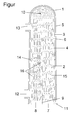
- the figure shows a plan view of a heat transfer unit according to the invention in a sectional view.
- the heat transfer unit shown in the figure which is used in particular for cooling exhaust gases of an internal combustion engine, consists of a housing 1, in which a channel 2 through which a gas to be cooled and a channel 3 through which a cooling fluid flows are arranged.
- the housing 1 consists of a single or multi-part inner shell 4, as well as an outer shell 5 surrounding the inner shell 4, which is arranged substantially at a distance from the inner shell 4.
- the flowed through by the cooling fluid channel 3 is arranged in the present embodiment between the inner shell 4 and the outer shell 5, while the flow-through of the gas to be cooled channel 2 is limited by the inner shell 4.
- the inner shell 4 forms a partition wall 6 between the two fluids in heat exchange.
- the inner shell 4 is designed to be open on one side and has on its open end side a first inlet 7 and a first outlet 8 arranged next to it, which are separated from one another by a middle wall 9 which extends from the first inlet 7 to a reversal region 10 of the heat transfer unit ,
- the center wall 9 terminates at a distance to the inlet 7 and the outlet 8 opposite end face of the heat transfer unit, which in approximately corresponds to the distance between the middle wall 9 and the partition wall 6 at the inlet 7 and at the outlet 8. Accordingly, the gas flowing in the channel 2 is deflected in this area in a U-shaped manner and flows from the inlet 7 via the reversal area 10 to the outlet 8 arranged next to the inlet 7.
- the inner shell 4 additionally has a flange-shaped enlargement 11, via which the outer shell 5 can be fastened to the inner shell 4, for example by friction stir welding. At the same time, this flange-shaped enlargement serves to close the channel 3 through which the cooling fluid flows.
- the outer shell 5 has a second inlet 12 and a second outlet 13, which are arranged in the present embodiment in the region of the end faces of the heat transfer unit, but laterally on the outer shell.
- webs 14 are additionally arranged, which provide a positive guidance of the cooling fluid, so that the cooling fluid can not flow directly from the inlet 12 to the outlet 13, but it is ensured that the entire flowed through by the cooling fluid channel 3 continuously with new coolant is supplied and dead water areas are avoided.
- Such positive guidance by the webs 14 can be carried out, for example, helically or meandering.
- ribs 15 protrude into the channel 2 to be cooled by the gas to be cooled, whereby the heat transfer between the two fluids is significantly improved and at the same time with appropriate design and by the use of the heat transfer unit as exhaust gas cooler sooting or sooting can be avoided can.
- These ribs 15 are also continued in the form of protrusions 16 on the middle wall 9 and the partitions 6, so that even when offset in rows one behind the other ribs, the flow-through cross sections in the range of a row of ribs can be kept largely constant without having to change the rib shape ,
- the partition wall 6 and the middle wall 9 thus form the gas flow-through channel 2 limiting side walls, which are according to the invention arranged to each other so that the effetströmbare cross-section between the side walls 6, 9th reduced from the inlet 7 to the outlet 8.
- this cross-sectional constriction is achieved in that the middle wall 9 in the region of the inlet 7 has a greater distance to the partition wall 6 than in the region of the outlet 8.
- the middle wall 9 is thus slightly obliquely in relation to the partitions 6 over its entire length arranged the heat transfer unit or arranged employed at a small angle to the partitions.
- the number of existing ribs 15 in the channel remains approximately the same in each section, so that in the present embodiment, five ribs are arranged in each cross-section, it being noted that the ribs 15 in the region of the inlet 7 through The larger available cross-section significantly greater distance from each other than the ribs 15 in the region of the outlet eighth
- the inclination of the center wall 9 is carried out to maintain a constant flow velocity or optimized for the local temperature range flow velocity in the heat transfer unit or in the flow of the gas to be cooled channel. 2
- the cross section in this region is widened, so that the flow velocity and thus the pressure loss increasing quadratically to the flow velocity are reduced. Viewed over the entire flow path can thereby be achieved a reduction of the total pressure loss. Due to the oblique arrangement of the middle wall 9 or by providing a larger number of ribs 15 to the outlet 8 out now, the flow rate is kept constant by the cross section is reduced according to the continuity equation with decreasing temperature and thus according to ideal gas law of increasing density. There is thus a linear dependence between the density and the selected cross-section.
- the heat transfer is influenced by the thickness of the local boundary layer and there is a strong influence over the local temperature gradient between the gas to be cooled and the cooling fluid. Therefore, especially with small occurring temperature gradients, as they occur in particular in the region of the outlet in customarily constructed heat exchanger units, the heat transfer drops significantly.
- the advantages for the heat exchanger unit according to the invention are that the local flow velocity in the region of the outlet 8 is increased by the smaller cross section, whereby heat transfer and cooling performance are improved. This higher velocity also reduces the thickness of the insulating boundary layer, which also improves the heat transfer.
- the invention is not limited to the above-described embodiment, but changes in the design of the heat transfer unit, for example with respect to the arrangements of the cooling fluid flow channel 3 or the production of the heat transfer unit, are conceivable.
- the cooling fluid flowed through channel 3 could be surrounded by the gas channel leading 2 or the heat exchanger may be designed as a plate or tube bundle heat exchanger.
- a through-flow from one end face to the opposite end heat exchanger without deflection is executable, so that the arrangement of the inlets and outlets is largely freely selectable.
Landscapes
- Engineering & Computer Science (AREA)
- Mechanical Engineering (AREA)
- General Engineering & Computer Science (AREA)
- Physics & Mathematics (AREA)
- Thermal Sciences (AREA)
- Chemical & Material Sciences (AREA)
- Combustion & Propulsion (AREA)
- Heat-Exchange Devices With Radiators And Conduit Assemblies (AREA)
- Exhaust Gas After Treatment (AREA)
Applications Claiming Priority (1)
| Application Number | Priority Date | Filing Date | Title |
|---|---|---|---|
| DE200610029043 DE102006029043B4 (de) | 2006-06-24 | 2006-06-24 | Wärmeübertragungseinheit für eine Verbrennungskraftmaschine |
Publications (2)
| Publication Number | Publication Date |
|---|---|
| EP1870655A2 true EP1870655A2 (fr) | 2007-12-26 |
| EP1870655A3 EP1870655A3 (fr) | 2011-01-19 |
Family
ID=38542022
Family Applications (1)
| Application Number | Title | Priority Date | Filing Date |
|---|---|---|---|
| EP07105456A Withdrawn EP1870655A3 (fr) | 2006-06-24 | 2007-04-02 | Unité de transmission de la chaleur pour un moteur à combustion interne |
Country Status (2)
| Country | Link |
|---|---|
| EP (1) | EP1870655A3 (fr) |
| DE (1) | DE102006029043B4 (fr) |
Cited By (4)
| Publication number | Priority date | Publication date | Assignee | Title |
|---|---|---|---|---|
| EP2031336A3 (fr) * | 2007-08-31 | 2011-05-18 | Pierburg GmbH | Echangeur de chaleur pour un moteur à combustion interne |
| CN102112843B (zh) * | 2008-08-02 | 2012-11-28 | 皮尔伯格有限责任公司 | 用于内燃机的传热单元 |
| CN108627044A (zh) * | 2018-07-04 | 2018-10-09 | 西安热工研究院有限公司 | 一种用于超临界二氧化碳回热器变截面机翼型高效换热通道设计方法 |
| CN115360153A (zh) * | 2022-08-24 | 2022-11-18 | 南京中电芯谷高频器件产业技术研究院有限公司 | 一种高集成大功率微波源制冷基板及其制备方法 |
Families Citing this family (2)
| Publication number | Priority date | Publication date | Assignee | Title |
|---|---|---|---|---|
| DE102011081031A1 (de) * | 2011-08-16 | 2013-02-21 | Behr Gmbh & Co. Kg | Abgaswärmeübertrager |
| DE102011053421A1 (de) * | 2011-09-09 | 2013-03-14 | Pierburg Gmbh | Vorprodukt eines Gehäuseteils, Innengehäuse, Wärmeübertragungsvorrichtung und Verfahren zur Herstellung eines derartigen Innengehäuses und einer derartigen Wärmeübertragungsvorrichtung |
Citations (3)
| Publication number | Priority date | Publication date | Assignee | Title |
|---|---|---|---|---|
| JP2001027157A (ja) | 1999-07-13 | 2001-01-30 | Mitsubishi Motors Corp | Egrクーラの構造 |
| DE202004003131U1 (de) | 2004-03-01 | 2004-05-19 | Albert Handtmann Metallgusswerk Gmbh & Co. Kg | Mehrteiliger Abgaswärmetauscher aus Aluminiumdruckguß |
| DE10321533A1 (de) | 2003-05-14 | 2004-12-09 | Pierburg Gmbh | Luftansaugkanalsystem für eine Verbrennungskraftmaschine |
Family Cites Families (6)
| Publication number | Priority date | Publication date | Assignee | Title |
|---|---|---|---|---|
| BE416338A (fr) * | 1924-06-07 | |||
| JPS60141541A (ja) * | 1983-12-29 | 1985-07-26 | Nippon Soken Inc | ブロツク型熱交換エレメントの製造方法 |
| US5172759A (en) * | 1989-10-31 | 1992-12-22 | Nippondenso Co., Ltd. | Plate-type refrigerant evaporator |
| JP2003004389A (ja) * | 2001-06-25 | 2003-01-08 | Nissan Motor Co Ltd | Egrガス冷却装置 |
| US7108054B2 (en) * | 2003-09-11 | 2006-09-19 | Honeywell International, Inc. | Heat exchanger |
| US7073573B2 (en) * | 2004-06-09 | 2006-07-11 | Honeywell International, Inc. | Decreased hot side fin density heat exchanger |
-
2006
- 2006-06-24 DE DE200610029043 patent/DE102006029043B4/de active Active
-
2007
- 2007-04-02 EP EP07105456A patent/EP1870655A3/fr not_active Withdrawn
Patent Citations (3)
| Publication number | Priority date | Publication date | Assignee | Title |
|---|---|---|---|---|
| JP2001027157A (ja) | 1999-07-13 | 2001-01-30 | Mitsubishi Motors Corp | Egrクーラの構造 |
| DE10321533A1 (de) | 2003-05-14 | 2004-12-09 | Pierburg Gmbh | Luftansaugkanalsystem für eine Verbrennungskraftmaschine |
| DE202004003131U1 (de) | 2004-03-01 | 2004-05-19 | Albert Handtmann Metallgusswerk Gmbh & Co. Kg | Mehrteiliger Abgaswärmetauscher aus Aluminiumdruckguß |
Cited By (5)
| Publication number | Priority date | Publication date | Assignee | Title |
|---|---|---|---|---|
| EP2031336A3 (fr) * | 2007-08-31 | 2011-05-18 | Pierburg GmbH | Echangeur de chaleur pour un moteur à combustion interne |
| CN102112843B (zh) * | 2008-08-02 | 2012-11-28 | 皮尔伯格有限责任公司 | 用于内燃机的传热单元 |
| CN108627044A (zh) * | 2018-07-04 | 2018-10-09 | 西安热工研究院有限公司 | 一种用于超临界二氧化碳回热器变截面机翼型高效换热通道设计方法 |
| CN115360153A (zh) * | 2022-08-24 | 2022-11-18 | 南京中电芯谷高频器件产业技术研究院有限公司 | 一种高集成大功率微波源制冷基板及其制备方法 |
| CN115360153B (zh) * | 2022-08-24 | 2023-09-29 | 南京中电芯谷高频器件产业技术研究院有限公司 | 一种微波源制冷基板及其制备方法 |
Also Published As
| Publication number | Publication date |
|---|---|
| DE102006029043A1 (de) | 2007-12-27 |
| EP1870655A3 (fr) | 2011-01-19 |
| DE102006029043B4 (de) | 2015-04-23 |
Similar Documents
| Publication | Publication Date | Title |
|---|---|---|
| DE102008036222B3 (de) | Wärmeübertragungseinheit für eine Verbrennungskraftmaschine | |
| EP1999423B1 (fr) | Refroidisseur de gaz d'echappement pour véhicule automobile | |
| DE69216389T2 (de) | Versetzt angeordnete streifenförmige rippe für einen kompakten wärmetauscher | |
| EP1996888B1 (fr) | Échangeur thermique pour véhicule automobile | |
| EP1955001A1 (fr) | Dispositif de refroidissement pour moteur a combustion interne | |
| DE202006009464U1 (de) | Wärmetauscher | |
| EP1559980A1 (fr) | Echangeur de chaleur à plaques | |
| DE102009047620C5 (de) | Wärmeübertrager mit Rohrbündel | |
| DE112013007041B4 (de) | Wärmetauscher | |
| EP3265738B1 (fr) | Échangeur de chaleur, en particulier pour véhicule automobile | |
| EP1870655A2 (fr) | Unité de transmission de la chaleur pour un moteur à combustion interne | |
| EP2037201A2 (fr) | Module d'air de suralimentation pour un moteur à combustion interne | |
| EP0286704B1 (fr) | Echangeur de chaleur pour deux milieux fluides | |
| DE202004011489U1 (de) | Wärmeaustauscher für Hochtemperatur-Anwendungen, insbesondere Ladeluftkühler | |
| DE102007019206B4 (de) | Wärmeübertragungsvorrichtung | |
| DE102020103714A1 (de) | Wärmetauscher | |
| WO2012159806A1 (fr) | Dispositif de transfert de chaleur | |
| DE3148941A1 (de) | Oelkuehler in scheibenbauweise | |
| DE3408624A1 (de) | Luftgekuehlte hubkolbenbrennkraftmaschine | |
| EP2031336B1 (fr) | Echangeur de chaleur pour un moteur à combustion interne | |
| EP3203173A1 (fr) | Échangeur thermique de gaz d'échappement | |
| DE102006061440A1 (de) | Kühlflüssigkeitskühler | |
| DE102007008865B3 (de) | Wärmeübertragungsvorrichtung | |
| DE102012111928A1 (de) | Wärmetauscher für eine Verbrennungskraftmaschine | |
| EP3161402B1 (fr) | Échangeur thermique |
Legal Events
| Date | Code | Title | Description |
|---|---|---|---|
| PUAI | Public reference made under article 153(3) epc to a published international application that has entered the european phase |
Free format text: ORIGINAL CODE: 0009012 |
|
| 17P | Request for examination filed |
Effective date: 20070402 |
|
| AK | Designated contracting states |
Kind code of ref document: A2 Designated state(s): AT BE BG CH CY CZ DE DK EE ES FI FR GB GR HU IE IS IT LI LT LU LV MC MT NL PL PT RO SE SI SK TR |
|
| AX | Request for extension of the european patent |
Extension state: AL BA HR MK YU |
|
| PUAL | Search report despatched |
Free format text: ORIGINAL CODE: 0009013 |
|
| AK | Designated contracting states |
Kind code of ref document: A3 Designated state(s): AT BE BG CH CY CZ DE DK EE ES FI FR GB GR HU IE IS IT LI LT LU LV MC MT NL PL PT RO SE SI SK TR |
|
| AX | Request for extension of the european patent |
Extension state: AL BA HR MK RS |
|
| AKX | Designation fees paid |
Designated state(s): AT BE BG CH CY CZ DE DK EE ES FI FR GB GR HU IE IS IT LI LT LU LV MC MT NL PL PT RO SE SI SK TR |
|
| STAA | Information on the status of an ep patent application or granted ep patent |
Free format text: STATUS: THE APPLICATION IS DEEMED TO BE WITHDRAWN |
|
| 18D | Application deemed to be withdrawn |
Effective date: 20141101 |