EP1870667A2 - Dispositifs et procédés destinés à la détection de surfaces et à la production de pièces prothèses dentaires - Google Patents
Dispositifs et procédés destinés à la détection de surfaces et à la production de pièces prothèses dentaires Download PDFInfo
- Publication number
- EP1870667A2 EP1870667A2 EP07015279A EP07015279A EP1870667A2 EP 1870667 A2 EP1870667 A2 EP 1870667A2 EP 07015279 A EP07015279 A EP 07015279A EP 07015279 A EP07015279 A EP 07015279A EP 1870667 A2 EP1870667 A2 EP 1870667A2
- Authority
- EP
- European Patent Office
- Prior art keywords
- data
- devices
- dental prosthesis
- surface detection
- tooth
- Prior art date
- Legal status (The legal status is an assumption and is not a legal conclusion. Google has not performed a legal analysis and makes no representation as to the accuracy of the status listed.)
- Withdrawn
Links
- 238000000034 method Methods 0.000 title claims abstract description 76
- 238000001514 detection method Methods 0.000 claims abstract description 67
- 238000004519 manufacturing process Methods 0.000 claims abstract description 61
- 239000007943 implant Substances 0.000 claims abstract description 20
- 238000005259 measurement Methods 0.000 claims description 45
- 238000003780 insertion Methods 0.000 claims description 36
- 230000037431 insertion Effects 0.000 claims description 36
- 238000013461 design Methods 0.000 claims description 22
- 238000002360 preparation method Methods 0.000 claims description 15
- 238000012545 processing Methods 0.000 claims description 8
- 230000005540 biological transmission Effects 0.000 claims description 6
- 238000010276 construction Methods 0.000 claims description 5
- 210000001847 jaw Anatomy 0.000 description 37
- 238000005516 engineering process Methods 0.000 description 22
- 230000008901 benefit Effects 0.000 description 13
- 230000008569 process Effects 0.000 description 11
- 230000006872 improvement Effects 0.000 description 10
- 230000010485 coping Effects 0.000 description 9
- 238000003801 milling Methods 0.000 description 9
- 238000005457 optimization Methods 0.000 description 9
- BASFCYQUMIYNBI-UHFFFAOYSA-N platinum Chemical compound [Pt] BASFCYQUMIYNBI-UHFFFAOYSA-N 0.000 description 8
- 208000002925 dental caries Diseases 0.000 description 5
- 230000006870 function Effects 0.000 description 5
- 230000006978 adaptation Effects 0.000 description 4
- 230000001055 chewing effect Effects 0.000 description 4
- 210000004513 dentition Anatomy 0.000 description 4
- 230000000694 effects Effects 0.000 description 4
- PCHJSUWPFVWCPO-UHFFFAOYSA-N gold Chemical compound [Au] PCHJSUWPFVWCPO-UHFFFAOYSA-N 0.000 description 4
- 229910052737 gold Inorganic materials 0.000 description 4
- 239000010931 gold Substances 0.000 description 4
- 230000036541 health Effects 0.000 description 4
- 239000000463 material Substances 0.000 description 4
- 229910052697 platinum Inorganic materials 0.000 description 4
- 239000002994 raw material Substances 0.000 description 4
- 230000036346 tooth eruption Effects 0.000 description 4
- 241000252185 Cobitidae Species 0.000 description 3
- 238000003708 edge detection Methods 0.000 description 3
- 238000011084 recovery Methods 0.000 description 3
- 238000000926 separation method Methods 0.000 description 3
- 230000009471 action Effects 0.000 description 2
- 238000013459 approach Methods 0.000 description 2
- 230000004888 barrier function Effects 0.000 description 2
- 238000004422 calculation algorithm Methods 0.000 description 2
- 239000007795 chemical reaction product Substances 0.000 description 2
- 238000004891 communication Methods 0.000 description 2
- 238000012937 correction Methods 0.000 description 2
- 239000012467 final product Substances 0.000 description 2
- 229910052751 metal Inorganic materials 0.000 description 2
- 239000002184 metal Substances 0.000 description 2
- 230000003287 optical effect Effects 0.000 description 2
- 239000011505 plaster Substances 0.000 description 2
- 230000009467 reduction Effects 0.000 description 2
- 238000003860 storage Methods 0.000 description 2
- 230000032258 transport Effects 0.000 description 2
- 241001136792 Alle Species 0.000 description 1
- 238000012935 Averaging Methods 0.000 description 1
- VVQNEPGJFQJSBK-UHFFFAOYSA-N Methyl methacrylate Chemical compound COC(=O)C(C)=C VVQNEPGJFQJSBK-UHFFFAOYSA-N 0.000 description 1
- 235000008331 Pinus X rigitaeda Nutrition 0.000 description 1
- 235000011613 Pinus brutia Nutrition 0.000 description 1
- 241000018646 Pinus brutia Species 0.000 description 1
- 229920005372 Plexiglas® Polymers 0.000 description 1
- 229910052770 Uranium Inorganic materials 0.000 description 1
- 239000000853 adhesive Substances 0.000 description 1
- 230000001070 adhesive effect Effects 0.000 description 1
- 210000001909 alveolar process Anatomy 0.000 description 1
- 238000004458 analytical method Methods 0.000 description 1
- 238000000149 argon plasma sintering Methods 0.000 description 1
- 238000005266 casting Methods 0.000 description 1
- 230000008859 change Effects 0.000 description 1
- 239000002131 composite material Substances 0.000 description 1
- 239000004567 concrete Substances 0.000 description 1
- 238000013500 data storage Methods 0.000 description 1
- 238000011161 development Methods 0.000 description 1
- 230000018109 developmental process Effects 0.000 description 1
- 238000010586 diagram Methods 0.000 description 1
- 201000010099 disease Diseases 0.000 description 1
- 208000037265 diseases, disorders, signs and symptoms Diseases 0.000 description 1
- 239000000428 dust Substances 0.000 description 1
- 238000011156 evaluation Methods 0.000 description 1
- 238000000605 extraction Methods 0.000 description 1
- 238000000227 grinding Methods 0.000 description 1
- 230000008676 import Effects 0.000 description 1
- 210000004283 incisor Anatomy 0.000 description 1
- 230000010354 integration Effects 0.000 description 1
- 210000004373 mandible Anatomy 0.000 description 1
- 230000013011 mating Effects 0.000 description 1
- 239000000203 mixture Substances 0.000 description 1
- 238000012821 model calculation Methods 0.000 description 1
- 238000012986 modification Methods 0.000 description 1
- 230000004048 modification Effects 0.000 description 1
- 238000011017 operating method Methods 0.000 description 1
- 238000000275 quality assurance Methods 0.000 description 1
- 230000005855 radiation Effects 0.000 description 1
- 238000002310 reflectometry Methods 0.000 description 1
- 230000001105 regulatory effect Effects 0.000 description 1
- 230000008439 repair process Effects 0.000 description 1
- 238000007493 shaping process Methods 0.000 description 1
- 238000004088 simulation Methods 0.000 description 1
- 239000007787 solid Substances 0.000 description 1
- 238000006467 substitution reaction Methods 0.000 description 1
- 239000006228 supernatant Substances 0.000 description 1
Images







Classifications
-
- A—HUMAN NECESSITIES
- A61—MEDICAL OR VETERINARY SCIENCE; HYGIENE
- A61C—DENTISTRY; APPARATUS OR METHODS FOR ORAL OR DENTAL HYGIENE
- A61C13/00—Dental prostheses; Making same
- A61C13/0003—Making bridge-work, inlays, implants or the like
- A61C13/0004—Computer-assisted sizing or machining of dental prostheses
-
- A—HUMAN NECESSITIES
- A61—MEDICAL OR VETERINARY SCIENCE; HYGIENE
- A61C—DENTISTRY; APPARATUS OR METHODS FOR ORAL OR DENTAL HYGIENE
- A61C9/00—Impression cups, i.e. impression trays; Impression methods
- A61C9/004—Means or methods for taking digitized impressions
- A61C9/0046—Data acquisition means or methods
- A61C9/0053—Optical means or methods, e.g. scanning the teeth by a laser or light beam
-
- A—HUMAN NECESSITIES
- A61—MEDICAL OR VETERINARY SCIENCE; HYGIENE
- A61C—DENTISTRY; APPARATUS OR METHODS FOR ORAL OR DENTAL HYGIENE
- A61C9/00—Impression cups, i.e. impression trays; Impression methods
- A61C9/004—Means or methods for taking digitized impressions
- A61C9/0093—Workpiece support
Definitions
- the present invention relates to devices and methods for the production of dental prostheses, in particular using surface detection and production devices and methods for surface detection and production for detecting and / or generating surfaces of teeth.
- the WO 02139056 A1 discloses a whole range of useful and / or substantial information useful or at least advantageous to the understanding and design of the present invention, such that the WO 02/39056 A1 is largely cited below.
- the devices for process and / or expense optimization contain raw material recovery devices, and / or that the devices for process and / or expense optimization contain an automated control of the intensity of a laser light used.
- the means for scheduling and / or effort optimization are designed such that two fields which show different positions or views are evaluated, wherein in particular a pulsed laser for exposure is contained.
- the means for processing and / or effort optimization comprise means for carrying out a calibration procedure by evaluating overlay errors at matching locations, and / or arranging an image recording device, in particular a CCD chip is that lines, taking into account the Scheimpflug angle perpendicular to the direction of travel of the measuring table.
- a further variant of a surface detection device in particular for obtaining surface data of teeth according to the WO 02/39056 A1 is that the means for expiration and / or effort optimization facilities for archiving in particular of three-dimensional jaw data and / or to empathize the bite position of upper and lower jaw included.
- the devices for drainage and / or expense optimization devices for optimized preparation of at least one tooth stump for the manufacture and placement of a dental prosthesis thereon and / or devices for taking into account the bite position of Upper and lower jaw included.
- the surface detection and / or production methods according to WO 02/39056 A1 are characterized in that they use one or more of the above-described devices or function analogously.
- WO 02/39056 A1 is based on surface detection technologies, devices and methods as set forth in the publications cited above and incorporated herein by reference and which will hereinafter be referred to simply as "scanners", in combination with, for example, a milling machine, a raw material Recovery provided. Together with the milling machine and suitable EDP, the scanner forms a CAD-CAM system, in particular for the production of gold or platinum tooth replacement.
- the raw material recovery can preferably be realized in that the milling machine used, for example, is equipped with facilities, for example for the extraction of gold or platinum dust - / - chips. In view of the high costs of the raw materials gold or platinum, this advantageously achieves a significant reduction in the costs for the production of gold or platinum replacement teeth.
- the WO 02/39056 A1 achieved by an automatic control of the intensity of the laser light used.
- the reflectivity of the light to be measured for example, is determined, for example, via the intensity of the light picked up, for example, by a CCD chip. Based on the result of the determination, the intensity of the laser light is then readjusted.
- the improvement of this embodiment is that thereby measuring errors due to under- or over-steering of the measuring signal can be reduced.
- the WO 02/39056 A1 relates to both devices and methods as described above.
- the scanner technology is under the WO 02/39056 A1 on the other hand improved by an increase in speed by instead of a full frame of the camera / the CCD chip, consisting of two composite fields, two such fields are evaluated, which show different views.
- the different views are created by different relative positions of the surface of a tooth to be detected and the device for receiving this surface (eg a camera with one or a CCD chip alone).
- the above improvement but in general the scanning technology used can be advantageously developed, that similar to a stroboscopic effect of the used Pulsed pulsed laser and, for example, the table that carries the object whose surface is to be detected, such as a tooth or a model thereof, in particular, is moved continuously.
- the pulsed laser beam creates momentum frames or "still images" of each relative position of the object and the camera, since the object appears to be visible with a laser beam pulse during the short exposure time and can be captured by the camera in this position.
- each individual laser pulse is coupled with the recording of a field.
- Yet another improvement to the scanner technology according to the WO 02/39056 A1 consists in a calibration procedure that corrects different spatial distortions of the measured quantities.
- a body is measured from different views. The measurements are merged by matching algorithm.
- the overlay errors occurring at different points of the object during this collapsing are analyzed so that deviations in all spatial directions are detected. These deviations result in calibration errors, from which in turn calibration parameters are calculated in all spatial directions and spatial rotations.
- These calibration parameters can then be taken into account automatically in further measurements by the EDP, which advantageously results in increased measurement accuracy. Further details of this emerge from the embodiment shown in FIG. 1.
- the scanner technology according to the even older prior art by the WO 02/39056 A1 thereby improving that a CCD chip (or generally a surface image sensing device) is arranged so that, for example, camera lines taking into account the Scheimpflug angle perpendicular to eg the travel direction of the measuring table on which the object to be detected is installed. Further details of this are shown in the embodiment of FIG 2. As a result, a better utilization of the measuring field for the measurement of, for example, teeth is achieved, whereby it should be noted that commercially available chips are not square.
- the well-known scanner technology can also be improved by the fact that according to the WO 02/39056 A1 Traversing and pivoting axes of slide, object and / or camera are provided and arranged so that an insight into all occurring in the jaw undercuts, when the doctrine of WO 02/39056 A1 For example, in the field of tooth surface detection is used, is possible. This has the advantage that a fully automatic measurement / measurement strategy can be used.
- various EDP modules are used, for example, in various fields of dentistry.
- a scanner technology which is equipped with a computer, preferably in the form of a standard computer with special software as a control device, which is suitable for archiving, for example, three-dimensional jaw data, in particular surface data.
- the archiving serves the replacement of previous archiving forms of such data in the form of plaster models.
- the electronic archiving of this data not only provides a solution in terms of space requirements, but also enables a faster, easier and more cost-effective use of the archived data.
- EDP electronic archiving of jaw / dentition data
- these data make it possible to simulate the biting position of the upper and lower jaw by means of a suitable EDP.
- this can be produced by first measuring the lower jaw, then placing a bite registration (impression in the patient's mouth while biting it) on the lower jaw and measuring it again.
- both tooth surfaces are detected in the biting situation.
- Both data sets can be visualized separately or together and all related dental analyzes, e.g. qualitative or quantitative (in the form of distance or volume measurements).
- the entire upper jaw can be measured and spatially referenced by means of the bite registration and, for example, a matching software.
- chewing movements can be simulated by recording the jaw movement and bite registration on the computer.
- the referencing of the measurement data of upper and lower jaw can also be used for the modulation of dentures in connection with the CAD-CAM technology.
- WO 02/39056 A1 consists of a computer-equipped scanner technology, such as a standard computer with software as a control device, to simulate the bite of upper and lower jaw with special orientation for orthodontic treatment.
- a treatment planning for example a brace can be simulated by, for example in the software the dentition is divided into groups of teeth down to single teeth. Such groups / individual teeth can be moved and the end positions simulated. This allows answers to questions about whether there is space on the ridge and what the bite will look like after treatment.
- Additional EDP / soflware facilities which can be modularly assembled, allow treatment control. After periods of time a jaw can be scanned again and again. The temporally successive recordings can then be played as an interpolated "movie". This allows a comparison of the course of the actual treatment with the planned treatment and the determination / implementation of corrections.
- Such recording series can also be archived and, for example, facilitate proof in processes. Also the communication with appraisers and cash registers is facilitated and accelerated.
- WO 02/39056 A1 Another aspect of the WO 02/39056 A1 consists of a scanner technology, which is equipped with a computer / electronic control (for example, by software), for example, to be able to recreate the bite position of upper and lower jaw with special focus on the treatment of the jaw.
- a computer / electronic control for example, by software
- the integration of measurement data of the jawbone is provided.
- the treatment planning eg an operation of the jaw
- the treatment planning is simulated by breaking down the teeth, the jaw and the jawbone into groups of teeth / jaws (down to single teeth), for example in one software.
- the groups / individual teeth can be moved and the end positions simulated.
- Another EDP / software module can be used in this case for a treatment control. After expiration of time periods, the current state is scanned. The recordings over time can be played as an interpolated "movie". The course of the actual treatment can be compared to the planned treatment and any necessary corrections can be deduced therefrom.
- this aspect allows the WO 02/39056 A1 the planning and simulation of implants. Archived collections to facilitate proof in case of litigation and easier and faster communication with reviewers and insurers are also advantages.
- a patient data carrier such as a smart card, which contains all personal health and disease data.
- a patient data carrier can be integrated into an administration and archiving system, which in particular has decentralized storage devices for archiving of large amounts of data that can be accessed by means of access devices on the volume.
- dental patient master data which may include 3D jaw and teeth tooth data of tooth surfaces and internal abutments of individual teeth as well as generation data of inserted dentures (material and milling data, for example), can be archived and made readily available.
- health insurance data, digital radiographs, formerly and currently treating physicians and generally the entire medical history of a patient are also stored.
- a corresponding microwave executedsein- or device consists for example of a linear table, a CCD camera, a Framegrabber certification and a laser line module.
- the laser line is permanently projected onto the measurement object.
- the measuring stage moves the object step by step under the measuring arrangement (laser line and CCD chip). After each step, a measurement takes place.
- the earlier exact procedure is as follows: The measuring table moves to a starting position and stops. The object must rest, so that no "blurring" of the recording leads to measurement inaccuracies. Then the CCD camera reads one line (full screen) and passes the signal to the frame grabber card. Then the table is accelerated (approach ramp). Then the table is braked again and stopped in a predetermined position (braking ramp). The CCD camera then reads out the next line. This whole process takes place under darkening. The laser diode can only be up-regulated to a certain power so that the signal is not overdriven.
- the laser line is projected onto the object to be measured in a stroboscopic manner, ie light flashes in the form of a laser line are regularly thrown onto the object.
- the measuring table moves the object continuously under the measuring arrangement (laser line, CCD chip).
- the measuring table is running at controlled / monitored speed, which is tuned with the flash control.
- a lightning is emitted and at the same time Field of the CCD chip read out. This signal is transferred to the frame grabber card and evaluated by means of special software.
- the flash time is so short that "blurring" caused by the continuous movement of the table is negligible.
- the measurement process is accelerated by a factor of 5, since the start-up and braking times of the table are omitted and the flashes of light can be clocked so fast that can be read with half-frames.
- Another advantage is that the control can be made cheaper, since only a uniform feed ensures and no exact rest position must be set.
- the previous opto-mechanical arrangements can continue to be used / used, since the present innovation can be realized in terms of control, regulation and software for the components or exists.
- the flash used is much more intense than the previously used laser signal, whereby the measurement can be carried out in daylight and the measuring room does not have to be darkened, which significantly reduces the work and their effort and time, especially when replacing targets.
- the present invention has further improvements in devices and methods for manufacturing dental prostheses to the goal.
- Preferred refinements thereof are such that furthermore combining devices are provided, which are designed for merging 3D data of at least two dental prosthesis base objects in shape, position and position relative to one another, and in that the devices for producing a dental prosthesis part are designed, a common tooth replacement part for all involved To make dentures base objects.
- non-contact detection devices are included for detecting the shape, position and / or position of each dental prosthesis base object and / or each primary part.
- remote data transmission devices are included, so that the detection devices and in any case the generation devices and / or the production devices can be set up locally separately from one another, wherein preferably a plurality of locally separate detection devices are coupled to a central generation device ,
- the invention further provides surface detection and / or production methods wherein 3D data is acquired from a denture base object, such as a tooth stump or implant post, and an environment thereof, and then a dental prosthetic item to be postioned thereon based on said 3D data of the denture base object , wherein prior to the production of the dental prosthesis part of an insertion of the dental prosthesis part is determined and / or determined on the dental prosthesis base object, based on this 3D data of the dental prosthesis base object, a primary part is determined and manufactured, with the dental prosthesis part a desired insertion direction is created, which is different from the insertion direction, for the postponement of the primary part is given to the dental prosthesis base object, and the dental prosthesis part adapted to be pushed onto the primary part on the basis of the 3D data in terms of data and produced.
- a denture base object such as a tooth stump or implant post
- a dental prosthetic item to be postioned thereon based on said 3D data of the denture base object
- 3D data of at least two basic dental prosthesis objects in shape, position and position to each other are detected, and that a common dental prosthesis for all dentures base objects is generated and produced in terms of data, preferably 3D data of at least 2 prosthetic base objects in Form, position and position individually detected and then merged.
- measurement data, 3D data and data records, archive and / or default data and / or data sets and insertion directions are used in particular from measuring devices and / or storage devices, preferably data from prefabricated parts are used from databases ,
- CAD / CAM methods are included, and / or if the detection of objects and in particular their 3D data and records with the interposition of remote data transmission locally separate from the production of primary parts and / or Tooth replacement parts is carried out, wherein preferably a detection is coupled at a plurality of locations by remote data transmission to central detection and / or production.
- the invention also provides such surface detection and / or generation devices, in which devices for partially or fully automatic edge recognition of inlay preparations are provided, and / or at which facilities are provided for the production of complex dental prosthesis designs.
- the above surface detection and / or production methods according to the present invention each individually or in combination with the variants mentioned above such surface detection and / or production method with process steps for partially or fully automatic edge recognition of inlay preparations, and / or with process steps for the production of complex dentures designs.
- the invention includes further variants and aspects disclosed in the present description and the attached drawings by means of specific embodiments or in the form of general information.
- Each of these variants and aspects are to be regarded as disclosed on their own and separately disclosed in any combination with other aspects and variants, and each variant and every aspect alone as well as any combination of aspects and variants is the basis of the present disclosure created a patent.
- FIGS. 1 and 2 schematically illustrate a scanning of a jaw K in a plan view and a front view, respectively.
- five measuring strips S1, S2, S3, S4 and S5 are detected side by side.
- the five measuring strips S1 to S5 overlap in areas B, which are hatched in FIG. 1a and omitted in FIG. 1b for the sake of clarity;
- FIG. 1b serves only to clarify the position of the measuring strips S1 to S5 in the front view of the jaw K and the direction of the scanning radiation according to the arrows P.
- the overlapping areas B allow the data of the individual measuring strips to be combined by matching methods to form an overall image of the Kiefers K.
- FIG. 1c A variant of the above technology according to WO 02/39056 A1 is also shown in Figs. 1c and 1d in a plan view and a front view.
- measuring strips S6, S7, S8, S9, S10, S11, S12 and S13 are generated, which, however, only consist of so-called field images, so that indeed more measuring strips than in the variant according to FIGS 1b generated and treated, but these gauges get along with much less data.
- the position of the measuring strips S6 to S13 is shown in the plan view of Fig. 1c with respect to the jaw K.
- the irradiation directions are schematically illustrated by arrows P1, P2, P3 and P4 for the measuring strips S6, S11, S13 and S10 in FIG.
- a single measuring object in the form of a tooth Z is shown schematically in a perspective view in FIG. 2a, as installed on a measuring pot M, which for this purpose is filled, for example, with a plasticine into which the tooth Z with its lower end (not visible) is plugged.
- FIG. 2c the position of measurement strips or measurement lines S is shown schematically in FIG. 2c, and FIG. 2c shows the signal image for a measurement strip or measurement line Sx, in which only one measurement point Dx is obtained.
- the read-out direction (line direction) is also shown with the arrow A1.
- the sum of all measurement strips or measurement lines S forms the surface of a chip C as an image capture device, which may be, for example, a CCD chip or any other camera device.
- a plurality of measuring points for example Dy1 and Dy2 or Dza to Dzn, obtained, as Figs. 2d and 2e illustrate, which are analogous to FIGS. 2b and 2c.
- the read-out direction is in accordance with the arrow A2 in FIG. 2d, and the chip C and the position of the measuring strips or measuring lines S are consequently rotated by 90 ° with respect to the prior art.
- two measuring points Dy1 and Dy2 are obtained in the measuring line Sy.
- the measurement in the line Sz even leads to a multiplicity of measuring points Dza to Dzn.
- the chip arrangement is then preferably recalculated and simulated by software as in the prior art (see FIG. 2b).
- the read-out direction thus obtained again as in the prior art, however, again contains per line or line a plurality of measuring points which can be computationally detected as the first point, then the second point, etc.
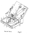
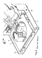
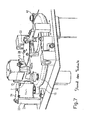
- FIGS. 5, 6 and 7 which is an enlarged view of a part of Fig. 3, a surface detection device 1 is shown with a laser optics 4, from which a laser line beam L emanates.
- the intersection of the laser line beam L with the rectangular image field F originating from the objective defines the measuring field F.
- Each object to be measured must be passed through this measuring field F.
- the "passing through” the measuring field F is accomplished by means of a linear guide 83 (or reference numeral 4 'in Figs. 5 and 6).
- a turntable 33 (or reference numeral 5 in FIGS. 5, 6 and 7) rotates from measuring pot 84 to measuring pot 84 (in FIG Numeral 8 denotes).
- FIG. 3 also in FIG. 5, for example, only two measuring pots 8
- FIG. 8 only two measuring pots 84 are shown in FIG. 3 (also in FIG. 5, for example, only two measuring pots 8), wherein, for example, seven pieces in total can be mounted.
- a measuring pot 84 equipped with a tooth arrives in the measuring field, the rotation of the large turntable 33 (or 5 in FIGS. 5, 6 and 7) stops.
- the turntable 33 thus serves only for positioning the pots 84 (or 8 in FIG. 5) equipped with individual teeth and / or a jaw, which will be discussed later.
- the measurement itself takes place, as explained above, by means of a linear movement of the measuring stage 53 on the linear bearings 83 or 4 '(FIG. 5).
- the pot 84 located in the measuring range can be rotated about its own axis between the individual measurements. This leads eg to eight views or the pot 84 (or 8 in FIG. 5) is rotated between the measurements by 45 ° about its own axis. Thus, in such a case, eight measuring strips arise from different views. Parts of the obtained surface information occur in several gauges. By means of these overlapping areas, suitable devices or methods in the form of, for example, an already explained above matching software to assemble the individual strips to a complete 3D surface image of a single tooth with high accuracy.
- a turntable 5 serves to locate various single tooth measuring cups 8 under the laser measuring arrangement (see FIG 3)
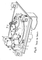
- This turntable 5 is driven by a friction wheel 15 (see Fig. 6).
- This friction wheel 15 is pressed by means of a spring plate 24 (see FIG. 6) on the front side of the turntable 5. As a result, any wear of a rubber surface or the rubber material of the friction wheel 15 is compensated.
- the position of the turntable 5 is detected by means of an encoder disc 28.
- the disc is designed as a sheet 28 (see FIG. 6), which has slots 100 exactly at the locations at which required stop positions lie.
- the slots 100 are detected by means of a light barrier 33 (see FIG. 6).
- a control software evaluates the light barrier signals and starts / stops the Table or plate 5.
- the turntable 5 contains seven positions / pots for single teeth. If a work contains more than seven preparations / teeth (a maximum of 14 per jaw is possible), the work can be scanned in 2 batches.
- a pulley or a toothed belt can be used.
- the frame of the device / the device on two guide rods 83 (see FIGS. 3 and 4) suspended.
- the complete frame of the device thus consists only of two side parts 2 (see FIGS. 3 and 4), the guide rods 83 (see FIGS. 3 and 4) and an optical plate (FIG. 5).
- Inaccuracies caused by the mechanical design of the linear rod guide are compensated by software (e.g., so-called "look-up tables").
- a precision spindle 94 (see Figures 3 and 4) is mounted on the side of the travel table on which the laser assembly is located. Angular errors of the spindle have less effect.
- the advantages of this embodiment are low production costs, high precision, significantly lower transport weight and smaller design.
- a template 54 is required (see FIG. 5). Since there are jaw models with different diameters (eg for children and adults), the jaw model must be adapted according to the size. For this purpose, for example, 3 different adjustment contours I, II and III are engraved on the transparent plexiglass pane, from which the template 54 is preferably formed, or otherwise suitably applied.
- the turntable 5 (FIGS. 5, 6 and 7) transports the individual pots 8 to the measuring position in front of the friction wheel 15. As the turntable 5 moves, the frictional contact of the poppet 8 with the friction wheel 15 is automatically produced.
- the innovation is that the friction wheel 15 is made of rubber or at least has a rubber-running surface, the mating wheel 7, however, made of solid metal. This has the advantages of a lower price, a simple production and a long service life.
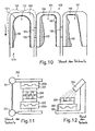
- FIG. 10 Shown are 3 tooth stumps 101, each consisting of a ground part 101a and a residual tooth area 101b.
- the grinding is done manually by a dentist and forcibly leads to undercuts 102, which differ in the shape, location and size when viewing several adjacent individual teeth or their stumps 101
- a so-called coping 104 is first prepared for at least one stump 101, which usually in exactly one Insertion or Aufsteckides according to the arrow E can be pushed over the stump 101. It is not possible that the cap 104 fills the undercuts 102, as a postponement would otherwise no longer be possible.
- 3 stumps 101 are juxtaposed and are combined according to 3 copings 104 to form a bridge, in each case adjacent copings 104 being connected by means of a respective web 105.
- an optimum plug-in or plug-in direction must now be determined, in which the undercuts 102, which are also inclined, for example, by an inclination of a stump 101 with respect to the other stumps 101. as shown in FIG. 10 at the rightmost stump 101, are minimized.
- the WO 02/39056 A1 be used to further improve the approach for the preparation of dental prostheses.
- recommendations can be made for the treating dentist, by which reworking of the tooth stumps an improvement of the seat and stability of the prosthesis to be produced, including a significant reduction of the undercuts or "dead spaces" 102 can be achieved.
- the method according to the WO 02/39056 A1 extended to the effect that with respect to a detected 3D data set of a tooth stump 101 or a combination of multiple tooth stumps 101, an optimal attachment direction for copings 104, in particular a connection of a plurality of copings 104 to a bridge 106, is calculated on the proviso that changes in shape on the stump of the tooth / the tooth stumps 101 are possible.
- the method and system according to WO 02/39056 A1 thus serves not only to determine an adaptation to given circumstances for the production and the attachment of copings 104 or bridges 106, but also to change the given circumstances in order to optimize the result, ie the prosthesis.
- the method and system may include providing a graphical display of the stumps, including, for example, specially colored areas for rework, which serves as the basis for a dialogue between a dental laboratory and a dentist.
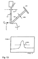
- the light signal to be evaluated on the camera chip contains information essential for the method described: While the laser line touches a surface portion that does not contain an edge, as illustrated in FIG. 13, the full width of the laser beam is reflected.
- FIG. 13 shows a tooth Z with a tooth surface ZO onto which a laser beam LS from a laser light source LQ with a beam width LB impinges.
- the reflected beam RS has a width LBR1, with which it encounters a CCD chip CCD as a detection device.
- the laser beam LS strikes an edge, as shown in FIG.
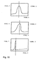
- the shape of the signal to be evaluated likewise changes, as does the representation of the corresponding signals in each case in the lower half of Figures 13 and 14. If a symmetrical Gaussian curve is described for the area (compare Figure 13), the signal runs in 14), as can be seen in FIG.
- FIG. 15 which schematically shows the signal form of a signal 1 resulting from the scanning of a surface (analogous to FIG. 13) of a signal 2 which is obtained on reaching an edge of a hole in a surface, and a signal 3 is sketched, which is obtained directly at an edge of a hole or here specifically a tooth cavity ZK in a surface (analogous to FIG. 14).
- the information of width variation and shape of the signal can be processed to optimally determine the actual edge of the edge K. By repeatedly measuring this edge K from several space angles with the described method, this information can be checked against each other by means of matching methods and determined by averaging in the edge area to its final shape.
- a 3D data set for example a tooth inlay cavity, which has been scanned in this way and which 3D data set has been further processed, for example, by suitable surface triangulation methods, typically contains surfaces which are described by at least three or more corner points. These surfaces are connected by common edges or points, as the graph of FIG. 16 illustrates.
- the described method for partially or fully automatic edge detection and separation now takes place by the a priori information that edges of preparations have above-average, high curvatures or points Have angles.
- a valence of the curvature can subsequently be determined by a difference analysis of the point normal from the normals of the area data sets.
- the following step attempts to increase and classify the significance of various criteria by finding neighborhood relationships.
- one criterion may be the neighborhood relationships with respect to a contiguous line. This is the basic building block for automatic edge detection.
- edges are now optimally analyzed, recognized and merged into a contiguous edge course, as shown schematically in the method step diagrams of FIGS. 17 and 18.
- the dental inlay only the surface segments located within an edge profile are used.
- FIG. 17 a complete dataset of a stump preparation SP with a tooth cavity ZK prepared for an inlay and its edges or edges K is schematically shown below (1.) only in a side view, but in reality it is altogether one 3D dataset acts, so a three-dimensional data representation of the stump preparation.
- step (2) the step of recognizing and separating the edges or edges K is illustrated only schematically in FIG. 17, wherein again the two-dimensional representation for the 3D data set from step (1) of FIG. 17 is representative.
- the edge detection takes place, for example, as explained with reference to FIGS. 13 to 16 and shown in these figures.
- step (3) is further illustrated schematically for simplicity as a two-dimensional representation of the complete 3D dataset, wherein, for example, by importing a database occlusal surface KF, the missing side of the prepared and later inlay becomes the prepared tooth cavity data ZK which otherwise determines the shapes and dimensions of the inlay.
- the sales area data stored in a database eg for the lower molar mandible
- the original tooth shape data measured before the treatment is imported by the dentist, or the measured shape data individually from a dental technician for the inlay imported into wax modeled occlusal surface.
- step (4) of FIG. 18 the data of the imported purchase area KF are linked to the data of the prepared tooth cavity ZK, which in turn is represented on the two-dimensional schematic example as representative of the respective 3D data sets of purchase area KF and tooth cavity ZK.
- the purchase-area data are optimally adapted to the edge and placed on the edge.
- step (5) of FIG. 18 a morphing of the occlusal surface and a separation of the supernatant, so that a finished inlay data set IS is obtained, which, for the sake of simplicity, continues to be only a two-dimensional representation of the actual data set with the complete 3D data is shown.
- the occlusal surface for example, can be adapted to the opposing bite by means of morphing.
- the resulting 3D data set can be used for the CNC production of inlay parts. It is particularly advantageous for the precision of the inlay I, if the holding web HS of the inlay I remaining after the milling process has been completed with a milling tool FW is positioned in the area of the chewing surface KF, as illustrated with reference to FIG. 19.
- Pre-assembled parts are often used in conventional dental technology.
- implant posts, abutments and attachments are mechanically connected to the conventional dentures.
- the invention makes it possible to avoid the process of assembling several prefabricated parts, for example with adhesive. In addition to cost reasons, this also results in an improved health tolerance for the patient, since only one material is inserted into the body. Furthermore, a longer life and higher overall precision is possible.
- a preferred component of the presently treated aspect of the invention is that 3D CAD design data from a prefabricated dental prosthesis or from design elements or fasteners of dental prostheses and 3D measurement data from tooth stumps and / or tooth forms (superfaces) are brought together.
- Fig. 20a exemplifies a conventional end product situation
- Fig. 20b shows a final product situation according to the present invention.
- the method can be applied taking into account the dental situation of the patient.
- measurement data of the alveolar ridge In addition to measurement data of the alveolar ridge, measurement data of neighboring teeth can also be displayed.
- a particular advantage of this method is that the insertion direction can be taken into account in the construction of bedding parts.
- the mix of design data, CAD design tools, 3D matching tools and measurement data processing leads to a multitude of technical possibilities and process flows.
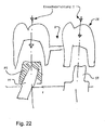
- FIGs. 21a and 21b and 22 Another example of the invention is illustrated in Figs. 21a and 21b and 22:
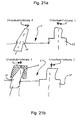
- FIGS. 21a and 21b show an implant abutment PF (with abutment) and a stump ST, which are to be crowned together by means of a bridge.
- another stump can also form the basis for the further procedure, or several parts can be present as two which can be any desired, for example, implant abutments or tooth stumps.
- the situation is for example by means of technology according to the prior art, in particular the WO 02/39056 A1 to obtain 3D data sets of the implant piercer PF in its position and the tooth stump in position and shape. If necessary, it is also possible to detect the shape of the implantate pillar, provided that it is not an assembly part whose 3D data is already present in the system, so that only its position needs to be determined.
- Insertion direction 1 through the stump ST and insertion direction 2 through the implant pier PF.
- the insertion direction 1 is selected for this purpose, which can be realized for example fully automatically by means of the software used, but also semi-automatically selected by selectivity and adjustability within the software limits by an operator and for the additional procedures can be specified.
- a purely manual choice of insertion direction which allows a strong involvement of expert know-how, especially for complicated arrangements.
- a software can calculate a primary part PT according to FIG. 21b which acts to unify the two insertion directions as an adapter on the implant pier PF, so that the insertion direction 2 also applies to the latter.
- margins for the primary part PT or the adapter either fully automatically by the software or semi-automatically, by predetermined margins are set and adjustable within limits, or manually adjusted by the user freely specifying the edges.
- the software can also be defined as a milling direction, specifically as a function of the direction of insertion, but overall, taking into account various parameters, for the tooth replacement part.
- the internal data set is initially used to measure the stump ST, including its surroundings U, in which the implant abutment PF lies.
- the design data set of the implant post PF (with abutment) is loaded and spatially assigned to the measured data by means of a matching process.
- This is to use the data of the design dataset for the CNC manufacturing of the part, as this can achieve a higher precision of the final product than in the processing of measurement data.
- the outer contour of the primary part can also be artificially generated or CAD-constructed, with one or the insertion direction 1 defined by the stump ST being used. Thus, an individual, mechanically precise primary part can be manufactured.
- Essential for the last aspect of the present invention is the use of a primary part as an adapter in order to be able to provide a common insertion direction for a tooth replacement part that concerns a plurality of tooth stumps, implant posts, etc.
- a primary part as an adapter in order to be able to provide a common insertion direction for a tooth replacement part that concerns a plurality of tooth stumps, implant posts, etc.
Landscapes
- Health & Medical Sciences (AREA)
- General Health & Medical Sciences (AREA)
- Veterinary Medicine (AREA)
- Epidemiology (AREA)
- Life Sciences & Earth Sciences (AREA)
- Animal Behavior & Ethology (AREA)
- Oral & Maxillofacial Surgery (AREA)
- Public Health (AREA)
- Dentistry (AREA)
- Physics & Mathematics (AREA)
- Optics & Photonics (AREA)
- Dental Tools And Instruments Or Auxiliary Dental Instruments (AREA)
- Dental Prosthetics (AREA)
- Length Measuring Devices By Optical Means (AREA)
- A Measuring Device Byusing Mechanical Method (AREA)
Applications Claiming Priority (2)
| Application Number | Priority Date | Filing Date | Title |
|---|---|---|---|
| DE20216119 | 2002-10-18 | ||
| EP03776796A EP1558893B1 (fr) | 2002-10-18 | 2003-10-20 | Dispositifs et procede de production de pieces protheses dentaires |
Related Parent Applications (1)
| Application Number | Title | Priority Date | Filing Date |
|---|---|---|---|
| EP03776796A Division EP1558893B1 (fr) | 2002-10-18 | 2003-10-20 | Dispositifs et procede de production de pieces protheses dentaires |
Publications (2)
| Publication Number | Publication Date |
|---|---|
| EP1870667A2 true EP1870667A2 (fr) | 2007-12-26 |
| EP1870667A3 EP1870667A3 (fr) | 2008-03-19 |
Family
ID=32115641
Family Applications (4)
| Application Number | Title | Priority Date | Filing Date |
|---|---|---|---|
| EP06012111.8A Withdrawn EP1754952A3 (fr) | 2002-10-18 | 2003-10-20 | Dispositif et procédé destinés à la fabrication d'éléments de remplacement de dents |
| EP07015279A Withdrawn EP1870667A3 (fr) | 2002-10-18 | 2003-10-20 | Dispositifs et procédés destinés à la détection de surfaces et à la production de pieces protheses dentaires |
| EP03776796A Revoked EP1558893B1 (fr) | 2002-10-18 | 2003-10-20 | Dispositifs et procede de production de pieces protheses dentaires |
| EP06012110.0A Expired - Lifetime EP1762821B1 (fr) | 2002-10-18 | 2003-10-20 | Dispositif et procédé destinés à la fabrication d'éléments de remplacement de dents |
Family Applications Before (1)
| Application Number | Title | Priority Date | Filing Date |
|---|---|---|---|
| EP06012111.8A Withdrawn EP1754952A3 (fr) | 2002-10-18 | 2003-10-20 | Dispositif et procédé destinés à la fabrication d'éléments de remplacement de dents |
Family Applications After (2)
| Application Number | Title | Priority Date | Filing Date |
|---|---|---|---|
| EP03776796A Revoked EP1558893B1 (fr) | 2002-10-18 | 2003-10-20 | Dispositifs et procede de production de pieces protheses dentaires |
| EP06012110.0A Expired - Lifetime EP1762821B1 (fr) | 2002-10-18 | 2003-10-20 | Dispositif et procédé destinés à la fabrication d'éléments de remplacement de dents |
Country Status (8)
| Country | Link |
|---|---|
| US (1) | US7899221B2 (fr) |
| EP (4) | EP1754952A3 (fr) |
| JP (1) | JP4563178B2 (fr) |
| AT (1) | ATE380997T1 (fr) |
| AU (1) | AU2003286094A1 (fr) |
| DE (2) | DE10394004D2 (fr) |
| ES (2) | ES2297241T3 (fr) |
| WO (1) | WO2004038326A2 (fr) |
Cited By (1)
| Publication number | Priority date | Publication date | Assignee | Title |
|---|---|---|---|---|
| DE102013101879A1 (de) * | 2013-02-26 | 2014-08-28 | Heraeus Kulzer Gmbh | Dental-Implantat-System mit Schraube in Passform |
Families Citing this family (40)
| Publication number | Priority date | Publication date | Assignee | Title |
|---|---|---|---|---|
| ATE555743T1 (de) | 2000-11-08 | 2012-05-15 | Straumann Inst Ag | (dentale) oberflächenerfassung und erzeugung |
| WO2004038326A2 (fr) * | 2002-10-18 | 2004-05-06 | Willytec Gmbh | Dispositifs et procede de production de pieces protheses dentaires |
| WO2006005284A2 (fr) * | 2004-06-10 | 2006-01-19 | Willytec Gmbh | Procedes et dispositifs pour realiser une prothese dentaire |
| US7322824B2 (en) * | 2004-08-17 | 2008-01-29 | Schmitt Stephen M | Design and manufacture of dental implant restorations |
| US20060093982A1 (en) * | 2004-11-02 | 2006-05-04 | Huafeng Wen | Method and apparatus for manufacturing and constructing a dental aligner |
| US20060115790A1 (en) * | 2004-11-26 | 2006-06-01 | Michael Alon | Method and accessory for preparing a dental crown or bridge |
| DE102005016245B4 (de) * | 2005-04-08 | 2008-02-21 | Aepsilon Gmbh | Verfahren, Computer und computerlesbares Medium betreffend die Prüfung von Datensätzen für Zahnersatzteile |
| US9504541B2 (en) * | 2006-01-05 | 2016-11-29 | Dentsply International Inc. | Method and system for designing custom restorations for dental implants |
| US8043091B2 (en) * | 2006-02-15 | 2011-10-25 | Voxelogix Corporation | Computer machined dental tooth system and method |
| ES2282037B1 (es) * | 2006-03-08 | 2008-09-16 | Juan Carlos Garcia Aparicio | Procedimiento de fabricacion de protesis dentales removibles diseñadas digitalmente y sistema necesario para tal fin. |
| US7844429B2 (en) | 2006-07-19 | 2010-11-30 | Align Technology, Inc. | System and method for three-dimensional complete tooth modeling |
| JP4481279B2 (ja) * | 2006-08-17 | 2010-06-16 | 株式会社ジーシー | 歯科用補綴物の支台歯対向面切削加工用データ作製支援プログラム |
| WO2008040380A1 (fr) * | 2006-10-07 | 2008-04-10 | 3D Lab Service Gmbh | Procédé de réalisation d'une prothèse dentaire complète |
| US7835811B2 (en) | 2006-10-07 | 2010-11-16 | Voxelogix Corporation | Surgical guides and methods for positioning artificial teeth and dental implants |
| DE102006052420A1 (de) * | 2006-11-07 | 2008-05-08 | Aepsilon Rechteverwaltungs Gmbh | Vorrichtung zum Halten eines Modells |
| DE102006061134A1 (de) * | 2006-12-22 | 2008-06-26 | Aepsilon Rechteverwaltungs Gmbh | Verfahren betreffend den Transport von Zahnersatzteilen |
| DE102006061143A1 (de) * | 2006-12-22 | 2008-07-24 | Aepsilon Rechteverwaltungs Gmbh | Verfahren, computerlesbares Medium und Computer betreffend die Herstellung von Zahnersatzteilen |
| DE102007002178A1 (de) * | 2007-01-03 | 2008-07-10 | Aepsilon Rechteverwaltungs Gmbh | Verfahren betreffend die Modellierung und Herstellung von einem künstlichen Gebiss |
| WO2009032228A2 (fr) * | 2007-08-31 | 2009-03-12 | Dentsply International Inc. | Procédés d'impression en trois dimensions et matériaux pour fabriquer des produits dentaires |
| US20090092948A1 (en) * | 2007-10-03 | 2009-04-09 | Bernard Gantes | Assisted dental implant treatment |
| CA2606267A1 (fr) * | 2007-10-11 | 2009-04-11 | Hydro-Quebec | Systeme et methode de cartographie tridimensionnelle d'une surface structurelle |
| TW200918025A (en) * | 2007-10-25 | 2009-05-01 | Pou Yuen Technology Co Ltd | Design method for digital abutment tooth of digital dental implant technique |
| DE102007054906B4 (de) * | 2007-11-15 | 2011-07-28 | Sirona Dental Systems GmbH, 64625 | Verfahren zur optischen Vermessung der dreidimensionalen Geometrie von Objekten |
| DE102007054907A1 (de) * | 2007-11-15 | 2009-05-28 | Sirona Dental Systems Gmbh | Verfahren zur optischen Vermessung von Objekten unter Verwendung eines Triangulationsverfahrens |
| US7865259B2 (en) * | 2007-12-06 | 2011-01-04 | Align Technology, Inc. | System and method for improved dental geometry representation |
| DE102008006048A1 (de) | 2008-01-25 | 2009-07-30 | Straumann Holding Ag | Verfahren zum Modellieren eines individuellen Zahnersatzes |
| US9707058B2 (en) * | 2009-07-10 | 2017-07-18 | Zimmer Dental, Inc. | Patient-specific implants with improved osseointegration |
| US8348669B1 (en) | 2009-11-04 | 2013-01-08 | Bankruptcy Estate Of Voxelogix Corporation | Surgical template and method for positioning dental casts and dental implants |
| US9879976B2 (en) | 2010-01-20 | 2018-01-30 | Faro Technologies, Inc. | Articulated arm coordinate measurement machine that uses a 2D camera to determine 3D coordinates of smoothly continuous edge features |
| US9607239B2 (en) | 2010-01-20 | 2017-03-28 | Faro Technologies, Inc. | Articulated arm coordinate measurement machine having a 2D camera and method of obtaining 3D representations |
| GB201009999D0 (en) * | 2010-06-15 | 2010-07-21 | Materialise Dental Nv | Custom healing cap for dental implantology and method for design and manufacturing thereof |
| GB201115265D0 (en) * | 2011-09-05 | 2011-10-19 | Materialise Dental Nv | A method and system for 3d root canal treatment planning |
| DE102013211200B4 (de) * | 2013-06-14 | 2018-11-29 | Kulzer Gmbh | Scanbarer Löffel zur Herstellung einer Dentalprothese |
| DK3185813T3 (da) * | 2014-08-29 | 2020-03-23 | Carestream Dental Tech Topco Ltd | Fremgangsmåde til dental virtuel modelbasis |
| US10888395B2 (en) * | 2016-10-28 | 2021-01-12 | Align Technology, Inc. | Mold and aligner with cut line markings |
| EP3385661B1 (fr) * | 2017-04-07 | 2019-08-14 | Faro Technologies, Inc. | Machine de mesure de coordonnées à bras articulé utilisant une caméra 2d pour déterminer des coordonnées 3d de caractéristiques de bords continus et sans à-coups |
| KR101867481B1 (ko) * | 2017-04-17 | 2018-06-15 | 오스템임플란트 주식회사 | 지대치의 축 결정 방법, 장치 및 기록매체 |
| CN108498201A (zh) * | 2018-04-27 | 2018-09-07 | 浦江县安恒进出口有限公司 | 一种牙种植体设备及其使用方法 |
| CN108498202A (zh) * | 2018-04-27 | 2018-09-07 | 浦江县安恒进出口有限公司 | 一种牙种植体设备 |
| JP2022059240A (ja) * | 2020-10-01 | 2022-04-13 | 有限会社ダイトク化研 | 位置決め装置及び歯型模型用位置決め装置 |
Citations (1)
| Publication number | Priority date | Publication date | Assignee | Title |
|---|---|---|---|---|
| EP1062916A2 (fr) * | 1999-06-21 | 2000-12-27 | DCS Forschungs & Entwicklungs AG | Procédé de fabrication personnalisé de prothèses dentaires fixées sur implants et procédé de fabrication d'une prothèse dentaire, en particulier d'une quelconque matière, aussi en matière biocompatible, en particulier à l'aide de la CAD-CAM meulage et fraisage méthode |
Family Cites Families (89)
| Publication number | Priority date | Publication date | Assignee | Title |
|---|---|---|---|---|
| US3861044A (en) * | 1972-05-04 | 1975-01-21 | Jr William E Swinson | Dental fitting process |
| JPS547596U (fr) * | 1977-06-18 | 1979-01-18 | ||
| EP0054785B1 (fr) * | 1980-12-24 | 1985-07-03 | Werner H. Dr.med.dent. Mörmann | Procédé de réalisation d'élements rapportés médicaux et dentaires, alloplastiques, endoprothétiques et exoprothétiques |
| US4575805A (en) * | 1980-12-24 | 1986-03-11 | Moermann Werner H | Method and apparatus for the fabrication of custom-shaped implants |
| DE3203937C2 (de) * | 1982-02-05 | 1985-10-03 | Luc Dr. 4150 Krefeld Barrut | Verfahren und Vorrichtung zum maschinellen Sanieren oder Korrigieren mindestens eines Zahnes oder zum maschinellen Vorbereiten mindestens eines Zahnes für eine festsitzende prothetische Restaurierung und zum maschinellen Herstellen der festsitzenden prothetischen Restaurierung |
| FR2536654B1 (fr) * | 1982-11-30 | 1987-01-09 | Duret Francois | Procede de realisation d'une prothese dentaire |
| US4663720A (en) * | 1984-02-21 | 1987-05-05 | Francois Duret | Method of and apparatus for making a prosthesis, especially a dental prosthesis |
| DE3723555C2 (de) * | 1987-07-16 | 1994-08-11 | Steinbichler Hans | Verfahren zur Herstellung von Zahnersatz |
| FR2639211A1 (fr) * | 1988-11-18 | 1990-05-25 | Hennson Int | Procede de correlation des saisies tridimensionnelles d'organes humains et dispositif pour sa mise en oeuvre |
| US4935635A (en) * | 1988-12-09 | 1990-06-19 | Harra Dale G O | System for measuring objects in three dimensions |
| US5184306A (en) * | 1989-06-09 | 1993-02-02 | Regents Of The University Of Minnesota | Automated high-precision fabrication of objects of complex and unique geometry |
| US5347454A (en) * | 1990-04-10 | 1994-09-13 | Mushabac David R | Method, system and mold assembly for use in preparing a dental restoration |
| SE468198B (sv) | 1990-12-12 | 1992-11-23 | Nobelpharma Ab | Foerfarande och anordning foer framstaellning av individuellt utformade tredimensionella kroppar anvaendbara som tandersaettningar, proteser, etc |
| JPH0824685B2 (ja) * | 1992-11-25 | 1996-03-13 | 株式会社江川 | インプラント構造体の測定方法およびその測定装置 |
| SE501820C2 (sv) | 1993-05-21 | 1995-05-22 | Tritech Mekatronik Ab | Metod och anordning för att skapa en modell av en tandrestauration |
| SE501411C2 (sv) | 1993-07-12 | 1995-02-06 | Nobelpharma Ab | Förfarande och anordning vid tredimensionell kropp användbar i människokroppen |
| NL9301308A (nl) * | 1993-07-26 | 1995-02-16 | Willem Frederick Van Nifterick | Werkwijze voor het vastzetten van een tandprothese op implantaten in het kaakbeen van een patiënt en middel te gebruiken daarbij. |
| US5338198A (en) * | 1993-11-22 | 1994-08-16 | Dacim Laboratory Inc. | Dental modeling simulator |
| US5873721A (en) * | 1993-12-23 | 1999-02-23 | Adt Advanced Dental Technologies, Ltd. | Implant abutment systems, devices, and techniques |
| SE502427C2 (sv) * | 1994-02-18 | 1995-10-16 | Nobelpharma Ab | Metod och anordning utnyttjande artikulator och datorutrustning |
| SE503073C2 (sv) * | 1994-07-04 | 1996-03-18 | Nobelpharma Ab | Metod för framställning av långsträckt stöddel i ersättningsuppbyggnad samt sådan stöddel tillverkad med metoden |
| DE4439307C2 (de) | 1994-11-03 | 1999-07-29 | Albert Dr Mehl | Beobachtungsoptik für ein 3D-Oberflächenmeßgerät mit hoher Genauigkeit |
| DE19524855A1 (de) * | 1995-07-07 | 1997-01-09 | Siemens Ag | Verfahren und Vorrichtung zur rechnergestützten Restauration von Zähnen |
| DE69626287T2 (de) * | 1995-07-21 | 2003-11-27 | Cadent Ltd., Or Yehuda | Verfahren und system zur dreidimensionalen bilderfassung von zähnen |
| US5718585A (en) * | 1995-09-15 | 1998-02-17 | Dentsply Research & Development Corp. | Prosthetic teeth and mold making therefor |
| DE19605741C1 (de) | 1996-02-16 | 1997-07-24 | Wolfgang Dr Fleckenstein | Gehirn-pO2-Meßvorrichtung mit Eingabeeinrichtung |
| US6044170A (en) | 1996-03-21 | 2000-03-28 | Real-Time Geometry Corporation | System and method for rapid shape digitizing and adaptive mesh generation |
| JPH1075963A (ja) * | 1996-09-06 | 1998-03-24 | Nikon Corp | 歯科補綴物モデルの設計方法およびこの方法を実行するプログラムを記録した媒体 |
| DE19642247C1 (de) | 1996-10-12 | 1998-01-15 | Sebastian Meller | Verfahren zur Herstellung eines Zahnersatzteils |
| US5690490A (en) * | 1996-11-25 | 1997-11-25 | Cannon; Mark L. | Method and apparatus for fabrication of dental restoration by pinhead molding |
| US6231339B1 (en) * | 1997-01-15 | 2001-05-15 | Floyd E. Skarky | Dental device for positioning the mandible and the maxilla in centric relation and methods for using same |
| DE19721688B4 (de) | 1997-03-06 | 2012-12-27 | Institut Straumann Ag | Oberflächenerfassungseinrichtung und Verfahren zur Oberflächenerfassung |
| DE19710273C1 (de) | 1997-03-13 | 1998-08-20 | Heraeus Kulzer Gmbh | Verfahren und Vorrichtung zur Bearbeitung von Werkstücken in der Dentaltechnik |
| SE509141C2 (sv) | 1997-04-10 | 1998-12-07 | Nobel Biocare Ab | Arrangemang och system för dental produktframställning och informationsgivning |
| US6409504B1 (en) * | 1997-06-20 | 2002-06-25 | Align Technology, Inc. | Manipulating a digital dentition model to form models of individual dentition components |
| US5989029A (en) * | 1997-07-08 | 1999-11-23 | Atlantis Components, Inc. | Customized dental abutments and methods of preparing or selecting the same |
| US20020036617A1 (en) * | 1998-08-21 | 2002-03-28 | Timothy R. Pryor | Novel man machine interfaces and applications |
| DK0913130T3 (da) * | 1997-10-31 | 2003-06-16 | Dcs Forschungs & Entwicklungs | Fremgangsmåde og apparat til fremstilling af en tanderstatningsdel |
| US6416319B1 (en) * | 1998-02-13 | 2002-07-09 | Britesmile, Inc. | Tooth whitening device and method of using same |
| WO1999061202A1 (fr) | 1998-05-28 | 1999-12-02 | Kabushiki Kaisya Advance | Procede et dispositif de façonnage d'appareil de prothese et bloc pour prothese |
| IL125659A (en) * | 1998-08-05 | 2002-09-12 | Cadent Ltd | Method and device for three-dimensional simulation of a structure |
| JP2000185060A (ja) * | 1998-10-13 | 2000-07-04 | Nikon Corp | 歯牙のマ―ジンライン抽出法 |
| DE19901643A1 (de) * | 1999-01-19 | 2000-07-20 | Herbst Bremer Goldschlaegerei | Verfahren zur Herstellung von Zahnersatz und dentalen Hilfsteilen |
| JP2001166810A (ja) * | 1999-02-19 | 2001-06-22 | Sanyo Electric Co Ltd | 立体モデル提供装置及び方法 |
| US6532299B1 (en) * | 2000-04-28 | 2003-03-11 | Orametrix, Inc. | System and method for mapping a surface |
| US7068825B2 (en) * | 1999-03-08 | 2006-06-27 | Orametrix, Inc. | Scanning system and calibration method for capturing precise three-dimensional information of objects |
| US6851949B1 (en) * | 1999-11-30 | 2005-02-08 | Orametrix, Inc. | Method and apparatus for generating a desired three-dimensional digital model of an orthodontic structure |
| JP3621046B2 (ja) * | 1999-04-16 | 2005-02-16 | カルテンバッハ ウント ホイクト ゲゼルシャフト ミット ベシュレンクテル ハフツング ウント カンパニー カーゲー | セラミックから医療、歯科医療、歯科技術および技術用の部品を製造する方法 |
| DE19930564A1 (de) | 1999-04-16 | 2000-10-19 | Kaltenbach & Voigt | Verfahren zur Herstellung medizinischer, zahnmedizinischer, zahntechnischer und technischer Teile aus Keramik |
| TW461806B (en) | 1999-08-02 | 2001-11-01 | Advance Kk | Method of manufacturing dental prosthesis, method of placing object and measuring device |
| SE515307C2 (sv) * | 1999-11-05 | 2001-07-09 | Nobel Biocare Ab | Metod och anordning för framställning av modell till ersättningsdel i människokroppen |
| DK1235532T3 (da) * | 1999-12-07 | 2005-09-19 | Inocermic Ges Fuer Innovative | Fremgangsmåde til fremstilling af en keramisk tandprotese |
| US7373286B2 (en) * | 2000-02-17 | 2008-05-13 | Align Technology, Inc. | Efficient data representation of teeth model |
| US6463344B1 (en) * | 2000-02-17 | 2002-10-08 | Align Technology, Inc. | Efficient data representation of teeth model |
| US7084868B2 (en) * | 2000-04-26 | 2006-08-01 | University Of Louisville Research Foundation, Inc. | System and method for 3-D digital reconstruction of an oral cavity from a sequence of 2-D images |
| US7027642B2 (en) * | 2000-04-28 | 2006-04-11 | Orametrix, Inc. | Methods for registration of three-dimensional frames to create three-dimensional virtual models of objects |
| US6832877B2 (en) | 2000-05-29 | 2004-12-21 | Kabushiki Kaisya Advance | Dental measuring and machining system |
| WO2002009612A1 (fr) | 2000-07-31 | 2002-02-07 | O'brien Dental Lab, Inc. | Blocs de fraisage destines a la fabrication de protheses dentaires, protheses dentaires associees et leurs procedes de fabrication |
| US7106885B2 (en) * | 2000-09-08 | 2006-09-12 | Carecord Technologies, Inc. | Method and apparatus for subject physical position and security determination |
| KR100382905B1 (ko) * | 2000-10-07 | 2003-05-09 | 주식회사 케이씨아이 | 치아 컴퓨터 모델링용 삼차원 스캐너 시스템 |
| US6364660B1 (en) * | 2000-10-25 | 2002-04-02 | Duane Milford Durbin | Method and system for imaging and modeling dental structures |
| ATE555743T1 (de) * | 2000-11-08 | 2012-05-15 | Straumann Inst Ag | (dentale) oberflächenerfassung und erzeugung |
| US6579095B2 (en) * | 2000-12-22 | 2003-06-17 | Geodigm Corporation | Mating parts scanning and registration methods |
| US6506054B2 (en) * | 2001-03-20 | 2003-01-14 | Itzhak Shoher | Method of forming a dental coping |
| SE523022C3 (sv) | 2001-03-23 | 2004-04-14 | Cad Esthetics Ab | Förfarande och anordning för en dental restauration |
| US7065243B2 (en) * | 2001-06-28 | 2006-06-20 | Eastman Kodak Company | Method and system for creating dental models from imagery |
| JP2004534608A (ja) * | 2001-07-13 | 2004-11-18 | デグデント・ゲーエムベーハー | 三次元で測定及びデジタル化した陽性モデルに基づく義歯の作成 |
| DE10133568A1 (de) * | 2001-07-13 | 2003-01-30 | Degussa Dental Gmbh & Co Kg | Verfahren und Vorrichtung zur dreidimensionalen Vermessung und Digitalisierung eines Körpers |
| EP1420714B1 (fr) | 2001-08-31 | 2007-03-21 | Cynovad, Inc. | Procede de production de moules a fondre |
| SE521327C2 (sv) | 2001-09-19 | 2003-10-21 | Decim Ab | Förfarande för framställning av en dental restauration som fästs i ett käkben |
| WO2004038326A2 (fr) | 2002-10-18 | 2004-05-06 | Willytec Gmbh | Dispositifs et procede de production de pieces protheses dentaires |
| WO2003057067A1 (fr) | 2002-01-14 | 2003-07-17 | Arnold Wohlwend | Procede de production d'une prothese dentaire |
| US6694212B1 (en) * | 2002-03-27 | 2004-02-17 | James P. Kennedy | Computer-aided design of a pontic with retainers |
| DE10214968B4 (de) | 2002-04-04 | 2004-07-01 | Griesbeck, Anton, Dr.med.dent. | Verfahren und Vorrichtung zur Rekonstruktion okklusaler Strukturen |
| GB0213774D0 (en) * | 2002-06-15 | 2002-07-24 | Osseobiotek Ltd | Prosthesis |
| EP2465464B1 (fr) | 2002-10-03 | 2018-08-22 | Align Technology, Inc. | Procédé de préparation d'un modèle physique |
| EP1437981B1 (fr) | 2002-10-23 | 2008-08-20 | Dentsply International, Inc. | Protheses dentaires et procede de realisation |
| DE10252298B3 (de) * | 2002-11-11 | 2004-08-19 | Mehl, Albert, Prof. Dr. Dr. | Verfahren zur Herstellung von Zahnersatzteilen oder Zahnrestaurationen unter Verwendung elektronischer Zahndarstellungen |
| DE10300301B4 (de) * | 2003-01-02 | 2009-07-02 | Sirona Dental Systems Gmbh | Verfahren zur automatischen Erzeugung einer dentalen Suprastruktur zur Verbindung mit einem Implantat |
| EP1506745A1 (fr) | 2003-08-15 | 2005-02-16 | Jeanette Mörmann | Ebauche et procédé de fabrication d'une restauration dentaire |
| US7342668B2 (en) * | 2003-09-17 | 2008-03-11 | D4D Technologies, Llc | High speed multiple line three-dimensional digitalization |
| US7330577B2 (en) * | 2004-01-27 | 2008-02-12 | Densys Ltd. | Three-dimensional modeling of the oral cavity by projecting a two-dimensional array of random patterns |
| WO2006005284A2 (fr) | 2004-06-10 | 2006-01-19 | Willytec Gmbh | Procedes et dispositifs pour realiser une prothese dentaire |
| US7236842B2 (en) * | 2004-12-02 | 2007-06-26 | Cadent Ltd. | System and method for manufacturing a dental prosthesis and a dental prosthesis manufactured thereby |
| US7609875B2 (en) * | 2005-05-27 | 2009-10-27 | Orametrix, Inc. | Scanner system and method for mapping surface of three-dimensional object |
| US7698014B2 (en) * | 2006-01-20 | 2010-04-13 | 3M Innovative Properties Company | Local enforcement of accuracy in fabricated models |
| US7711447B2 (en) * | 2006-10-20 | 2010-05-04 | Align Technology, Inc. | System and method for automated generating of a cutting curve on a surface |
| DE102006061143A1 (de) * | 2006-12-22 | 2008-07-24 | Aepsilon Rechteverwaltungs Gmbh | Verfahren, computerlesbares Medium und Computer betreffend die Herstellung von Zahnersatzteilen |
| DE102006061134A1 (de) * | 2006-12-22 | 2008-06-26 | Aepsilon Rechteverwaltungs Gmbh | Verfahren betreffend den Transport von Zahnersatzteilen |
-
2003
- 2003-10-20 WO PCT/DE2003/003462 patent/WO2004038326A2/fr not_active Ceased
- 2003-10-20 JP JP2004545712A patent/JP4563178B2/ja not_active Expired - Fee Related
- 2003-10-20 EP EP06012111.8A patent/EP1754952A3/fr not_active Withdrawn
- 2003-10-20 AU AU2003286094A patent/AU2003286094A1/en not_active Abandoned
- 2003-10-20 EP EP07015279A patent/EP1870667A3/fr not_active Withdrawn
- 2003-10-20 ES ES03776796T patent/ES2297241T3/es not_active Expired - Lifetime
- 2003-10-20 EP EP03776796A patent/EP1558893B1/fr not_active Revoked
- 2003-10-20 DE DE10394004T patent/DE10394004D2/de not_active Withdrawn - After Issue
- 2003-10-20 EP EP06012110.0A patent/EP1762821B1/fr not_active Expired - Lifetime
- 2003-10-20 DE DE50308814T patent/DE50308814D1/de not_active Expired - Lifetime
- 2003-10-20 AT AT03776796T patent/ATE380997T1/de not_active IP Right Cessation
- 2003-10-20 ES ES06012110T patent/ES2785650T3/es not_active Expired - Lifetime
-
2005
- 2005-03-31 US US11/095,027 patent/US7899221B2/en active Active
Patent Citations (1)
| Publication number | Priority date | Publication date | Assignee | Title |
|---|---|---|---|---|
| EP1062916A2 (fr) * | 1999-06-21 | 2000-12-27 | DCS Forschungs & Entwicklungs AG | Procédé de fabrication personnalisé de prothèses dentaires fixées sur implants et procédé de fabrication d'une prothèse dentaire, en particulier d'une quelconque matière, aussi en matière biocompatible, en particulier à l'aide de la CAD-CAM meulage et fraisage méthode |
Cited By (1)
| Publication number | Priority date | Publication date | Assignee | Title |
|---|---|---|---|---|
| DE102013101879A1 (de) * | 2013-02-26 | 2014-08-28 | Heraeus Kulzer Gmbh | Dental-Implantat-System mit Schraube in Passform |
Also Published As
| Publication number | Publication date |
|---|---|
| US7899221B2 (en) | 2011-03-01 |
| JP4563178B2 (ja) | 2010-10-13 |
| EP1558893B1 (fr) | 2007-12-12 |
| JP2006502817A (ja) | 2006-01-26 |
| EP1754952A3 (fr) | 2013-05-22 |
| AU2003286094A1 (en) | 2004-05-13 |
| WO2004038326A2 (fr) | 2004-05-06 |
| EP1870667A3 (fr) | 2008-03-19 |
| EP1558893A2 (fr) | 2005-08-03 |
| AU2003286094A8 (en) | 2004-05-13 |
| DE10394004D2 (de) | 2005-09-08 |
| EP1754952A2 (fr) | 2007-02-21 |
| US20050214716A1 (en) | 2005-09-29 |
| ES2785650T3 (es) | 2020-10-07 |
| EP1762821A3 (fr) | 2013-05-22 |
| EP1762821A2 (fr) | 2007-03-14 |
| DE50308814D1 (de) | 2008-01-24 |
| EP1762821B1 (fr) | 2020-03-18 |
| WO2004038326A3 (fr) | 2004-10-14 |
| ATE380997T1 (de) | 2007-12-15 |
| ES2297241T3 (es) | 2008-05-01 |
Similar Documents
| Publication | Publication Date | Title |
|---|---|---|
| EP1558893B1 (fr) | Dispositifs et procede de production de pieces protheses dentaires | |
| EP1362218B1 (fr) | Releve et realisation de surfaces (dentaires) | |
| EP2673747B1 (fr) | Procédé et système d'analyse pour l'analyse géométrique de données de balayage de structures orales | |
| DE10252298B3 (de) | Verfahren zur Herstellung von Zahnersatzteilen oder Zahnrestaurationen unter Verwendung elektronischer Zahndarstellungen | |
| EP2661732B1 (fr) | Procédé et système d'identification de restaurations dentaires, destinés à identifier des restaurations dentaires | |
| EP3388021B1 (fr) | Procédé de détermination automatique d'une direction d'insertion pour une prothèse dentaire | |
| EP1782753B1 (fr) | Procédé et dispositif destiné à la fabrication de prothèses dentaires | |
| EP1903979A1 (fr) | Procede et dispositif de fabrication de protheses dentaires | |
| EP0250993A2 (fr) | Méthode et appareil pour déterminer et représenter la forme de dents (d'une dent ) taillée(s) en trois dimensions. | |
| DE102005016245B4 (de) | Verfahren, Computer und computerlesbares Medium betreffend die Prüfung von Datensätzen für Zahnersatzteile | |
| DE60223230T2 (de) | Verfahren zur herstellung von dentalen restaurationselementen |
Legal Events
| Date | Code | Title | Description |
|---|---|---|---|
| PUAI | Public reference made under article 153(3) epc to a published international application that has entered the european phase |
Free format text: ORIGINAL CODE: 0009012 |
|
| AC | Divisional application: reference to earlier application |
Ref document number: 1558893 Country of ref document: EP Kind code of ref document: P |
|
| AK | Designated contracting states |
Kind code of ref document: A2 Designated state(s): AT BE BG CH CY CZ DE DK EE ES FI FR GB GR HU IE IT LI LU MC NL PT RO SE SI SK TR |
|
| PUAL | Search report despatched |
Free format text: ORIGINAL CODE: 0009013 |
|
| AK | Designated contracting states |
Kind code of ref document: A3 Designated state(s): AT BE BG CH CY CZ DE DK EE ES FI FR GB GR HU IE IT LI LU MC NL PT RO SE SI SK TR |
|
| 17P | Request for examination filed |
Effective date: 20080915 |
|
| 17Q | First examination report despatched |
Effective date: 20081009 |
|
| AKX | Designation fees paid |
Designated state(s): AT BE BG CH CY CZ DE DK EE ES FI FR GB GR HU IE IT LI LU MC NL PT RO SE SI SK TR |
|
| RAP1 | Party data changed (applicant data changed or rights of an application transferred) |
Owner name: INSTITUT STRAUMANN AG |
|
| STAA | Information on the status of an ep patent application or granted ep patent |
Free format text: STATUS: THE APPLICATION IS DEEMED TO BE WITHDRAWN |
|
| 18D | Application deemed to be withdrawn |
Effective date: 20180906 |