EP1870796A2 - Speichersystem und Speichersteuerverfahren zum Erreichen von sowohl Energieeinsparung als guter Leistungsfähigkeit - Google Patents
Speichersystem und Speichersteuerverfahren zum Erreichen von sowohl Energieeinsparung als guter Leistungsfähigkeit Download PDFInfo
- Publication number
- EP1870796A2 EP1870796A2 EP06255775A EP06255775A EP1870796A2 EP 1870796 A2 EP1870796 A2 EP 1870796A2 EP 06255775 A EP06255775 A EP 06255775A EP 06255775 A EP06255775 A EP 06255775A EP 1870796 A2 EP1870796 A2 EP 1870796A2
- Authority
- EP
- European Patent Office
- Prior art keywords
- power consumption
- value
- controller
- power
- control
- Prior art date
- Legal status (The legal status is an assumption and is not a legal conclusion. Google has not performed a legal analysis and makes no representation as to the accuracy of the status listed.)
- Withdrawn
Links
Images





Classifications
-
- G—PHYSICS
- G06—COMPUTING OR CALCULATING; COUNTING
- G06F—ELECTRIC DIGITAL DATA PROCESSING
- G06F1/00—Details not covered by groups G06F3/00 - G06F13/00 and G06F21/00
- G06F1/26—Power supply means, e.g. regulation thereof
- G06F1/32—Means for saving power
- G06F1/3203—Power management, i.e. event-based initiation of a power-saving mode
- G06F1/3206—Monitoring of events, devices or parameters that trigger a change in power modality
- G06F1/3215—Monitoring of peripheral devices
- G06F1/3221—Monitoring of peripheral devices of disk drive devices
-
- G—PHYSICS
- G06—COMPUTING OR CALCULATING; COUNTING
- G06F—ELECTRIC DIGITAL DATA PROCESSING
- G06F1/00—Details not covered by groups G06F3/00 - G06F13/00 and G06F21/00
- G06F1/26—Power supply means, e.g. regulation thereof
- G06F1/32—Means for saving power
- G06F1/3203—Power management, i.e. event-based initiation of a power-saving mode
- G06F1/3234—Power saving characterised by the action undertaken
- G06F1/325—Power saving in peripheral device
- G06F1/3268—Power saving in hard disk drive
-
- G—PHYSICS
- G06—COMPUTING OR CALCULATING; COUNTING
- G06F—ELECTRIC DIGITAL DATA PROCESSING
- G06F3/00—Input arrangements for transferring data to be processed into a form capable of being handled by the computer; Output arrangements for transferring data from processing unit to output unit, e.g. interface arrangements
- G06F3/06—Digital input from, or digital output to, record carriers, e.g. RAID, emulated record carriers or networked record carriers
- G06F3/0601—Interfaces specially adapted for storage systems
- G06F3/0602—Interfaces specially adapted for storage systems specifically adapted to achieve a particular effect
- G06F3/0625—Power saving in storage systems
-
- G—PHYSICS
- G06—COMPUTING OR CALCULATING; COUNTING
- G06F—ELECTRIC DIGITAL DATA PROCESSING
- G06F3/00—Input arrangements for transferring data to be processed into a form capable of being handled by the computer; Output arrangements for transferring data from processing unit to output unit, e.g. interface arrangements
- G06F3/06—Digital input from, or digital output to, record carriers, e.g. RAID, emulated record carriers or networked record carriers
- G06F3/0601—Interfaces specially adapted for storage systems
- G06F3/0628—Interfaces specially adapted for storage systems making use of a particular technique
- G06F3/0653—Monitoring storage devices or systems
-
- G—PHYSICS
- G06—COMPUTING OR CALCULATING; COUNTING
- G06F—ELECTRIC DIGITAL DATA PROCESSING
- G06F3/00—Input arrangements for transferring data to be processed into a form capable of being handled by the computer; Output arrangements for transferring data from processing unit to output unit, e.g. interface arrangements
- G06F3/06—Digital input from, or digital output to, record carriers, e.g. RAID, emulated record carriers or networked record carriers
- G06F3/0601—Interfaces specially adapted for storage systems
- G06F3/0628—Interfaces specially adapted for storage systems making use of a particular technique
- G06F3/0655—Vertical data movement, i.e. input-output transfer; data movement between one or more hosts and one or more storage devices
- G06F3/0659—Command handling arrangements, e.g. command buffers, queues, command scheduling
-
- G—PHYSICS
- G06—COMPUTING OR CALCULATING; COUNTING
- G06F—ELECTRIC DIGITAL DATA PROCESSING
- G06F3/00—Input arrangements for transferring data to be processed into a form capable of being handled by the computer; Output arrangements for transferring data from processing unit to output unit, e.g. interface arrangements
- G06F3/06—Digital input from, or digital output to, record carriers, e.g. RAID, emulated record carriers or networked record carriers
- G06F3/0601—Interfaces specially adapted for storage systems
- G06F3/0668—Interfaces specially adapted for storage systems adopting a particular infrastructure
- G06F3/0671—In-line storage system
- G06F3/0683—Plurality of storage devices
- G06F3/0689—Disk arrays, e.g. RAID, JBOD
-
- Y—GENERAL TAGGING OF NEW TECHNOLOGICAL DEVELOPMENTS; GENERAL TAGGING OF CROSS-SECTIONAL TECHNOLOGIES SPANNING OVER SEVERAL SECTIONS OF THE IPC; TECHNICAL SUBJECTS COVERED BY FORMER USPC CROSS-REFERENCE ART COLLECTIONS [XRACs] AND DIGESTS
- Y02—TECHNOLOGIES OR APPLICATIONS FOR MITIGATION OR ADAPTATION AGAINST CLIMATE CHANGE
- Y02D—CLIMATE CHANGE MITIGATION TECHNOLOGIES IN INFORMATION AND COMMUNICATION TECHNOLOGIES [ICT], I.E. INFORMATION AND COMMUNICATION TECHNOLOGIES AIMING AT THE REDUCTION OF THEIR OWN ENERGY USE
- Y02D10/00—Energy efficient computing, e.g. low power processors, power management or thermal management
Definitions
- the present invention relates to controlling the power consumption of a storage system having a plurality of storage devices therein.
- One method of increasing the capacity of a storage system is to increase the number of storage devices installed therein.
- Examples of storage devices are disk devices (e. g. hard disk drives).
- disk devices e. g. hard disk drives
- a large amount of power is consumed in rotating a disk, and hence upon increasing the number of disk devices, the overall power consumption of the storage system increases.
- large-scale equipment investment may be necessary (e.g. it may be necessary to make increases in a power distribution panel in a building in which the storage system is installed).
- control of disk device power saving is carried out (through selection of power supply on/off or a power saving mode). Moreover, in the case that there is access from the host device, if the power supply of the disk device to be accessed is off, then the power supply of that disk device is turned on, and then the access is carried out.
- a microprocessor in a storage system monitors the current capacity used during spindle startup of each of groups of disk devices, and upon detecting that the current consumption has increased, cancels spindle startup for disk devices, thus carrying out control such that the current consumption is not more than a threshold value.
- a storage system In an operating state after having been started up, a storage system can receive an IO command (a data write command or read command) from a host device, and process the received IO command.
- an IO command a data write command or read command
- it is necessary to not only save on power consumption, but also maintain performance (e.g. IO command processing performance) at a certain level.
- performance e.g. IO command processing performance
- it is thus necessary to achieve both power saving and good performance.
- art for realizing this cannot be elicited from document 1, document 2, or a combination thereof.
- a storage system is a storage system connected to a host device from which an IO command is sent, the storage system comprising a plurality of load devices that act as loads including a plurality of storage devices, a current measuring unit that measures a current value flowing into the plurality of load devices, a power calculating unit that calculates at each time a power consumption value consumed by the plurality of load devices based on the measured current value, and a controller that receives the IO command from the host device, and accesses a storage device that follows the IO command out of the plurality of storage devices.
- the controller carries out power consumption control such that the calculated power consumption value is not more than a predetermined allowed power value and a difference between the power consumption value and the allowed power value is reduced.
- the difference ... is reduced means, for example, that in the case that the power consumption value this time is lower than the power consumption value after the power consumption control last time, and so the difference between the power consumption value and the allowed power value this time has become greater than the difference between the power consumption value and the allowed power value after the power consumption control last time, this difference is reduced.
- the power consumption control comprises carrying out power consumption suppression control in which the power consumption value is suppressed but a load device operating state is degraded, and releasing the power consumption suppression control, so as to adjust the number of times that the power consumption suppression control is carried out. For example, in the case that the difference between the power consumption value and the allowed power value this time has become greater than the difference between the power consumption value and the allowed power value after the power consumption control last time, this difference can be reduced by stopping the power consumption suppression control being carried out. Moreover, in the case, for example, that the power consumption value this time exceeds the allowed power value, the power consumption value can be reduced by carrying out the power consumption suppression control.
- the storage system further comprises a basic subsystem having at least the controller therein, and an additional subsystem connected to the basic subsystem.
- the allowed power value is prepared taking each subsystem as a unit.
- the additional subsystem comprises at least two load devices including at least two storage devices, a second controller that communicates with the controller, and a second current measuring unit that measures a current value flowing into the at least two load devices.
- the second controller acquires from the second current measuring unit a second current value which is the current measured by the second current measuring unit.
- the controller acquires the second current value from the second controller, calculates a power consumption value for the second controller based on the second current value, and carries out the power consumption control for each subsystem separately in accordance with the calculated power consumption value and which subsystem this power consumption value is for.
- the controller carries out, as the power consumption suppression control, IO processing control of delaying commencement of IO processing according to the received IO command.
- each of the plurality of storage devices is a disk drive having a rotating disk as a storage medium.
- the controller prioritizes processing an IO command for sequential access over an IO command for random access.
- the controller prioritizes processing an IO command for which a storage device to be accessed is in a high operating state over an IO command for which a storage device to be accessed is in a low operating state.
- the high operating state may mean, for example, the power supply being on, or if the storage device is a disk drive, the disk rotational speed being high.
- the low operating state may mean, for example, the power supply being off, or if the storage device is a disk drive, the disk rotational speed being low (this rotational speed may be zero).
- the storage system further comprises a cache memory.
- the controller is constructed so as to write data to the cache memory in accordance with an IO command from the host device, and write the data written to the cache memory to a storage device that is tobe accessed according to the IO command.
- the controller carries out cache control of controlling an order of writing to the storage devices from the cache memory.
- the controller in the case of the sixth embodiment, in the cache control, out of a plurality of data in the cache memory, the controller prioritizes writing data that is to be written to a storage device in a high operating state over data that is to be written to a storage device in a low operating state.
- the controller carries out storage device control of putting a storage device operating state into a low operating state.
- the controller decides the storage device to be put into the low operating state based on at least one of an access frequency and whether or not there has been access recently for each of the plurality of storage devices.
- the plurality of storage devices include a first storage device and a second storage device.
- the controller carries out processing of putting the first storage device into a high operating state, moving data in the second storage device into the first storage device, and putting the second storage device from which the data has been moved into a low operating state.
- the first storage device is provided in a basic subsystem having the controller therein.
- the second storage device is provided in an additional subsystem connected to the basic subsystem.
- At least two storage device groups are formed from the plurality of storage devices.
- Each of the storage device groups is constituted from a predetermined number of at least two of the storage devices.
- the controller controls the storage device operating state taking the storage device groups as units.
- the controller determines whether or not a power consumption value predicted to increase due to the storage device being put into a high operating state is not more than the allowed power value, and if the predicted power consumption value is not more than the allowed power value, puts the storage device into the high operating state and then accesses the storage device.
- the power calculating unit upon at least one change out of adding, removing, and blocking a load device, acquires a current value and calculates a power consumption value after the change.
- the controller carries out the power consumption control based on the power consumption value calculated after the change.
- the storage system further comprises a power supply unit that supplies power to the plurality of load devices.
- the current measuring unit is provided in the power supply unit.
- the plurality of load devices include first load devices and second load devices.
- the storage system is constructed from a basic subsystem and an additional subsystem connected to the basic subsystem.
- the allowed power value is prepared taking each subsystem as a unit.
- the basic subsystem comprises the controller, at least two of the first load devices, and a first power supply unit that supplies power to the at least two first load devices.
- the first power supply unit has therein a first current measuring unit that measures a current flowing into the at least two first load devices.
- the additional subsystem comprises at least two of the second load devices including at least two storage devices, a second controller that communicates with the controller, and a second power supply unit that supplies power to the at least two second load devices.
- the second power supply unit has therein a second current measuring unit that measures a current value flowing into the at least two second load devices.
- the second controller acquires from the second current measuring unit a second current value which is the current value measured by the second current measuring unit.
- the controller acquires the second current value from the second controller, calculates a power consumption value for the second controller based on the second current value, and carries out the power consumption control for each subsystem separately in accordance with the calculated power consumption value and which subsystem this power consumption value is for.
- the power consumption control comprises carrying out power consumption suppression control in which the power consumption value is suppressed but a load device operating state is degraded, and releasing the power consumption suppression control, so as to adjust the number of times that the power consumption suppression control is carried out.
- a management computer is a computer connected to a storage system as described above, the management computer comprising a storage resource, an allowed value setting unit that sets the allowed power value into the storage system, a power consumption management unit that acquires the power consumption value calculated at each time and records the power consumption value in the storage resource, and a display control unit that displays the recorded power consumption value.
- the management computer further comprises an IO monitoring unit that acquires the number of IO processing instances in each time period, and records in the storage resource a relationship between the time period and the number of IO processing instances.
- the display control unit displays a relationship between the number of IO processing instances in each time period and the power consumption value at each time.
- the display control unit may display in the same display area a graph of the number of IO processing instances in each time period and a graph of the power consumption value at each time.
- Each of the above units of the storage system and the management computer can be realized by hardware (e.g. a circuit), a computer program, or a combination thereof (e.g. at least one CPU that reads in and executes a computer program).
- Each computer program can be read in from a storage resource (e.g. a memory) provided in a computer.
- a storage resource includes installing via a recording medium such as a CD-ROM or a DVD (Digital Versatile Disk), and downloading via a communication network such as an internet or a LAN.
- FIG. 1 is a diagram showing an example of the construction of a storage system according to an embodiment of the present invention.
- the storage system 107 has connected thereto a host computer 103, which is a type of host device, and a computer (hereinafter "management terminal") 105 for managing the storage system 107.
- a host computer 103 which is a type of host device
- a computer (hereinafter "management terminal") 105 for managing the storage system 107.
- the host computer 103 issues IO (input/output) commands to the storage system 107.
- the IO commands are, for example, at least one of write commands for writing data to the storage system, and read commands for reading data from the storage system.
- the management terminal 105 is able to set various information in the storage system 107, and receive and store various information from the storage system 107.
- the function of the management terminal 105 will be described in detail later.
- the storage system 107 can be constructed from at least a basic casing 101 out of the basic casing 101 and additional casings 131.
- additional casing(s) 131 is/are provided, the number of additional casing(s) 131 can be made to be from 1 upward.
- the one or more additional casing (s) 131 can be connected to the basic casing 101.
- the word "casing" with regard to the basic casing 101 and the additional casings 131 can include the meaning of a subsystem of the storage system.
- the basic casing 101 is a subsystem that has at least a main controller 117 therein, and does not necessarily have to have disk drives 127 therein.
- the basic casing 101 has therein, for example, an AC/DC power supply 114, a power supply unit 109, a back board 115, a battery 113, a fan 129, a plurality of disk drives 127, and the main controller 117.
- the power supply unit 109 is a unit that supplies power to the various loads in the basic casing 101 (in FIG. 1, the main controller 117, the fan 129, and the disk drives 127), and has therein a constant voltage conversion unit 112 and a current monitoring unit 111.
- the constant voltage conversion unit 112 is a circuit that converts a DC voltage from the AC/DC power supply 114 into a constant voltage and applies this constant voltage to each of the loads.
- the current monitoring unit 111 is a device that monitors (in other words, measures) a current flowing into each of the loads from the constant voltage conversion unit 112.
- the current monitoring unit 111 is able to report the measured current values to the main controller 117 in response to a command from the main controller 117.
- the current monitoring unit 111 may alternatively actively report the measured current values to the main controller 117 either periodically or non-periodically.
- the battery 113 is a so-called auxiliary power supply, for example an auxiliary power supply for a specific part, more specifically, for example, an auxiliary power supply for a cache memory in the main controller 117.
- the fan 129 is for cooling the main controller 117.
- the fan 129 may also cool another heat-generating part in addition to or instead of the main controller 117.
- the back board 115 is a member for electrically connecting the power supply unit 109, the main controller 117, the battery 113, the fan 129, and the disk drives 127, and can be constructed, for example, from one or a plurality of printed wiring board (s). Power is supplied from the power supply unit 109 via the back board 115 to the various loads (the disk drives 127, the fan 129, and the main controller 117).
- Each of the disk drives 127 is a hard disk drive in the present embodiment, but may be another type of disk drive (e.g. an optical disk drive) instead.
- the main controller 117 can be constructed, for example, from one or a plurality of circuit board(s).
- the main controller 117 is able to receive an IO command from the host computer 103, and carry out IO processing in accordance with the IO command.
- the main controller 117 is able to receive and store various information from the management terminal 105, and send various information to the management terminal 105.
- the main controller 117 is able to send a command to acquire current values to the current monitoring unit 111 in the power supply unit 109 periodically, and in response to this, receive from the current monitoring unit 111 the current values measured by the current monitoring unit 111.
- Each additional casing 131 is a subsystem that has at least disk drives 157 and a sub-controller 147 therein.
- a construction similar to that for the basic casing 101 can be adopted.
- the reference numeral of each constituent element of the additional casing 131 is designated to be a number obtained by adding 30 to the reference numeral of the corresponding constituent element of the basic casing 101.
- the reference numeral of the power supply unit in the additional casing 131 is 139, this being a number obtained by adding 30 to the reference numeral 109 of the power supply unit in the basic casing 101.
- the additional casing 131 it is mainly differences to the basic casing 101 that will be described.
- the sub-controller 147 is installed as described above. A fan 159 is thus for cooling the sub-controller 147.
- the sub-controller 147 can be made to have a simpler construction than the main controller 117.
- FIG. 2 shows the internal construction of each of the main controller 117 and the sub-controller 147, and the flow of data written and read in accordance with IO commands from the host computer 103.
- the main controller 117 is provided with a host interface unit (hereinafter "host I/F") 122, a management I/F 121, a drive I/F 125, a CPU (central processing unit) 119, and a memory 123.
- host I/F host interface unit
- management I/F 121 management I/F 121
- drive I/F 125 drive I/F 125
- CPU central processing unit
- memory 123 memory 123.
- Each of the I/F's can be constructed from a hardware circuit (e.g. LSI (large scale integration)), a computer program, or a combination thereof.
- LSI large scale integration
- the host I/F 122 controls communication with the host computer 103 (e.g. communication following a fiber channel protocol).
- the management I/F 121 controls communication with the management terminal 105 (e.g. communication following an internet protocol).
- the drive I/F 125 controls communication with the disk drives 127 (e.g. communication following a fiber channel protocol).
- the memory 123 contains the cache memory (CM).
- the cache memory is able to temporarily store data received from the host computer 103 to be written to a disk drive 127 (hereinafter “write data"), and data read from a disk drive 127 to be sent to the host computer 103 (hereinafter "read data").
- the memory 123 can also store various computer programs executed by the CPU 119, and control data referred to by the CPU 119. Examples of the control data are data for drive group management and logical volume management.
- the data for drive group management can be constructed, for example, from an identifier (ID) for each drive group, and ID's for each of a plurality of disk drives constituting each drive group.
- ID identifier
- the data for logical volume management can be constructed from an ID for each logical volume, and an ID for each drive group having each logical volume.
- the drive groups are, for example, groups following RAID (Redundant Array of Independent (or Inexpensive) Disks) rules, and are also known as parity groups or array groups.
- the sub-controller 147 does not need to have a host I/F 122, a management I/F 121, a cache memory and a CPU 119, but need only have a memory 153 and a drive I/F 155.
- the sub-controller 147 may be constructed from a purely hardware circuit (e.g. ASIC (application specific integrated circuit)).
- the CPU 119 analyzes an IO command received from the host I/F 122.
- the CPU 119 determines whether or not there is read data in the cache memory (whether or not there is a cache hit). In the case that it is determined that there is read data, the CPU 119 instructs the host I/F 122, and the host I/F 122 reads the read data out from the cache memory, and sends the read data to the host computer 103. On the other hand, in the case that it is determined that there is no read data, the CPU 119 instructs the drive I/F 125, and the drive I/F 125 acquires the read data from the appropriate disk drive 127 (the disk drive 127 corresponding to a location specified in the IO command), and writes this read data into the cache memory. The host I/F 122 then reads the read data out from the cache memory, and sends the read data to the host computer 103.
- the CPU 119 determines whether or not an area has been secured in the cache memory (whether or not there is a cache hit). In the case that there is a cache hit, the CPU 119 instructs the host I/F 122, and the host I/F 122 writes write data to the cache memory. After that, the host I/F 122 outputs a completion report to the host computer 103. On the other hand, in the case that there is not a cache hit, the CPU 119 can wait until there is a cache hit. The drive I/F 125 then writes the write data written into the cache memory to the appropriate disk drive 127 (the disk drive 127 corresponding to a location specified in the IO command).
- the drive I/F 125 instructs the drive I/F 155 in the additional casing 131, and the drive I/F 155 accesses the appropriate disk drive 157 in the additional casing 131 in accordance with the instruction.
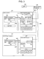
- FIG. 3 is a diagram for explaining in outline characteristic features of the present embodiment.
- the power supply units 109 and 139 are provided respectively with current monitoring units 111 and 141.
- the CPU 119 is able to periodically send a predetermined command to the current monitoring unit 111, so as to acquire the measured current values from the current monitoring unit 111 as shown by the dashed arrow 403.
- the CPU 119 is able to periodically make a request for current values to the drive I/F 155 in each additional casing 131 via the drive I/F 125 as shown by the dashed arrow 405.
- the drive I/F 155 is able to send a predetermined command to the current monitoring unit 131 in response to this request, so as to acquire current values from the current monitoring unit 131 as shown by the dashed arrow 407, and send the acquired current values to the CPU 119 as shown by the dashed arrow 405.
- the power consumption value rules are power values required for various types of processing. Specifically, examples of the power consumption value rules are the power value consumed when moving a head with a certain seek amount (e.g. within a certain head movement range), and the power value consumed at a certain disk rotational speed.
- allowed power values are stored in the memory 123.
- An allowed power value is a threshold value for a power consumption value.
- the stored allowed power values can be made to be for predetermined units.
- the predetermined units may be at least one of the storage system 107 overall and the casings. There is no limitation to this, for example other units such as drive groups may be used.
- the allowed power values for the predetermined units can be instructed from the management terminal 105 to the CPU 119 and set in the CPU 119 as shown by the dashed arrow 401.
- the management terminal 105 can acquire calculated power consumption values and so on as shown by the dashed arrow 401.
- the CPU 119 can manage the acquired current values in the memory 123. Specifically, for example, the CPU 119 can store the times of acquisition and the acquired current values for each casing separately in the memory 123.
- the CPU 119 can calculate power consumption values from the acquired current values and a predetermined voltage value (e.g. a constant voltage value applied by the power supply unit 109).
- the CPU 119 can also manage the calculated power consumption values in the memory 123. Specifically, for example, the CPU 119 can store the times of calculation and the calculated power consumption values for each casing separately in the memory 123.
- the CPU 119 can then carry out control based on the calculated power consumption values, and the allowed power values and the power consumption value rules stored in the memory 123, such that maximum performance is achieved within a range that the power consumption values do not exceed the allowed power values.
- This control may be, for example, at least one of IO processing control, cache control, and drive control.
- IO processing control is control of the IO processing according to an IO command.
- Cache control is control with regard to reading and writing data from and to the cache memory.
- Drive control is control with regard to the disk drives 127 and 157. Specifically, such control is, for example, as follows.
- control as follows may be carried out. That is, the CPU 119 may identify a required device, turn on the power supply of only the identified device, and turn off the power supply of that device when no longer needed.
- the device referred to here may be a casing, or may be a disk drive.
- the required device can be made to be a device that is to be accessed. For example, in the case of copying (e.g. backing up) data, required devices are the device having the data that is the copy source, and the device that is the copy destination.
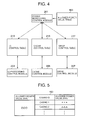
- FIG. 4 is a diagram for explaining processing carried out by the CPU 119.
- An allowed power value table 163 is stored in the memory 123.
- the allowed power value table 163 has recorded therein, for example, an allowed power value for the storage system 107 overall, and an allowed power value for each of the casings, as shown in FIG. 5.
- Computer programs executed by the CPU 119 are a power monitoring control module 201, the IO processing control module 203, a cache control module 205, and a drive controller 207.
- a power monitoring control module 201 the IO processing control module 203
- a cache control module 205 the IO processing control module 203
- a drive controller 207 the drive controller 207.
- the power monitoring control module 201 can acquire measured current values, calculate power consumption values from the acquired current values, and based on the calculated power consumption values and the allowed power value table 163, carry out at least one of IO processing control, cache control, and drive control.
- IO processing control an IO control table 213 can be referred to.
- cache control the cache control table 215 can be referred to.
- drive control a drive control table 217 can be referred to.
- the power monitoring control module 201 can carry out the control based on the table referred to. Moreover, after carrying out the control, the power monitoring control module 201 can update the table referred to.
- Each of the tables 213, 215 and 217 is, for example, a temporary table.
- the IO control table 213 has recorded therein, for example, for each IO command, at least one of an ID of the IO command, the order received from the host computer 103, an access destination address (e.g. a disk drive ID or an access destination sector number) according to the IO command, and an IO processing commencement delay time period length.
- the cache control table 215 has recorded therein, for example, at least one of a cache area ID, whether or not free, and a destaging destination address.
- the drive control table 217 has recorded therein, for example, for each disk drive, at least one of the ID of the disk drive, the ID of a drive group to which the disk drive belongs, the on/off state of the power supply of the disk drive, and the current disk rotational speed.
- the IO processing control module 203 can carry out control of processing according to an IO command from the host computer 103 based on the calculated power consumption values. At this time, the IO processing control module 203 can update the IO control table 213.
- the cache control module 205 can carry out control of reading and writing from and to the cache memory based on the calculated power consumption values. At this time, the cache control module 205 can update the cache control table 215.
- the drive control module 207 can carry out control of the disk drives based on the calculated power consumption values. At this time, the drive control module 207 can update the drive control table 217.
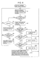
- FIG. 6 shows an example of the flow of the processing carried out by the power monitoring control module 201.
- the power monitoring control module 201 periodically acquires current values from the current monitoring units 111 and 141, and calculates power consumption values for the predetermined units from the acquired current values and the predetermined voltage (step S1).
- the predetermined units are the storage system 107 overall, and each of the casings 101 and 131.
- the power monitoring control module 201 determines whether or not each of the calculated power consumption values is not more than the allowed power value recorded in the allowed power value table 163 (S2). Here, if there is a unit for which the power consumption value is not more than the allowed power value (YES at S2), then the processing of S3 is carried out for that unit. If there is even one unit for which the power consumption value exceeds the allowed power value (NO at S2), then the processing of S7 is carried out for that unit.
- the power monitoring control module 201 determines whether or not the difference between the calculated power consumption value and the allowed power value is at least a predetermined value. If the difference is less than the predetermined value (NO at S3), then the power monitoring control module 201 carries out S1 again, whereas if the difference is at least the predetermined value (YES at 53), then the power monitoring control module 201 carries out S4.
- the power monitoring control module 201 checks on the states of the IO processing control, the cache control and the drive control (e.g. whether or not each of the IO processing control, the cache control and the drive control is being carried out). This can be done, for example, by referring to the various tables 213, 215 and 217. If, as a result, it is determined that none of these types of control is being carried out (NO at S5), then S1 is returned to, whereas if it is determined that at least one these types of control is being carried out (YES at S5), then S6 is carried out.
- the power monitoring control module 201 releases at least one of the IO processing control, the cache control and the drive control within an allowable range.
- an allowable range means that each power consumption value is not more than the allowed power value, and yet the difference between each power consumption value and the allowed power value is as small as possible. That is, this means that each power consumption value is made to be not more than the allowed power value, and yet also, as far as possible, it is made to be that the performance is not degraded.
- an example of releasing the IO processing control is shortening the delay time period for the processing carried out according to the IO command (e.g. setting this delay time period to Os) .
- An example of releasing the cache control is stopping changing the order of destaging the data in the cache memory.
- An example of releasing the drive control is setting the disk rotational speed of a disk drive rotating at a speed lower than the normal rotational speed to the normal rotational speed.
- this release of control in S6 can be carried out, for example, based on the power consumption value rules described earlier. That is, the power consumption value rules can have recorded therein, for example, the relationship between the seek amount and the power consumption value or the relationship between the disk rotational speed and the power consumption value, and it can be identified from these rules, for example, how much the power consumption value will rise if the rotational speed of a disk drive is increased from a low speed to the normal rotational speed. By releasing control based on the power consumption value rules, the performance can be increased such that each power consumption value does not exceed the allowed power value. In the case that such release of control is carried out in S6, the power monitoring control module 201 can update (e.g. delete) information relating to the control that has been released in the tables 213, 215 and 217.
- the power monitoring control module 201 can update (e.g. delete) information relating to the control that has been released in the tables 213, 215 and 217.
- the power monitoring control module 201 can carry out the same processing as in S4.
- the power monitoring control module 201 determines that the IO processing control is not being carried out (NO at S8), the power monitoring control module 201 carries out the IO processing control (S9).
- the power monitoring control module 201 determines that the IO processing control is being carried out but the cache control is not being carried out (YES at S8, NO at S10), the power monitoring control module 201 carries out the cache control (S11).
- the power monitoring control module 201 determines that the IO processing control and the cache control are being carried out but the drive control is not being carried out (YES at S10, NO at S12), the power monitoring control module 201 carries out the drive control (S13).
- the powermonitoring controller 201 determines that all of the types of control are being carried out (YES at S12), then in the case that data for which the access frequency is at least a predetermined value is stored in a disk drive 157 in an additional casing 131, the power monitoring control module 201 moves this data from that disk drive 157 to the cache memory or a disk drive 127 in the basic casing 101, and sets the disk rotational speed of the disk drive 157 from which the data was moved to a speed lower than the normal rotational speed (e.g. zero) (S14). At this time, the disk drive 127 can be made to be a disk drive as close as possible to the main controller 117.
- the normal rotational speed e.g. zero
- the above is an example of the processing carried out by the power monitoring control module 201. Note that in the above processing, determination was carried out with priority given in the order IO processing control being carried out or not, cache control being carried out or not, drive control being carried out or not, but the order of priority is not limited to this. Moreover, there may be no order of priority. However, to maintain the drive access performance in a range such that an allowed power value is not exceeded, it is thought to be necessary to maintain the disk rotational speed at a maximum, and to realize this, it is thought to be desirable to carry out the control in the above order (with the above order of priority).
- the frequency of carrying out the control can be reduced best by increasing the difference between the power consumption value and the allowed value by further reducing the rotational speed of (e.g. stopping) that drive.
- FIG. 7 shows an example of the flow of the processing carried out by the IO processing control module 203.
- This processing is, for example, commenced each time an IO command is received.
- the IO processing control module 203 Upon receiving an IO command, the IO processing control module 203 carries out queuing into a predetermined buffer (S21), and determines whether or not there is a cache hit (S22).
- a cache hit means that a cache area has been secured
- a cache hit means that read data corresponding to the read command is present in a cache area.
- the IO processing control module 203 accesses the cache memory (S23).
- the IO processing control module 203 identifies from the IO command which disk drive is to be accessed (S24). At this time, if the identified disk drive is not at the normal rotational speed (e.g. is at a low rotational speed or is in a state with the power supply off), then the IO processing control module 203 may set the disk drive to the normal rotational speed in advance.
- the IO processing control module 203 checks each power consumption value, and compares the power consumption value to the allowed power value (S25).
- the power consumption value is the value calculated by the power monitoring control module 201 and written in the memory 123.
- the IO processing control module 203 can release the IO processing control within a range such that the power consumption value does not exceed the allowed power value (S27). Whether or not the IO processing control is being carried out can be identified from the IO control table 213. When the IO processing control is released, the IO control table 213 can be updated. After that, the IO processing control module 203 accesses the disk drive identified in S24 (S28).
- the IO processing control module 203 determines whether or not delay of the IO processing is possible, and if possible (YES at S29), carries out IO processing control (S30), whereas if not possible, causes at least one of the cache control module 205 and the drive control module 207 to be carried out.
- whether or not delay of the IO processing is possible can be determined, for example, through whether the IO timeout period length for the host computer 103 (the length of the time period from the host computer 103 issuing the IO command to a predetermined response being received) is at least or less than a predetermined time period. In this case, if the IO timeout period length is at least the predetermined time period, then it can be determined that delay of the IO processing is possible.
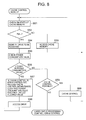
- FIG. 8 shows an example of the flow of the processing carried out by the cache control module 205.
- This processing can be carried out, for example, in the case that the state of the cache memory is monitored periodically and it is detected that the cache memory is full, or in the case of controlling the order of writing to drives. In the case of the former, the processing can be commenced from S54, described below.
- the cache control module 205 checks on the state of the cache memory (S51).
- the cache control module 205 accesses the free cache area (S53).
- the cache control module 205 identifies the disk drive that is to be accessed (S54), and compares each calculated power consumption value with the allowed power value (S55).
- the cache control module 205 can release the cache control within a range such that the power consumption value does not exceed the allowed power value (S57). Whether or not the cache control is being carried out can be identified from the cache control table 215. When the cache control is released, the cache control table 215 can be updated. After that, the cache control module 205 accesses the disk drive identified in S54 (S58).
- the cache control module 205 determines whether or not cache control is possible, and if possible (YES at S59), carries out the cache control (S60), whereas if not possible, causes at least one of the IO processing control module 203 and the drive control module 207 to be carried out.
- whether or not the cache control is possible can be determined, for example, through whether or not the power values can be adjusted by changing the order of destaging data in the cache memory. This determination can be carried out, for example, from the results of simulation using a predetermined algorithm.
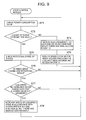
- FIG. 9 shows an example of the flow of the processing carried out by the drive control module 207.
- This processing can be carried out, for example, in the case that it is necessary to reduce a power consumption value to not more than a predetermined value, or in the case that a power consumption value cannot be made to be not more than the allowed power value through the IO processing control or the cache control.
- the drive control module 207 compares each calculated power consumption value with the allowed power value (S71).
- the drive control module 207 checks the access frequency for each disk drive and whether or not there has been access recently, and reduces the disk rotational speed of a disk drive for which the access frequency is not more than a predetermined value and there has been no access recently (S74). Whether or not there has been access recently can be identified, for example, by the drive control module 207 recording the most recent access time for each of the disk drives in the drive control table 217. "No access recently" means that the most recent access time and the current time are separated by at least a predetermined value.
- the drive control module 207 checks the current disk rotational speed of each of the disk drives by referring to the drive control table 217.
- the drive control module 207 determines from the power consumption value, the allowed power value and the power consumption value rules whether or not the disk rotational speed can be increased within a range such that the power consumption value does not exceed the allowed power value (S77). In the case that the result is that it is determined that this can be done (YES at S77), the drive control module 207 issues an instruction to a low-speed disk drive to increase the disk rotational speed, this being in accordance with the access frequency and whether or not there has been access recently (S78). In this step S78, out of low-speed disk drives, the disk drive for which the access frequency is highest and/or the most recent access time is shortest is increased in speed.
- the increasing in speed refers, for example, to setting to a rotational speed at least faster than the current disk rotational speed, and specifically means, for example, setting to the normal rotational speed or a rotational speed close thereto.
- "low-speed" includes the rotational speed being zero, i.e. the disk drive being stopped.
- FIG. 10 shows an example of the logical configuration of the management terminal 105.
- the management module 251 is a computer program for carrying out management of the storage system 107, and has therein an allowed power value setting module 253, a power consumption value management module 255, and IO performance management module 257, and a display control module 258.
- the allowed power value setting module 253 is a program module for setting the allowed power values into the storage system 107.
- the allowed power value setting module 253, for example, displays a GUI (graphical user interface), and receives the allowed power values from an administrator via the GUI.
- the administrator can input the allowed power values with importance attached to either power saving or performance.
- the allowed power value setting module 253 sends the allowed power values inputted from the administrator to the storage system 107.
- the allowed power value table 163 is stored in the memory 123 in the basic casing 101.
- the allowed power values can be received for predetermined units (the storage system and each of the casings).
- the allowed power value setting module 253 can store a table 259 showing the received allowed power values (see FIG.
- the allowed power value setting module 253 can receive allowed power values for each time period separately or for each usage separately, and can set the allowed power values in the storage system 107 for each time period separately or for each usage separately.
- “for each time period separately” indicates referring to what allowed power value for what time period.
- “for each usage separately” indicates referring to what allowed power value in the case of what usage (e.g. copying between casings, or copying within a casing).
- the CPU 119 in the basic casing 101 can refer to the allowed power values in accordance with the current time or the processing being carried out (the usage).
- the IO performance management module 257 acquires IO performance from the storage system 107, and stores the acquired IO performance in the storage resource in the management terminal 105.
- the "IO performance” indicates the history of the number of IO processing instances (e.g. the number of IO processing instances in each time period).
- the IO processing control module 203 of the storage system can record the history of the number of IO processing instances in the memory 123.
- the power consumption value management module 255 acquires the calculated power consumption values at each time from the storage system 107, and stores the acquired power consumption values for each time in the storage resource in the management terminal 105.
- the display control module 258 can identify the highest value and the lowest value out of the current power consumption values or the power consumption values up to now from the storage resource, and display the identified values.
- the power consumption value management module 255 can display the relationship between the IO performance and the power consumption values at each time. Specifically, for example, the power consumption value management module 255 can display superimposed on one another in the same display area (e.g. an area having the same vertical axis and horizontal axis) a graph showing changes in the number of IO processing instances by time period, and a graph showing changes in the power consumption values by time period. As a result, the administrator can grasp at a glance the relationship between the IO performance and the power consumption values.
- each of the IO processing control, the cache control, and the drive control is released within a range such that a power consumption value does not exceed an allowed power value. As a result, both power saving and good performance can be achieved.
- FIG. 12 there are a plurality of drive groups A to D in one casing, and the disk rotational speed is controlled taking each drive group as a unit.
- the numbers in brackets are the rotational speed, i.e. the number of rotations per unit time.
- the drive group A is at the normal rotational speed, and the other groups are at a low speed.
- drive group C is at the highest speed (taken as low rotational speed 1)
- drive group D is at the next highest speed (taken as low rotational speed 2)
- drive group B is at the lowest speed (stopped).
- FIG. 13 shows drive groups A and B being in a first casing, and drive groups C and D being in a second casing. That is, in this first variation, the plurality of drive groups to be controlled may be in a single drive group, or may be in a plurality of casings.
- At least one of the power monitoring control module 201 and the drive control module 207 (in the following the power monitoring control module 201 is taken as an example) is able to carry out the following processing.
- the power monitoring control module 201 checks the access frequency and the most recent access time for each of the drive groups A, B, C and D. Moreover, the power monitoring control module 201 calculates, based on the power consumption value rules, how much the disk rotational speeds can be increased overall to increase the power consumption value within the range of the allowed power value and thus improve the performance. The power monitoring control module 201 then allots the calculated disk rotational speeds to the drive groups.
- the power monitoring control module 201 increases the disk rotational speed for drive group B (e.g. sets this disk rotational speed to low rotational speed 1, low rotational speed 2, or the normal rotational speed). Moreover, for example, in the case that there is to be access to drive group C, the power monitoring control module 201 increases the disk rotational speed for drive group C (e.g. sets this disk rotational speed to the normal rotational speed). Moreover, for example, in the case that there is to be access to drive group D, the power monitoring control module 201 increases the disk rotational speed for drive group D (e.g. sets this disk rotational speed to low rotational speed 1 or the normal rotational speed).
- the power monitoring control module 201 can set any of drive groups B to D to the normal rotational speed depending on the difference between the power consumption value and the allowed power value. Moreover, in the case that data in drive group B, C or D is moved to drive group A, and the disk from which the data was moved is set to the normal rotational speed, the power monitoring control module 201 can return this data from drive group A to another one of drive groups B, C and D.
- FIG. 14 shows an example of processing carried out in a second variation of the embodiment of the present invention.
- This processing is a variation of the processing carried out by the IO control module (this term is also sometimes used in the other variations), which includes the IO processing control module 203, the cache control module 205 and the drive control module 207.
- the IO command is a read command is taken as an example, but application is also possible in the case that a write command.
- the IO control module analyzes the IO command from the host computer 103 (S101), and identifies where the read data corresponding to the IO command is (S102).
- the IO control module compares a calculated power consumption value with the allowed power value, and if there is leeway in the power consumption value relative to the allowed power value (YES at S103), determines whether or not the read data is in the cache memory or a disk drive rotating at the normal rotational speed (S104), and if so (YES at S104), reads out the read data therefrom (S105). Otherwise (NO at S104), the IO control module checks the rotational speed of the disk drive in which the read data is stored (S115), and if this rotational speed is low, determines whether or not the power consumption value will still not exceed the allowed power value even if the rotational speed is increased (S116).
- the IO control module determines whether or not a predicted power consumption value increased due to the rotational speed being increased (this predicted power consumption value is, for example, the value obtained by adding, to the power consumption value before the rotational speed is increased, the increase in the power consumption value due to the rotational speed being increased) still does not exceed the allowed power value. In the case that it is determined that the predicted power consumption value does not exceed the allowed power value, the IO control module returns the disk drive to the normal rotational speed, and then acquires the read data from the disk drive (S117).
- this predicted power consumption value is, for example, the value obtained by adding, to the power consumption value before the rotational speed is increased, the increase in the power consumption value due to the rotational speed being increased
- the IO control module determines whether or not delay of IO processing is possible, and if determined to be impossible (NO at S107), determines whether or not cache control is possible (S109), and if determined to be possible (YES at S109), carries out the cache control (S110). If the cache control is determined in S109 to be impossible (NO at S109), then S112 is carried out.
- the IO control module reduces the rotational speeds of all of the disk drives for which the access frequency is low and there has been no access recently (S112), and if as a result leeway arises in the power consumption value with regard to the allowed power range (YES at S113), then the IO control module increases, within a range such that the power consumption value does not exceed the allowed power value, the disk rotational speed of a disk drive whose speed has been reduced, this being in accordance with the access frequency and whether or not there has been access recently (S114).
- drive groups A and B in the basic casing 101 are made to be at the normal rotational speed, and drive groups C and D in an additional casing 131 are made to be at low speed.
- control is carried out as follows.
- the IO control module checks on the state of the cache memory and the rotational speed of the disk drive in drive group C.
- the IO control module temporarily stores the write data in the drive group A or B which is at the normal rotational speed, and sends a completion report to the host computer 103.
- the IO control module When the IO control module detects that the drive group C has started up (reached the normal rotational speed), the IO control module reads the temporarily stored data out from the drive group A or B, and writes the read out data to the started up drive group C.
- the above is an example of the control in the case that a low-speed drive is accessed.
- cache destaging control can be carried out as follows.
- the IO control module identifies that the cache memory is full, of the data present in the cache memory, the IO control module identifies data that has a low access frequency (e.g. an access frequency not more than a predetermined value) and is old (e.g. an update time is at least a predetermined time period before the current time), and determines the storage locations (destaging destinations) for the identified data. This can be done, for example, by referring to the cache control table 215.
- a low access frequency e.g. an access frequency not more than a predetermined value
- an update time is at least a predetermined time period before the current time
- the IO control module checks on the rotational speed for each of the drive groups A and D. As a result, the IO control module gives priority to storing data in the drive group having the faster rotational speed, for example drive group A which is at the normal rotational speed. That is, the IO control module gives priority to destaging the data for which the drive group A is the storage location.
- the IO control module compares a power consumption value with the allowed power value, and if there is leeway in the power consumption value relative to the allowed power value, may control the rotational speed for the drive group D to the normal rotational speed before data has finished being destaged to the drive group A, and then destage data to the drive group D after the destaging of data to the drive group A has been completed. Moreover, the IO control module may temporarily destage the data for the drive group D to the drive group A, and then subsequently (e.g. after the rotational speed for the drive group D has become the normal rotational speed) move the data from the drive group A to the drive group D.
- the IO control module can carry out control optimizing the data access order.
- various processing can be carried out upon storage system startup, upon a casing and/or disk drive being added and/or removed, and upon a disk drive being blocked.
- FIG. 16 shows an example of the flow of processing carried out upon storage system startup.
- the power monitoring control module 201 acquires current values from the current monitoring units 111 and 141 (S201).
- the power monitoring control module 201 determines, for each of the basic casing 101 and the additional casings 131, the number of disk drives installed and whether or not the rotational speeds of the disk drives can be controlled (S202).
- the number of disk drives installed can be determined, for example, according to whether or not there is a response upon sending a signal to each port to which a disk drive may be connected.
- Whether or not the rotational speed of a disk drive can be controlled can be determined, for example, from disk drive attributes (e.g. the disk drive vendor, type, etc.) obtained by sending an inquiry to the disk drive and receiving the disk drive attributes as a response.
- disk drive attributes e.g. the disk drive vendor, type, etc.
- the disk drive attributes may contain information indicating whether or not the rotational speed can be controlled, or in the case that such information is not contained, whether or not the rotational speed can be controlled may be determined by referring to a table in which are recorded the attributes of disk drives for which the rotational speed can be controlled, the determination being carried out based on the table and the received disk drive attributes.
- the power monitoring control module 201 In the case that the power monitoring control module 201 identifies a disk drive for which the rotational speed can be controlled, the power monitoring control module 201 instructs this disk drive to rotate at a certain rotational speed, and monitors the current value (S203). That is, the power monitoring control module 201 monitors the change in the current value due to the disk drive rotating at the instructed rotational speed.
- the power monitoring control module 201 issues a dummy access instruction to the disk drive, and monitors the current value (S204).
- This access instruction is an instruction specifying an access range, in other words an access instruction specifying the seek amount for the disk drive to be a certain amount. That is, the power monitoring control module 201 monitors the change in the current value due to seeking with the instructed seek amount.
- the power monitoring control module 201 is able to store the identified current value changes in the memory 123 as parameters separately for the rotational speed and the seek amount (S205).
- the power monitoring control module 201 is able to calculate the power consumption values corresponding to the rotational speed and the seek amount by multiplying the current value changes by the voltage value, and is able to store the calculated power consumption values in the memory 123 as power consumption value rules.
- FIG. 17 shows an example of the flow of processing carried out upon installing an additional disk drive.
- the power monitoring control module 201 acquires information on an added disk drive by sending a predetermined inquiry to that disk drive, and acquires the increase in the current value due to the addition of the disk drive by calculating the difference between the current value immediately before the addition and the current value acquired immediately after the addition (S251).
- the power monitoring control module 201 calculates the power consumption value at the present time before starting up the added disk drive, and based on this power consumption value and the allowed power value, carries out control to optimize both power saving and performance, i.e. carries out IO processing control or release thereof, cache control or release thereof, and/or drive control or release thereof (S252).
- the power monitoring control module 201 starts up the added disk drive (S253), and acquires the increase in the current value due to the startup of the added disk drive by calculating the difference between the current value immediately before the startup and the current value acquired immediately after the startup (S254). Note that this step S254 can be carried out, for example, to acquire the current value in a state in which the disk drive has actually been started up. Likewise for S304, described below.
- FIG. 18 shows an example of the flow of processing carried out upon installing an additional casing having disk drives installed therein.
- the power monitoring control module 201 acquires information on disk drives in the added additional casing by sending a predetermined inquiry to those disk drives, and acquires the increase in the current value due to the addition of the additional casing by calculating the difference between the current value immediately before the addition and the current value acquired immediately after the addition (5301).
- the power monitoring control module 201 calculates the power consumption value at the present time before starting up the disk drives in the added additional casing, and based on this power consumption value and the allowed power value, carries out control to optimize both power saving and performance, i.e. carries out IO processing control or release thereof, cache control or release thereof, and/or drive control or release thereof (S302).
- the power monitoring control module 201 starts up the disk drives in the additional casing (S303), and acquires the increase in the current value due to the startup of the disk drives in the additional casing by calculating the difference between the current value immediately before the startup and the current value acquired immediately after the startup (S304).
- FIG. 19 shows an example of the flow of processing carried out upon removing a disk drive.
- the power monitoring control module 201 acquires information on a removed disk drive by sending a predetermined inquiry to that disk drive, and acquires a current value after the removal from at least the current monitoring unit in the casing from which the disk drive was removed (5351).
- the power monitoring control module 201 calculates the power consumption value after the removal from the acquired current value, and shares out the difference between the power consumption value after the removal and the power consumption value before the removal (S352). That is, based on the power consumption value after the removal and the allowed power value, the power monitoring control module 201 carries out control to optimize both power saving and performance, i.e. carries out IO processing control or release thereof, cache control or release thereof, and/or drive control or release thereof.
- FIG. 20 shows an example of the flow of processing carried out upon blocking a disk drive.
- the power monitoring control module 201 acquires information on the blocked disk drive, and acquires a current value from at least the current monitoring unit in the casing having the blocked disk drive therein (S401).
- the power monitoring control module 201 gathers required information, and stops the rotation of the blocked disk drive (S402).
- the required information is, for example, information relating to problems relating to the blocking of the disk drive.
- the rotation is stopped when a disk drive is blocked.
- "block” means to put into a non-operating state, and this is not related to whether or not the disk is rotating.
- the power monitoring control module 201 calculates the power consumption value for the casing having the blocked disk drive therein, and shares out the difference between the power consumption value after the blocking and the power consumption value before the blocking (S403). That is, based on the power consumption value after the blocking and the allowed power value, the power monitoring control module 201 carries out control to optimize both power saving and performance, i.e. carries out IO processing control or release thereof, cache control or release thereof, and/or drive control or release thereof.
- each of the disk drives 127 and 157 may instead be another type of storage device such as a flash memory.
- a flash memory for example, in the case of a flash memory, commencing rotation and stopping rotation should be read instead as turning on the power supply and turning off the power supply.
- the main controller 117 may comprise at least one first control circuit board that controls communication with a host device (e.g. a host computer or another storage system), at least one second control circuit board that controls communication with storage devices, a cache memory that can store data to be transferred between the host device and the storage devices, a control memory that can store data for controlling the storage system 107, and a connecting unit (e.g. a switch such as a crossbar switch) that connects the first control circuit board, the second control circuit board, the cache memory and the control memory.
- a connecting unit e.g. a switch such as a crossbar switch
- Each control circuit board may be provided with at least one microprocessor.
- one of the first control circuit board and the second control circuit board may carry out processing as the main controller 117, or both may do so in collaboration.
- the control memory may be omitted, in which case an area for storing information that would have been stored in the control memory may be provided in the cache memory.
- each casing there may be provided a voltage monitoring unit that measures the voltage applied to the loads from the power supply unit.
- the power monitoring control module 201 may acquire the measured voltage value from the voltage monitoring unit in each casing, and calculate the power consumption value by multiplying the acquired voltage value by the current value acquired from the current monitoring unit.
- the control described above may be carried out using current values, without calculating power consumption values.
- control of a fan e.g. power supply on/off or rotational speed
- control of other loads may also be carried out based on the power consumption values and the allowed power values.
Landscapes
- Engineering & Computer Science (AREA)
- Theoretical Computer Science (AREA)
- Physics & Mathematics (AREA)
- General Engineering & Computer Science (AREA)
- General Physics & Mathematics (AREA)
- Human Computer Interaction (AREA)
- Power Sources (AREA)
- Direct Current Feeding And Distribution (AREA)
- Supply And Distribution Of Alternating Current (AREA)
Applications Claiming Priority (1)
| Application Number | Priority Date | Filing Date | Title |
|---|---|---|---|
| JP2006170563A JP4794370B2 (ja) | 2006-06-20 | 2006-06-20 | 省電力とパフォーマンスを両立したストレージシステム及び記憶制御方法 |
Publications (2)
| Publication Number | Publication Date |
|---|---|
| EP1870796A2 true EP1870796A2 (de) | 2007-12-26 |
| EP1870796A3 EP1870796A3 (de) | 2012-05-30 |
Family
ID=37511789
Family Applications (1)
| Application Number | Title | Priority Date | Filing Date |
|---|---|---|---|
| EP06255775A Withdrawn EP1870796A3 (de) | 2006-06-20 | 2006-11-10 | Speichersystem und Speichersteuerverfahren zum Erreichen von sowohl Energieeinsparung als guter Leistungsfähigkeit |
Country Status (3)
| Country | Link |
|---|---|
| US (1) | US7543108B2 (de) |
| EP (1) | EP1870796A3 (de) |
| JP (1) | JP4794370B2 (de) |
Cited By (1)
| Publication number | Priority date | Publication date | Assignee | Title |
|---|---|---|---|---|
| EP3377978A4 (de) * | 2016-01-13 | 2019-06-05 | Hewlett-Packard Enterprise Development LP | Restrukturierte ein-/ausgabeanforderungen |
Families Citing this family (45)
| Publication number | Priority date | Publication date | Assignee | Title |
|---|---|---|---|---|
| GB0616375D0 (en) * | 2006-08-17 | 2006-09-27 | Ibm | An apparatus for facilitating disaster recovery |
| JP5008955B2 (ja) | 2006-11-28 | 2012-08-22 | 株式会社日立製作所 | 節電機能を備えたストレージシステム |
| US8166315B1 (en) * | 2007-03-23 | 2012-04-24 | Emc Corporation | Method for calculating power for data storage systems |
| US8140754B2 (en) * | 2008-01-03 | 2012-03-20 | Hitachi, Ltd. | Methods and apparatus for managing HDD's spin-down and spin-up in tiered storage systems |
| JP5141278B2 (ja) * | 2008-02-08 | 2013-02-13 | 日本電気株式会社 | ディスクアレイシステム,ディスクアレイ制御方法及びディスクアレイ制御用プログラム |
| JP5288899B2 (ja) * | 2008-06-20 | 2013-09-11 | 株式会社日立製作所 | 消費電力推定を行うストレージ装置及びストレージ装置の電力推定方法 |
| US20100030791A1 (en) * | 2008-07-30 | 2010-02-04 | Diomede Corporation | Systems and methods for power aware data storage |
| JP2010055152A (ja) * | 2008-08-26 | 2010-03-11 | Hitachi Ltd | 記憶制御装置 |
| JP2010055287A (ja) * | 2008-08-27 | 2010-03-11 | Hitachi Ltd | 節電機能を備えたストレージシステム |
| US8001405B2 (en) * | 2008-08-29 | 2011-08-16 | International Business Machines Corporation | Self-tuning power management techniques |
| JP4920658B2 (ja) | 2008-10-20 | 2012-04-18 | 株式会社日立製作所 | 電力推定方法及び計算機システム |
| US7983125B2 (en) * | 2008-10-27 | 2011-07-19 | Lsi Corporation | Table-driven power utilization metrics |
| JP2010128985A (ja) * | 2008-11-28 | 2010-06-10 | Hitachi Ltd | ストレージ管理サーバ、ストレージ構成の再配置方法 |
| JP5412902B2 (ja) * | 2009-03-17 | 2014-02-12 | 日本電気株式会社 | ストレージシステム |
| US8285948B2 (en) * | 2009-03-23 | 2012-10-09 | International Business Machines Corporation | Reducing storage system power consumption in a remote copy configuration |
| WO2010122596A1 (en) * | 2009-04-21 | 2010-10-28 | Hitachi, Ltd. | Storage system, control methods for the same and programs |
| JP2010282422A (ja) * | 2009-06-04 | 2010-12-16 | Toshiba Corp | データ記憶装置及びデータ転送制御方法 |
| US8468375B2 (en) * | 2009-07-15 | 2013-06-18 | Hitachi, Ltd. | Energy consumption management for storage system using upper limit value during predetermined period |
| JP5209591B2 (ja) * | 2009-11-16 | 2013-06-12 | 株式会社日立製作所 | 省電力機能を有するストレージシステム |
| JP5397777B2 (ja) * | 2010-04-01 | 2014-01-22 | 日本電気株式会社 | ストレージ装置、及び、電力制御方法 |
| JP5585235B2 (ja) * | 2010-06-21 | 2014-09-10 | 富士通株式会社 | ストレージ制御装置、ストレージ制御方法、ストレージシステム |
| EP2674851B1 (de) * | 2011-02-10 | 2018-01-17 | Fujitsu Limited | Speichersteuerungsvorrichtung, speichervorrichtung, speichersystem, speichersteuerungsverfahren und programm dafür |
| JP5382466B2 (ja) * | 2011-03-31 | 2014-01-08 | 日本電気株式会社 | ストレージ装置及びストレージ装置のデータ書き込み制御方法 |
| US8788742B2 (en) * | 2011-05-23 | 2014-07-22 | International Business Machines Corporation | Using an attribute of a write request to determine where to cache data in a storage system having multiple caches including non-volatile storage cache in a sequential access storage device |
| US8745369B2 (en) * | 2011-06-24 | 2014-06-03 | SanDisk Technologies, Inc. | Method and memory system for managing power based on semaphores and timers |
| US8694719B2 (en) | 2011-06-24 | 2014-04-08 | Sandisk Technologies Inc. | Controller, storage device, and method for power throttling memory operations |
| CN103065690A (zh) * | 2011-10-19 | 2013-04-24 | 鸿富锦精密工业(深圳)有限公司 | 降低存储系统启动电流的系统及方法 |
| JP5998677B2 (ja) | 2012-06-29 | 2016-09-28 | 富士通株式会社 | ストレージ装置および接続装置 |
| US9430014B2 (en) * | 2013-07-18 | 2016-08-30 | Qualcomm Incorporated | System and method for idle state optimization in a multi-processor system on a chip |
| US20150033045A1 (en) * | 2013-07-23 | 2015-01-29 | Apple Inc. | Power Supply Droop Reduction Using Feed Forward Current Control |
| US9947386B2 (en) * | 2014-09-21 | 2018-04-17 | Advanced Micro Devices, Inc. | Thermal aware data placement and compute dispatch in a memory system |
| US10146293B2 (en) * | 2014-09-22 | 2018-12-04 | Western Digital Technologies, Inc. | Performance-aware power capping control of data storage devices |
| US9541988B2 (en) * | 2014-09-22 | 2017-01-10 | Western Digital Technologies, Inc. | Data storage devices with performance-aware power capping |
| JP6464874B2 (ja) * | 2015-03-27 | 2019-02-06 | 富士通株式会社 | ストレージ制御装置,ストレージ装置およびストレージ制御プログラム |
| US9965206B2 (en) | 2015-10-23 | 2018-05-08 | Western Digital Technologies, Inc. | Enhanced queue management for power control of data storage device |
| US10956322B2 (en) * | 2016-06-02 | 2021-03-23 | International Business Machines Corporation | Storage drive dependent track removal in a cache for storage |
| JP2018101322A (ja) * | 2016-12-21 | 2018-06-28 | 日本電気株式会社 | ストレージアレイ装置、消費電力調整方法、および消費電力調整プログラム |
| US10020046B1 (en) | 2017-03-03 | 2018-07-10 | Micron Technology, Inc. | Stack refresh control for memory device |
| KR102430209B1 (ko) | 2017-09-07 | 2022-08-05 | 삼성전자주식회사 | 저장 장치 및 저장 장치에 포함된 컨트롤러들 |
| KR102615227B1 (ko) * | 2018-02-01 | 2023-12-18 | 에스케이하이닉스 주식회사 | 메모리 시스템 및 그것의 동작 방법 |
| JP7048895B2 (ja) * | 2018-08-23 | 2022-04-06 | 富士通株式会社 | 制御装置および制御プログラム |
| JP6978087B2 (ja) * | 2019-03-26 | 2021-12-08 | Necプラットフォームズ株式会社 | ストレージ制御装置、制御方法及びプログラム |
| US12050497B2 (en) | 2022-01-14 | 2024-07-30 | Samsung Electronics Co., Ltd. | Systems and methods for power relaxation on startup |
| US12079101B2 (en) * | 2022-04-22 | 2024-09-03 | EMC IP Holding Company, LLC | System and method for modeling and forecasting input/output (IO) performance using adaptable machine learning |
| US12613819B2 (en) * | 2024-05-15 | 2026-04-28 | International Business Machines Corporation | System steering for an I/O sustainability target |
Family Cites Families (12)
| Publication number | Priority date | Publication date | Assignee | Title |
|---|---|---|---|---|
| JPH0242549A (ja) * | 1988-08-03 | 1990-02-13 | Hitachi Ltd | ライトアフタ型デイスクキヤツシユ制御装置 |
| JP3580630B2 (ja) * | 1996-02-26 | 2004-10-27 | インターナショナル・ビジネス・マシーンズ・コーポレーション | 消費電力を管理するシステム及び電源を管理する方法 |
| JP2000149383A (ja) | 1998-11-13 | 2000-05-30 | Nec Eng Ltd | ディスク記憶装置及びそれに用いるスピンドル起動制御方法並びにその制御プログラムを記録した記録媒体 |
| JP4325817B2 (ja) * | 1999-04-05 | 2009-09-02 | 株式会社日立製作所 | ディスクアレイ装置 |
| JP4091225B2 (ja) * | 1999-11-19 | 2008-05-28 | 富士通株式会社 | ディスク・タイムシェアリング装置及び方法 |
| JP2002042412A (ja) * | 2000-07-26 | 2002-02-08 | Matsushita Electric Ind Co Ltd | 記録再生装置 |
| JP2002343012A (ja) * | 2001-05-18 | 2002-11-29 | Sanyo Electric Co Ltd | ディスクドライブ装置 |
| JP4972845B2 (ja) * | 2001-09-27 | 2012-07-11 | 富士通株式会社 | ストレージシステム |
| JP2003263249A (ja) * | 2002-03-11 | 2003-09-19 | Yamaha Corp | 電力供給管理装置及び省電力モードを有するシステム |
| JP2003308176A (ja) * | 2002-04-03 | 2003-10-31 | Internatl Business Mach Corp <Ibm> | データ記憶装置、コマンド・キューのリオーダリング方法、データ処理方法およびプログラム |
| KR20040081301A (ko) * | 2003-03-10 | 2004-09-21 | 마츠시타 덴끼 산교 가부시키가이샤 | 전력 절약 연산 장치 및 그 방법, 및 전력 절약 연산프로그램 및 그 프로그램 제품 |
| US20050210304A1 (en) * | 2003-06-26 | 2005-09-22 | Copan Systems | Method and apparatus for power-efficient high-capacity scalable storage system |
-
2006
- 2006-06-20 JP JP2006170563A patent/JP4794370B2/ja not_active Expired - Fee Related
- 2006-08-08 US US11/500,436 patent/US7543108B2/en not_active Expired - Fee Related
- 2006-11-10 EP EP06255775A patent/EP1870796A3/de not_active Withdrawn
Cited By (1)
| Publication number | Priority date | Publication date | Assignee | Title |
|---|---|---|---|---|
| EP3377978A4 (de) * | 2016-01-13 | 2019-06-05 | Hewlett-Packard Enterprise Development LP | Restrukturierte ein-/ausgabeanforderungen |
Also Published As
| Publication number | Publication date |
|---|---|
| US7543108B2 (en) | 2009-06-02 |
| JP2008003719A (ja) | 2008-01-10 |
| JP4794370B2 (ja) | 2011-10-19 |
| EP1870796A3 (de) | 2012-05-30 |
| US20070294552A1 (en) | 2007-12-20 |
Similar Documents
| Publication | Publication Date | Title |
|---|---|---|
| US7543108B2 (en) | Storage system and storage control method achieving both power saving and good performance | |
| EP1605456B1 (de) | Modul zur Verminderung der Leistungsaufnahme eines Festplattenlaufwerks | |
| EP3242185B1 (de) | Serverrackleistungsverwaltung | |
| US7702848B2 (en) | Adaptive storage system including hard disk drive with flash interface | |
| US20040015731A1 (en) | Intelligent data management fo hard disk drive | |
| EP2049968B1 (de) | Adaptives speichersystem mit einem festplattenlaufwerk mit flash-schnittstelle | |
| EP1605361B1 (de) | Cachespeicher-Hierarchie | |
| CN101114492B (zh) | 带有非易失性存储器的、具有多种操作模式的盘驱动器 | |
| US8356139B2 (en) | Storage system for maintaining hard disk reliability | |
| EP1959334A2 (de) | Speichersteuerungsvorrichtung | |
| US20080005461A1 (en) | Power-saving control apparatus, power-saving control method, and computer product | |
| US20070136522A1 (en) | Information processing apparatus, media player and method for controlling a storage device | |
| JP5353732B2 (ja) | ストレージ管理装置、ストレージシステム、ストレージ管理プログラム、ストレージ管理方法 | |
| US20110185201A1 (en) | Storage system and its power control method | |
| CN106250051A (zh) | 磁盘驱动器速度管理方法与系统 | |
| US10635154B2 (en) | Intelligent SAS phy power management | |
| CN117076170A (zh) | 硬盘数据处理方法、装置、计算机设备及存储介质 | |
| JP2014238771A (ja) | ストレージ制御装置、アクセス制御方法、及び制御プログラム | |
| WO2007085978A2 (en) | A method of controlling a page cache memory in real time stream and best effort applications | |
| JP2005293416A (ja) | 仮想ライブラリ装置におけるロードバランス方法 |
Legal Events
| Date | Code | Title | Description |
|---|---|---|---|
| PUAI | Public reference made under article 153(3) epc to a published international application that has entered the european phase |
Free format text: ORIGINAL CODE: 0009012 |
|
| 17P | Request for examination filed |
Effective date: 20061129 |
|
| AK | Designated contracting states |
Kind code of ref document: A2 Designated state(s): AT BE BG CH CY CZ DE DK EE ES FI FR GB GR HU IE IS IT LI LT LU LV MC NL PL PT RO SE SI SK TR |
|
| AX | Request for extension of the european patent |
Extension state: AL BA HR MK YU |
|
| PUAL | Search report despatched |
Free format text: ORIGINAL CODE: 0009013 |
|
| AK | Designated contracting states |
Kind code of ref document: A3 Designated state(s): AT BE BG CH CY CZ DE DK EE ES FI FR GB GR HU IE IS IT LI LT LU LV MC NL PL PT RO SE SI SK TR |
|
| AX | Request for extension of the european patent |
Extension state: AL BA HR MK RS |
|
| RIC1 | Information provided on ipc code assigned before grant |
Ipc: G06F 3/06 20060101ALI20120423BHEP Ipc: G06F 1/32 20060101AFI20120423BHEP |
|
| STAA | Information on the status of an ep patent application or granted ep patent |
Free format text: STATUS: THE APPLICATION HAS BEEN WITHDRAWN |
|
| 18W | Application withdrawn |
Effective date: 20120710 |