EP1871002A2 - Mécanisme de déplacement destiné au réglage d'au moins deux pièces mobiles dans un véhicule automobile - Google Patents
Mécanisme de déplacement destiné au réglage d'au moins deux pièces mobiles dans un véhicule automobile Download PDFInfo
- Publication number
- EP1871002A2 EP1871002A2 EP20070106895 EP07106895A EP1871002A2 EP 1871002 A2 EP1871002 A2 EP 1871002A2 EP 20070106895 EP20070106895 EP 20070106895 EP 07106895 A EP07106895 A EP 07106895A EP 1871002 A2 EP1871002 A2 EP 1871002A2
- Authority
- EP
- European Patent Office
- Prior art keywords
- adjusting drive
- motor
- drive
- adjusting
- control electronics
- Prior art date
- Legal status (The legal status is an assumption and is not a legal conclusion. Google has not performed a legal analysis and makes no representation as to the accuracy of the status listed.)
- Withdrawn
Links
Images

Classifications
-
- G—PHYSICS
- G05—CONTROLLING; REGULATING
- G05B—CONTROL OR REGULATING SYSTEMS IN GENERAL; FUNCTIONAL ELEMENTS OF SUCH SYSTEMS; MONITORING OR TESTING ARRANGEMENTS FOR SUCH SYSTEMS OR ELEMENTS
- G05B19/00—Program-control systems
- G05B19/02—Program-control systems electric
- G05B19/18—Numerical control [NC], i.e. automatically operating machines, in particular machine tools, e.g. in a manufacturing environment, so as to execute positioning, movement or co-ordinated operations by means of program data in numerical form
- G05B19/19—Numerical control [NC], i.e. automatically operating machines, in particular machine tools, e.g. in a manufacturing environment, so as to execute positioning, movement or co-ordinated operations by means of program data in numerical form characterised by positioning or contouring control systems, e.g. to control position from one programmed point to another or to control movement along a programmed continuous path
-
- G—PHYSICS
- G05—CONTROLLING; REGULATING
- G05B—CONTROL OR REGULATING SYSTEMS IN GENERAL; FUNCTIONAL ELEMENTS OF SUCH SYSTEMS; MONITORING OR TESTING ARRANGEMENTS FOR SUCH SYSTEMS OR ELEMENTS
- G05B2219/00—Program-control systems
- G05B2219/30—Nc systems
- G05B2219/37—Measurements
- G05B2219/37094—Hall sensor
-
- G—PHYSICS
- G05—CONTROLLING; REGULATING
- G05B—CONTROL OR REGULATING SYSTEMS IN GENERAL; FUNCTIONAL ELEMENTS OF SUCH SYSTEMS; MONITORING OR TESTING ARRANGEMENTS FOR SUCH SYSTEMS OR ELEMENTS
- G05B2219/00—Program-control systems
- G05B2219/30—Nc systems
- G05B2219/45—Nc applications
- G05B2219/45018—Car, auto, vehicle
Definitions
- the invention relates to an adjusting drive for adjusting at least one movable part in a motor vehicle and an adjusting actuator having air flap plate.
- adjusting drives consisting of a DC motor and a reduction gear, for the adjustment of moving parts, such as seats, sunroofs, windows or air distribution flaps an air conditioner used.
- the control of the position and the displacement speed of the movable part are accomplished by means of various electronic circuits and circuits for power supply and position detection.
- An air damper in which a microcomputer and an electronic control unit are integrated in a common control device in order to reduce the number of cable connections required between the damper and the control device and the production costs and costs.
- the control device comprises a data interface for transmitting the rotational speed of an electric motor integrated in the air flap actuator and a control signal generated by the microcomputer for power electronics for controlling the electric motor.
- a position correction circuit for controlling the position is provided to correct errors caused by over-rotation of the electric motor or by an adjustment of the Lucasklappenstellers.
- control device has a protective circuit intended to prevent destruction of the air damper actuator by excess temperatures due to excessive currents, overload or short circuit between the air damper actuator and the control device.
- control device includes the aforementioned power electronics for driving the electric motor and a breaker circuit which cooperates with the position correction circuit.
- the control device and the air damper plate are connected to each other via a two-wire line with a length of one to five meters.
- the adjusting drive according to the invention for adjusting a movable part in a motor vehicle comprises at least one output element for adjusting the movable part, a DC motor, in particular a DC collector motor, for driving the output element via a motor shaft, control electronics for driving the DC motor, a rotational angle sensor electrically connected to the control electronics for detecting rotational angles of the motor shaft, a data interface for receiving at least one rotational angle setpoint, a desired rotational speed and / or a desired direction of rotation and for transmitting a drive state, a power supply connection for supplying the adjusting drive with energy and a housing surrounding the adjusting drive.
- a DC motor in particular a DC collector motor
- control electronics for driving the DC motor
- a rotational angle sensor electrically connected to the control electronics for detecting rotational angles of the motor shaft
- a data interface for receiving at least one rotational angle setpoint, a desired rotational speed and / or a desired direction of rotation and for transmitting a drive state
- a power supply connection for
- the integration of all mechanical and electronic components of the adjustment drive in a common housing results in the advantage of a significantly reduced system price in conjunction with the saving of installation space and weight.
- the adjusting drive according to the invention allows the best possible use of the components, for example, by interference, which can be caused by a long cable connection between the electromechanical drive part and the control electronics, effectively avoided and consequently over the prior art operation with increased reliability is possible.
- the control electronics drives the DC motor via a power electronics with a pulse width modulated signal, wherein the frequency of the pulse width modulated signal is about 20 kHz to an audible clocking to avoid.
- the control electronics controls the power electronics in addition advantageously low-frequency with a frequency between about 5 Hz and about 25 Hz.
- the power electronics comprises a full bridge circuit for driving the DC motor, wherein even in the case of a 12-volt electrical system, the DC motor is designed as a 6-volt DC motor to always despite a fluctuating supply voltage to have the rated torque available and when needed To operate the DC motor with higher torque.
- control electronics adjusts it to the ambient conditions. It is further provided that the control electronics causes a reversal of the DC motor in a blocking of the adjustment and / or the movable part, in order subsequently to overcome the obstacle or the cause of the blockage with maximum motor voltage.
- control electronics always causes a start of the target position of the movable part from the same direction. Furthermore, the control electronics on a logic for detecting an unintended change in position of the movable part. As soon as the control electronics detects such an unintended change in position, it carries out a calibration run of the DC motor and thus ensures safe and reliable operation of the adjusting drive. Likewise, it is provided that the control electronics controls or regulates the speed of the DC motor as a function of the distance to the respective target position of the movable part.
- a rotation angle feedback of the electric motor can be realized by means of a rotation angle sensor, which is designed as a stationary Hall sensor, wherein the rotation angle detected by a non-rotatably mounted on the motor shaft, segmented magnetic ring without contact become.
- the control electronics of the adjustment drive is arranged on a printed circuit board and consists of at least one ASIC, a filter against electromagnetic interference, an energy buffer, an electrostatic discharge protection device and the rotation angle sensor.
- the filter has at least one series resistor and a capacitor against electromagnetic interference
- the ASIC comprises at least the data interface, the power electronics, a voltage regulator, a memory, an A / D converter, a microcontroller and a monitoring device monitoring the microcontroller.
- the circuit board In order to ensure a simple and fast connection of the adjusting drive to a bus system of the motor vehicle, the circuit board also has electrical contacts for the data interface and the power supply connection.
- a particularly advantageous bus system in this context represents the known LIN bus, so that the data interface is designed as a LIN bus interface. It is further provided that for simple and quick connection of the adjustment to the LIN bus, for example, in a necessary replacement or a new connection, the data interface performs an automatic addressing of the adjustment.
- the housing of the adjusting drive has a recess for a rotatable, with the driven element in operative connection recording, which contains a through opening with formed on its opening circumference formations for transmitting the torque generated by the driven element.
- the continuous opening provides a higher attack torque on the drive axle, and it is effectively avoided tilting of the adjustment relative to the drive axle. It is particularly advantageous if an outer circumference of the receptacle is guided through the recess. In this way, complex and expensive bearing designs can be avoided.
- the plastic housing offers a significant weight advantage over metal housings.
- the plastic housing consists of a lower shell and an upper shell or a lid, wherein the upper shell or the lid and the lower shell are locked together, screwed, glued or welded.
- the lower shell is designed such that it has receptacles for the output element, the DC motor and the printed circuit board, wherein a housing part of the lower shell is formed as a plug or socket with the electrical contacts of the circuit board.
- the plastic housing is advantageously designed such that, taking into account the material properties, the elasticity and damping properties of the housing parts and their attachment points, the structure-borne sound transmissions and the structure-borne noise are minimal.
- the output element is designed as a mechanical transmission, in particular a reduction gear.
- a transmission is required, for example, when the movable part is an air distribution flap, as used in motor vehicle air conditioning systems, so that the adjustment operates in this case as part of an air damper actuator.
- the reduction gear usually consists of one or more gears.
- the plastic housing advantageously has walls which extend in the axial direction of the gears and surround them in a defined, radial distance over a largest possible angular range.
- the output element has a metal worm wheel and is in operative connection with a worm mounted in a rotationally fixed manner on the motor shaft.
- the screw consists of a plastic-bonded magnetic material.
- the screw made of the plastic-bonded magnetic material is magnetized at least over a defined axial region in such a way that it serves as a segmented magnetic encoder for the rotational angle sensor.
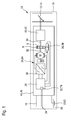
- FIG. 1 shows a block diagram of the adjusting drive 10 according to the invention for adjusting a movable part 12 in a motor vehicle.
- the following is at the moving part 12 is always assumed by an air distribution flap 14 of a motor vehicle air conditioning 16.
- other movable parts 12 of the motor vehicle for example seats, sliding roofs, windows or the like, can also be moved with the adjusting drive 10.
- the adjustment drive 10 is supplied with energy via a power supply connection 18, 20, wherein a supply contact 18 is connected to a supply voltage of a not shown energy source, for example a motor vehicle battery, and a ground contact 20 to ground GND. Furthermore, the adjustment drive has a data interface 22, which is preferably designed as a serial interface of a LIN bus system 24. By means of the data interface 22, at least one rotational angle desired value, a desired rotational speed and / or a desired rotational direction for controlling or controlling a DC motor 26, in particular a DC collector motor, by a higher-level control unit (master), not shown, are received. Likewise, the data interface 22 is suitable for sending a drive state of the adjustment drive 10 to the master.
- the data interface 22 is part of a control electronics 28, which is used to control or control the DC motor 26 via a power electronics 30 by means of a pulse width modulation (PWM) with a frequency of, for example, about 20 kHz. If, when the air distributor flap 14 is moved out of the stop, an increased torque is required at low ambient temperatures, then the DC motor 26 can additionally be driven at low frequency with a frequency of 5 to 25 Hz, i. This low-frequency modulation is superimposed on the actual PWM, in order to better overcome the static friction moments.
- PWM pulse width modulation
- a segmented magnetic ring 34 Connected to the DC motor in a rotationally fixed manner on a motor shaft 32 is a segmented magnetic ring 34 whose segments consist of magnets of alternating polarity (N, S).
- This magnetic ring 34 acts on a fixedly mounted rotation angle sensor 36, for example, a Hall sensor 38 or the like, which is electrically connected to the control electronics 28 and for non-contact detection of rotation angles of the motor shaft 32 is used.
- the motor shaft 32 of the DC motor 26 is connected to an output element 40, which is designed as a mechanical reduction gear 42.
- the adjustment 10 is surrounded by a housing 44 which is advantageously formed as a plastic housing 46.
- a housing 44, 46 The design of the housing 44, 46 will be discussed in detail in connection with FIGS. 3 and 4.
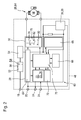
- FIG. 2 gives an overview of the electronics 48 used in the adjustment drive 10 for controlling the DC motor 26. This consists essentially of the already mentioned control electronics 28, the power electronics 30, the rotation angle sensor 36, a protection device against electrostatic discharge (ESD protection) 50 a filter connected to the supply voltage applied to the supply contact 18 against electromagnetic interference (EMC filter) 52 and an energy buffer 54th
- the EMC filter is formed as a filter of the first order and constructed of a series resistor 56 and a capacitor 58, whereby filters of higher orders can be used.
- the capacitor 58 of the EMC filter can additionally serve as an energy buffer 54 in order to bridge power supply breakdowns for short periods of time.
- the voltage regulator 64 generates an ASIC-internal voltage of 3.3 V from the supply voltage of the motor vehicle (usually approximately 12 to 14 V) present at the supply contact 18. This serves to supply the ASIC 60 and as the reference voltage for the A / D-converter 68. Furthermore, the ASIC-internal voltage can also be used for an over-temperature detection logic, not shown, of the ASIC 60, which causes a shutdown of the adjustment 10 in the event of an overtemperature warning.
- the data interface 22 is - as already mentioned above - designed as a serial interface of a LIN bus system 24. It therefore operates as a so-called LIN bus interface 74 in which the physical layer (LIN hardware) is implemented.
- the LIN bus interface 74 consists of a LIN transceiver and a state machine (finite state machine). The latter recognizes the baud rate, detects message beginning and end and writes the byte received by the master in each case into special memory structures (Special Function Register) of the microcontroller 70, which is informed of the received byte with the aid of interrupts.
- the state machine reads the values from the Special Function Register of the microcontroller 70 and inserts a stop bit at the end of the message.
- the data interface 22 performs automatic addressing, which is usually initiated by the master.
- the automatic addressing take along with the adjustment 10 all other, connected to the LIN bus 24 actuators of the motor vehicle part.
- the last actuator in the series is detected with the aid of a LIN transceiver operating as its LIN transmitter and a LIN transceiver of a preceding actuator located as a LIN receiver, which has a 1-ohm series resistance at which a voltage drop is measured becomes. If the voltage drop falls below a certain threshold, then the corresponding actuator is the last in the series. This takes over the address transmitted by the master and ends its Addressing sequence.
- the addressing is continued until all actuators have a valid address. Is in this way the adjustment 10 integrated into the LIN bus system 24, the address and other relevant to the adjustment 10 data, such as the direction of rotation of the DC motor 26, stored in the memory 66, wherein the programming of the microprocessor 70 ensured becomes.
- the ASIC 60 also contains the power electronics 30.
- This is usually designed as a so-called H-bridge 76, which consists of two high-side PMOS transistors 78 and two low-side NMOS transistors 80 exists, between each of which a tap 82 is provided for the DC motor 26.
- the low-side NMOS transistors 80 are clocked by PWM.
- the so-called synchronous-rectification method freewheeling via the high-side switched-over PMOS transistors 78) is used to reduce thermal losses.
- the H-bridge 76 is protected by an overcurrent or short circuit detection and switches off automatically in case of overload.
- a / D converter 68 which is based on a SAR structure (successive approximation register, i.e. bits are determined in succession in descending order), optionally up to two external A / D channels and the supply voltage can be measured.
- the respective selection is software-controlled with an on-chip multiplexer.
- the detection of the supply voltage is required for independent of the electrical system control of the DC motor 26.
- a temperature sensor in the air conditioning system 16 of the motor vehicle or as an alternative position detection of the movable part 12, a potentiometer, not shown, can be read.
- the software is stored in the ROM of the microcontroller 70, wherein it is ensured by the monitoring device 72 that the microcontroller 70, should it be in an undefined state, is reset.
- the software shows the logical layer and the application layer of the LIN protocol. Accordingly, the data bytes received by the LIN transceiver 74 are interpreted. For command messages, the required actions are performed as far as possible. After a request message, the generation of a corresponding response message including a checksum to ensure error detection and / or correction takes place.
- the fault detection includes the following types of fault: short circuit / overcurrent in the H-bridge 76, overtemperature, exceeding and falling below the supply voltage, LIN timeout and blockage of the DC motor 26 and the movable member 12, although no current through a DC despite energization of the DC motor 26 defined period is detected (end stop detection).
- end stop detection In the case of a functioning LIN communication, the master is informed of the status of the adjustment drive 10 upon request. If, on the other hand, problems occur during the LIN bus communication, the adjusting drive 10 runs to its emergency stop position defined by the master. For example, the air distribution flap 14, if it works as a fresh air recirculation controller set to fresh air.
- the software takes on the task of evaluating the measured voltage drop and controlling the corresponding auto-addressing steps, such as turning on or off the current sources and pull-up resistors (not shown) incorporated in the ASIC 60, as well as programming the memory 66 ,
- the blockage detection is used to determine the end stops. These are reported to the master (in counting steps of the rotation angle sensor 36).
- An implemented PI speed controller ensures a smooth start-up of the DC motor 26 for noise and starting current reduction. At various loads and a changing supply voltage of the PI speed controller reacts with an adjustment of the duty cycle of the PWM to ensure a constant speed of the DC motor 26.
- the rotational speed of the DC motor 26 is reduced via a reduction in the PWM duty cycle so that the DC motor 26 smoothly discharges. This reduces the noise and improves the exact achievement of the target position.
- the 6-volt DC motor 84 can be operated in the short term with a higher torque to overcome any blockage or stiffness. Alternatively or additionally, the blockage or stiffness can also be overcome by turning back the DC motor 26 and subsequent activation with the maximum motor current. These The procedure, however, is to avoid surveying or, if the air distributor flap 14 is in the stop.
- a PWM frequency of about 20 kHz.
- the DC motor 26 to better overcome the Haftreibmomente additionally low-frequency with a frequency of 5 to 25 Hz, which superimposed the actual PWM frequency is to be clocked.
- the maximum motor current of the DC motor 26 can be adapted to different environmental conditions. In this way it is possible to reduce the maximum motor current at an increasing ambient temperature in order to avoid overheating of the adjusting drive 10.
- control electronics 28 always causes a start of the target position of the air distribution flap 14 from the same direction. Furthermore, logic is included in the microcontroller 70 that allows detection of an unintended change in position of the air distribution door 14.
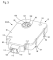
- FIG. 3 shows a first exemplary embodiment of the housing 44 of the adjusting drive 10 in an assembled state. It has the very compact dimensions for an adjustment 10 of about 55 mm in width, about 90 mm in length and about 25 mm in height.
- the housing 44 is formed as a plastic housing 46 and consists of a lower shell 88 and an upper shell or a lid 90, wherein the upper shell or the cover 90 has latching hooks 92 for latching with corresponding latching receptacles 94 of the lower shell 88.
- the upper shell or the cover 90 and the lower shell 88 may also be screwed, glued or welded (for example by means of laser welding).
- the housing 86 in particular the upper shell or the cover 90, has a recess 96 for a rotatable, with the output member 40 (not visible in Figure 3) in operative connection receptacle 98, which in turn has an opening 100 with at her opening periphery formed formations 102 for transmitting the torque generated by the output member 40 on the drive shaft, not shown, the air distributor flap 14.
- the contour of the formations 102 may be arbitrary. In the simplest case, it is a rectangular slot. Likewise, however, symmetrical or asymmetrical oval, triangular or - as shown in Figure 3 - polygonal shapes are conceivable.
- the receptacle 98 is guided at its outer periphery 104 through the recess 96 of the upper shell or the cover 90, wherein between the receptacle 98 and recess 96, an air gap for a low-friction rotational movement possible remains.
- the opening 100 of the receptacle 98 may also be formed in a continuous cylindrical shape with the protrusions 102, so that both the upper shell or the cover 90 and the lower shell 88 of the housing 86 have a corresponding recess 96 for guiding the receptacle 98.
- This offers the advantage that the adjustment drive 10 can be plugged at any distance onto the drive axis of the air distribution flap 14. Furthermore, a tilting of the adjustment drive 10 on the drive axle can be largely avoided in this way.
- the lower shell 88 has a housing part 106 which is designed as a plug or socket and contacts 108 (see FIG. 4 b) for the energy supply connection 18, 20 and the data interface 22.
- guide elements 110 are provided in the housing part 106. These can simultaneously serve as locking elements for the inserted plug or the inserted socket to prevent accidental release.
- corresponding fastening openings 112 are provided as fixing points in the upper shell or the cover 90 and in the lower shell 88 of the housing 86.
- the adjustment drive 10 can either be screwed or attached to the body part.
- an optimization of the damping properties of the plastic housing 46 and its attachment points is possible by the spatial design and material selection.
- FIG. 4a shows a further exemplary embodiment of the housing 44 of the adjusting drive 10 in an oblique representation with the upper cover or raised cover 90 lifted off.
- the latching hooks 92 of the upper shell or cover 90 and the latching receptacles 94 of the lower shell 88 and the fastening openings 112 are here However, only in the upper shell or the lid 90 are provided to recognize.
- the lower shell 88 has receptacles for the output element 40, the DC motor 26, 84 and the circuit board 62, which in turn according to Figure 4b with the control electronics 28 and the power electronics 30 in the form of the ASIC 60, the ESD protection 50, the EMC filter 52nd , the energy buffer 54 and the Hall sensor 38 designed as rotational angle sensor 36 is equipped.
- circuit board 62 the above-mentioned contacts 108 which are shaped so that they protrude with appropriate fitting of the circuit board 62 in the lower shell 88 in serving as a socket or plug housing part 106 of the lower shell 88 and thus as the electrical contact part of the socket or of the plug.
- appropriate guide elements 110 which can serve as locking elements for the plug or the socket at the same time.
- the output element 40 is formed in FIG. 4 a as a reduction drive 42. It is driven by means of a screw 114 mounted on the motor shaft 32 in a rotationally fixed manner and is in operative connection with the downwardly directed receptacle 98 (not visible in FIG. 4 a), the guidance of which is now effected by a recess in the lower shell 88. Alternatively, of course, in this embodiment, a continuous through the entire housing 86 opening of the receptacle 98 are used.
- the plastic housing has walls 115 which extend in the axial direction of the gears 116 and surrounding them in a defined, radial distance of not more than 1.2 mm over a maximum angular range.
- the rotationally fixed on the motor shaft 32 mounted screw 114 may be made either of plastic, of metal, or of a plastic-bonded magnetic material. In the latter case, it is possible to use the worm 114 not only as a drive element for a metal worm wheel 117 of the reduction gear 42 but also as a segmented magnetic ring 34 for the rotation angle detection by means of the rotation angle sensor 36. In this case, the segmentation of the plastic-bonded magnetic material takes place at least over a defined axial region, which is covered by a scanning field of the rotational angle sensor 36.
- the worm 114 is made of the plastic-bonded magnetic material in the region where it contacts the metal worm wheel 116 (alternatively, the worm 114 may of course be made entirely of the plastic-bonded magnetic material), it may be used with the resultant magnetic force the self-adjustment in the metal worm wheel 117 hold. An elaborate storage of the motor shaft 32 in the lower shell 88 can thus be dispensed with.
- the embodiments shown are limited neither to the figures 1 to 4 nor to the dimensions or shapes of the housing 44 mentioned.
- the adjusting drive 10 according to the invention can also be used in conjunction with bus systems other than the LIN bus.
- the transistors 78, 80 used in the H-bridge 74 are not limited to PMOS or NMOS types. Instead, conventional bipolar transistors, IGBTs or FET can be used.
- the DC motor 26 instead of an H-bridge and a B-circuit can be used as power electronics 30.
- the adjustment 10 is used in a particularly advantageous manner as a louver, but the embodiments should not be understood as a limitation with respect to its application in this application.
Landscapes
- Engineering & Computer Science (AREA)
- Human Computer Interaction (AREA)
- Manufacturing & Machinery (AREA)
- Physics & Mathematics (AREA)
- General Physics & Mathematics (AREA)
- Automation & Control Theory (AREA)
- Control Of Direct Current Motors (AREA)
Applications Claiming Priority (1)
| Application Number | Priority Date | Filing Date | Title |
|---|---|---|---|
| DE200610028634 DE102006028634A1 (de) | 2006-06-22 | 2006-06-22 | Verstellantrieb zum Verstellen mindestens eines beweglichen Teils in einem Kraftfahrzeug |
Publications (1)
| Publication Number | Publication Date |
|---|---|
| EP1871002A2 true EP1871002A2 (fr) | 2007-12-26 |
Family
ID=38565329
Family Applications (1)
| Application Number | Title | Priority Date | Filing Date |
|---|---|---|---|
| EP20070106895 Withdrawn EP1871002A2 (fr) | 2006-06-22 | 2007-04-25 | Mécanisme de déplacement destiné au réglage d'au moins deux pièces mobiles dans un véhicule automobile |
Country Status (2)
| Country | Link |
|---|---|
| EP (1) | EP1871002A2 (fr) |
| DE (1) | DE102006028634A1 (fr) |
Cited By (2)
| Publication number | Priority date | Publication date | Assignee | Title |
|---|---|---|---|---|
| CN101982650A (zh) * | 2010-10-19 | 2011-03-02 | 远华京控(北京)科技有限公司 | 电动执行装置 |
| DE102017215227A1 (de) | 2017-08-31 | 2019-02-28 | Robert Bosch Gmbh | Verfahren zur Variation der PWM-Frequenz bei bürstenlosen Gleichstrommotoren |
Families Citing this family (6)
| Publication number | Priority date | Publication date | Assignee | Title |
|---|---|---|---|---|
| DE202009005837U1 (de) | 2009-04-18 | 2010-09-16 | Brose Fahrzeugteile Gmbh & Co. Kommanditgesellschaft, Hallstadt | Schaltungsanordnung zum Betrieb eines Gleichstrommotors |
| DE102009027239B4 (de) * | 2009-06-26 | 2013-08-08 | Geze Gmbh | Türanlage |
| DE102013225629B3 (de) | 2013-12-11 | 2015-04-02 | Röchling Automotive SE & Co. KG | Luftleitsystem mit integrierter Diagnoseeinrichtung für ein Kraftfahrzeug |
| DE102018112808A1 (de) | 2018-05-29 | 2019-03-14 | Dr. Schneider Kunststoffwerke Gmbh | Aktuator und System mit Aktuator |
| DE102022109690A1 (de) | 2022-04-21 | 2023-10-26 | Bayerische Motoren Werke Aktiengesellschaft | Motorplatine und System zur Ansteuerung eines Elektromotors von Fahrzeugkomponenten |
| DE102022134219B3 (de) | 2022-12-20 | 2023-12-21 | Dr. Ing. H.C. F. Porsche Aktiengesellschaft | Aktuator zum Steuern eines Verstellweges eines Ventils sowie Verfahren zum Messen des Toleranzausgleiches und Wassermischventil mit einem derartigen Aktuator |
-
2006
- 2006-06-22 DE DE200610028634 patent/DE102006028634A1/de not_active Withdrawn
-
2007
- 2007-04-25 EP EP20070106895 patent/EP1871002A2/fr not_active Withdrawn
Cited By (2)
| Publication number | Priority date | Publication date | Assignee | Title |
|---|---|---|---|---|
| CN101982650A (zh) * | 2010-10-19 | 2011-03-02 | 远华京控(北京)科技有限公司 | 电动执行装置 |
| DE102017215227A1 (de) | 2017-08-31 | 2019-02-28 | Robert Bosch Gmbh | Verfahren zur Variation der PWM-Frequenz bei bürstenlosen Gleichstrommotoren |
Also Published As
| Publication number | Publication date |
|---|---|
| DE102006028634A1 (de) | 2007-12-27 |
Similar Documents
| Publication | Publication Date | Title |
|---|---|---|
| EP1871002A2 (fr) | Mécanisme de déplacement destiné au réglage d'au moins deux pièces mobiles dans un véhicule automobile | |
| DE10358596B4 (de) | Elektrisches Stellantriebssystem | |
| DE10231452A1 (de) | Lüftersteuerungssystem unter Verwendung einer Mikrosteuerung | |
| DE60020078T2 (de) | Verbesserungen an Klemmschutzvorrichtungen für Automobile | |
| EP1425842A2 (fr) | Unite d'entrainement comportant un moteur electrique, destinee a des dispositifs de reglage de vehicules | |
| DE102013108258A1 (de) | Antriebssystem für einen Fahrzeuganhängerrangierantrieb | |
| WO2011120606A1 (fr) | Procédé pour commander un système d'entraînement d'un élément de réglage d'un véhicule automobile et système d'entraînement correspondant | |
| DE102006039257A1 (de) | Verstellvorrichtung für ein bewegliches Karosserieteil eines Kraftfahrzeugs sowie Verfahren zur Verstellung des beweglichen Karosserieteils | |
| DE102018112808A1 (de) | Aktuator und System mit Aktuator | |
| EP1987584B1 (fr) | Mécanisme d'entraînement d'un dispositif de réglage permettant de régler une pièce de véhicule et procédé de fonctionnement de ce mécanisme d'entraînement | |
| DE102015113517B4 (de) | Verfahren zur Steuerung eines motorischen Klappenantriebs und Klappenantrieb zur Einstellung eines Fluidstroms | |
| DE2944224A1 (de) | Steueranordnung fuer eine wischanlage fuer kraftfahrzeugscheiben | |
| DE19939861B4 (de) | Motor-Laststeuersystem | |
| EP2321158B1 (fr) | Procede et dispositif de commande pour moteur electrique | |
| EP1739266B1 (fr) | Système de commande d'un lève-vitre de véhicule | |
| EP0865148A1 (fr) | Moteur à collecteur avec un capteur de fonctionnement | |
| DE102018108162A1 (de) | Stellvorrichtung und Verfahren zur Steuerung einer Stellvorrichtung | |
| EP3063505B1 (fr) | Capteur de position permettant de détecter une position d'un actionneur | |
| DE102012102869A1 (de) | Verfahren zur Ansteuerung eines bürstenlosen Elektromotors | |
| EP1672777B1 (fr) | Dispositif de commande pour des composants de véhicules | |
| EP2755318B1 (fr) | Système de volets | |
| DE102018219505A1 (de) | Verfahren zum Betrieb einer elektromotorischen Verstellvorrichtung eines Kraftfahrzeugs | |
| EP1727270B1 (fr) | Actionneur avec moteur électrique et dispositif de réglage pour commander la vitesse du moteur | |
| EP1873899A2 (fr) | Commande de la vitesse du ventilateur et procédé destiné au réglage de la vitesse d'un ventilateur | |
| DE112005000322T5 (de) | Motorantriebsvorrichtung |
Legal Events
| Date | Code | Title | Description |
|---|---|---|---|
| PUAI | Public reference made under article 153(3) epc to a published international application that has entered the european phase |
Free format text: ORIGINAL CODE: 0009012 |
|
| AK | Designated contracting states |
Kind code of ref document: A2 Designated state(s): AT BE BG CH CY CZ DE DK EE ES FI FR GB GR HU IE IS IT LI LT LU LV MC MT NL PL PT RO SE SI SK TR |
|
| AX | Request for extension of the european patent |
Extension state: AL BA HR MK YU |
|
| STAA | Information on the status of an ep patent application or granted ep patent |
Free format text: STATUS: THE APPLICATION IS DEEMED TO BE WITHDRAWN |
|
| 18D | Application deemed to be withdrawn |
Effective date: 20141101 |