EP1872019B1 - Dispositif d'entrainement comportant un regulateur de position - Google Patents
Dispositif d'entrainement comportant un regulateur de position Download PDFInfo
- Publication number
- EP1872019B1 EP1872019B1 EP06707111A EP06707111A EP1872019B1 EP 1872019 B1 EP1872019 B1 EP 1872019B1 EP 06707111 A EP06707111 A EP 06707111A EP 06707111 A EP06707111 A EP 06707111A EP 1872019 B1 EP1872019 B1 EP 1872019B1
- Authority
- EP
- European Patent Office
- Prior art keywords
- drive
- drive device
- chamber
- cover
- cartridge
- Prior art date
- Legal status (The legal status is an assumption and is not a legal conclusion. Google has not performed a legal analysis and makes no representation as to the accuracy of the status listed.)
- Expired - Lifetime
Links
Images
Classifications
-
- F—MECHANICAL ENGINEERING; LIGHTING; HEATING; WEAPONS; BLASTING
- F15—FLUID-PRESSURE ACTUATORS; HYDRAULICS OR PNEUMATICS IN GENERAL
- F15B—SYSTEMS ACTING BY MEANS OF FLUIDS IN GENERAL; FLUID-PRESSURE ACTUATORS, e.g. SERVOMOTORS; DETAILS OF FLUID-PRESSURE SYSTEMS, NOT OTHERWISE PROVIDED FOR
- F15B15/00—Fluid-actuated devices for displacing a member from one position to another; Gearing associated therewith
- F15B15/20—Other details, e.g. assembly with regulating devices
- F15B15/28—Means for indicating the position, e.g. end of stroke
- F15B15/2815—Position sensing, i.e. means for continuous measurement of position, e.g. LVDT
- F15B15/2853—Position sensing, i.e. means for continuous measurement of position, e.g. LVDT using potentiometers
-
- F—MECHANICAL ENGINEERING; LIGHTING; HEATING; WEAPONS; BLASTING
- F15—FLUID-PRESSURE ACTUATORS; HYDRAULICS OR PNEUMATICS IN GENERAL
- F15B—SYSTEMS ACTING BY MEANS OF FLUIDS IN GENERAL; FLUID-PRESSURE ACTUATORS, e.g. SERVOMOTORS; DETAILS OF FLUID-PRESSURE SYSTEMS, NOT OTHERWISE PROVIDED FOR
- F15B15/00—Fluid-actuated devices for displacing a member from one position to another; Gearing associated therewith
- F15B15/08—Characterised by the construction of the motor unit
- F15B15/14—Characterised by the construction of the motor unit of the straight-cylinder type
- F15B15/1423—Component parts; Constructional details
- F15B15/1433—End caps
-
- F—MECHANICAL ENGINEERING; LIGHTING; HEATING; WEAPONS; BLASTING
- F15—FLUID-PRESSURE ACTUATORS; HYDRAULICS OR PNEUMATICS IN GENERAL
- F15B—SYSTEMS ACTING BY MEANS OF FLUIDS IN GENERAL; FLUID-PRESSURE ACTUATORS, e.g. SERVOMOTORS; DETAILS OF FLUID-PRESSURE SYSTEMS, NOT OTHERWISE PROVIDED FOR
- F15B15/00—Fluid-actuated devices for displacing a member from one position to another; Gearing associated therewith
- F15B15/08—Characterised by the construction of the motor unit
- F15B15/14—Characterised by the construction of the motor unit of the straight-cylinder type
- F15B15/1423—Component parts; Constructional details
- F15B15/1438—Cylinder to end cap assemblies
-
- F—MECHANICAL ENGINEERING; LIGHTING; HEATING; WEAPONS; BLASTING
- F15—FLUID-PRESSURE ACTUATORS; HYDRAULICS OR PNEUMATICS IN GENERAL
- F15B—SYSTEMS ACTING BY MEANS OF FLUIDS IN GENERAL; FLUID-PRESSURE ACTUATORS, e.g. SERVOMOTORS; DETAILS OF FLUID-PRESSURE SYSTEMS, NOT OTHERWISE PROVIDED FOR
- F15B15/00—Fluid-actuated devices for displacing a member from one position to another; Gearing associated therewith
- F15B15/20—Other details, e.g. assembly with regulating devices
- F15B15/202—Externally-operated valves mounted in or on the actuator
-
- F—MECHANICAL ENGINEERING; LIGHTING; HEATING; WEAPONS; BLASTING
- F15—FLUID-PRESSURE ACTUATORS; HYDRAULICS OR PNEUMATICS IN GENERAL
- F15B—SYSTEMS ACTING BY MEANS OF FLUIDS IN GENERAL; FLUID-PRESSURE ACTUATORS, e.g. SERVOMOTORS; DETAILS OF FLUID-PRESSURE SYSTEMS, NOT OTHERWISE PROVIDED FOR
- F15B15/00—Fluid-actuated devices for displacing a member from one position to another; Gearing associated therewith
- F15B15/20—Other details, e.g. assembly with regulating devices
- F15B15/28—Means for indicating the position, e.g. end of stroke
- F15B15/2815—Position sensing, i.e. means for continuous measurement of position, e.g. LVDT
- F15B15/2861—Position sensing, i.e. means for continuous measurement of position, e.g. LVDT using magnetic means
-
- F—MECHANICAL ENGINEERING; LIGHTING; HEATING; WEAPONS; BLASTING
- F15—FLUID-PRESSURE ACTUATORS; HYDRAULICS OR PNEUMATICS IN GENERAL
- F15B—SYSTEMS ACTING BY MEANS OF FLUIDS IN GENERAL; FLUID-PRESSURE ACTUATORS, e.g. SERVOMOTORS; DETAILS OF FLUID-PRESSURE SYSTEMS, NOT OTHERWISE PROVIDED FOR
- F15B15/00—Fluid-actuated devices for displacing a member from one position to another; Gearing associated therewith
- F15B15/20—Other details, e.g. assembly with regulating devices
- F15B15/28—Means for indicating the position, e.g. end of stroke
- F15B15/2892—Means for indicating the position, e.g. end of stroke characterised by the attachment means
-
- F—MECHANICAL ENGINEERING; LIGHTING; HEATING; WEAPONS; BLASTING
- F15—FLUID-PRESSURE ACTUATORS; HYDRAULICS OR PNEUMATICS IN GENERAL
- F15B—SYSTEMS ACTING BY MEANS OF FLUIDS IN GENERAL; FLUID-PRESSURE ACTUATORS, e.g. SERVOMOTORS; DETAILS OF FLUID-PRESSURE SYSTEMS, NOT OTHERWISE PROVIDED FOR
- F15B21/00—Common features of fluid actuator systems; Fluid-pressure actuator systems or details thereof, not covered by any other group of this subclass
- F15B21/08—Servomotor systems incorporating electrically operated control means
- F15B21/085—Servomotor systems incorporating electrically operated control means using a data bus, e.g. "CANBUS"
-
- F—MECHANICAL ENGINEERING; LIGHTING; HEATING; WEAPONS; BLASTING
- F15—FLUID-PRESSURE ACTUATORS; HYDRAULICS OR PNEUMATICS IN GENERAL
- F15B—SYSTEMS ACTING BY MEANS OF FLUIDS IN GENERAL; FLUID-PRESSURE ACTUATORS, e.g. SERVOMOTORS; DETAILS OF FLUID-PRESSURE SYSTEMS, NOT OTHERWISE PROVIDED FOR
- F15B15/00—Fluid-actuated devices for displacing a member from one position to another; Gearing associated therewith
- F15B15/08—Characterised by the construction of the motor unit
- F15B15/14—Characterised by the construction of the motor unit of the straight-cylinder type
- F15B15/1423—Component parts; Constructional details
- F15B15/1466—Hollow piston sliding over a stationary rod inside the cylinder
-
- F—MECHANICAL ENGINEERING; LIGHTING; HEATING; WEAPONS; BLASTING
- F15—FLUID-PRESSURE ACTUATORS; HYDRAULICS OR PNEUMATICS IN GENERAL
- F15B—SYSTEMS ACTING BY MEANS OF FLUIDS IN GENERAL; FLUID-PRESSURE ACTUATORS, e.g. SERVOMOTORS; DETAILS OF FLUID-PRESSURE SYSTEMS, NOT OTHERWISE PROVIDED FOR
- F15B15/00—Fluid-actuated devices for displacing a member from one position to another; Gearing associated therewith
- F15B15/20—Other details, e.g. assembly with regulating devices
- F15B15/28—Means for indicating the position, e.g. end of stroke
- F15B15/2815—Position sensing, i.e. means for continuous measurement of position, e.g. LVDT
Definitions
- the present invention relates to a drive device which has a fluid-actuated drive and which comprises a positioner enabling the positioning of the output part with control electronics and valve device.
- a controller and an actuator are housed in a common housing. Also located in the housing is a controllable by the electronic controller control valve, via which the fluid admission of two cylinder chambers of the fluid-operated drive is controlled.
- a drive device according to the preamble of claim 1 is made DE 3524414 A1 known.
- a drive device having a fluid-actuated drive, which has a drive housing defining a drive space in which at least one drive piston is linearly adjustable by fluid loading, motion-coupled to a driven part, and with one for the positioning of the at least one drive piston competent, a control electronics and a valve device having positioner, which is part of a regulator cartridge, which is inserted from the drive space axially opposite side through an installation opening through as a unit in a by axial extension of the drive housing axially adjacent to the drive space defined receiving space of the drive housing ,
- the positioner is received directly in the housing of the fluid-operated drive.
- the installation is very simple, because the positioner belongs to a designated as a control cartridge assembly that is inserted in a cartridge-like receiving space in the axial extension of the drive compartment. There is no need for separate installation and fastening measures for the individual components of the positioner, since these can be pre-assembled within the regulator cartridge, so that reduces the installation site on the drive to a few handling measures.
- the term "drive piston” should also be understood in the sense of a drive diaphragm.
- the drive space and the receiving space are expediently axially successively in the interior of a one-piece tubular body of the drive housing.
- a tubular body can be produced inexpensively by extrusion as a rule. You only need a pipe body of suitable length to simultaneously pretend the drive space and the directly adjacent receiving space.
- end wall is in particular a designed as part of the regulator cartridge disk body, which is circumferentially provided with a seal which is in sealing contact with the peripheral surface of the interior of the drive housing.
- the regulator cartridge inserted into the drive housing at the same time forms a closure cover which closes the installation opening of the receiving space.
- This can be dispensed with an otherwise possibly required separate cap.
- the cap in the Interacting with the drive housing at the same time also specify the depth of insertion of the regulator cartridge. This is particularly advantageous if the regulator cartridge is a plug-in part which can be inserted into the receiving space in the course of a pure insertion process.
- the end wall and the closure lid are expediently combined via one or more spacer elements to a support structure carrying the control electronics and the valve device.
- spacer elements For example, a plurality of spaced rod-like spacer elements may be provided, which are fixed at one end to the end wall and the other end on the closure lid.
- the control electronics and the valve device are expediently located in the space defined between the end wall and the closure lid.
- fluidic and electrical interfaces are preferably provided on the regulator cartridge, so that no corresponding measures must be taken on the drive housing. This allows a very simple production of the drive housing.
- the electrical control from the outside can be done both wired and wireless.
- the interfaces are preferably arranged on or in the closure lid, in particular in such a way that they are accessible from the outside of the closure lid which is axially opposite the drive space.
- a supply interface is expediently located underneath the electrical interfaces, to which the supply voltage required for the operation of the positioner can be created.
- at least one control interface is provided, which serves in particular to feed the desired position setpoint corresponding control signals by applying a more or less high drive current.
- At least one drive interface can also be embodied as a bus interface, which enables communication with an external electronic control device, wherein the positioner can be designed accordingly to enable activation using different bus protocols.
- the closure lid is equipped with manually operable controls and / or optical display means.
- the controls allow, for example, a manual activation in the application-specific device of the drive device or for maintenance purposes. Also, state values can be retrieved using the operating elements, which can then be visualized via the display means.
- the controls and / or display means are suitably electrically interconnected with an auxiliary electronic system in addition to the control electronics, which is expediently accommodated in the interior of the closure lid and in this case can be constructed on a circuit board.
- This auxiliary electronics in conjunction with a suitably designed control interface, may include bus electronics adapted to the respective protocol to be processed.
- a suitable for position detection of the drive piston or a motion-coupled with this component simply called “piston position" - suitable electronic position measuring device available.
- This can have a projecting into the drive space, preferably rod-like measuring component, which is a part of the regulator cartridge and automatically placed in place during installation of the regulator cartridge in place in the drive compartment.
- the measuring component dips more or less deeply into the drive piston as a function of the instantaneous axial position of the associated drive piston and a piston rod optionally connected thereto, acting as the output part.
- the drive device may be designed for the generation of either a linear or a rotary output movement of the driven part.
- the fluid-operated drive is then either a linear drive or a rotary drive, wherein in the case of the rotary drive, the linear movement of at least one drive piston is converted into a rotational movement of the driven part.
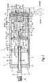
- the drive device provided in its entirety with reference numeral 1 contains as essential components a fluid-actuated drive 2 and a positioner 3 associated therewith.
- the drive 2 has a housing designated as a drive housing 4 with an elongated housing component, which is formed, in particular, by a one-piece tube body 5, preferably produced by extrusion.
- a housing designated as a drive housing 4 with an elongated housing component, which is formed, in particular, by a one-piece tube body 5, preferably produced by extrusion.
- the tubular body 5 is closed by a bearing cap 7, which also forms the front axial boundary of a formed in the drive housing 4 drive chamber 8, the back by a in the interior 9 of the Tubular body 5 inserted end wall 12 is limited.
- a drive piston 14 drivable for a linear drive movement 13 which is in sliding sealing contact with the inner surface of the tubular body 5 and the drive space 8 in a front working chamber 15 adjoining the bearing cover 7 and a rear working chamber 16 associated with the end wall 12 divided.
- a driven part 17 which is coupled in a coupled manner with the drive piston 14 is accessible outside the drive housing 4 and has there a mechanical interface 18 for connection to a component to be actuated, for example a slide of a shut-off valve used in the process industry.
- the drive movement 13 of the drive piston 14 causes a tappable at the interface output movement 22, for example, to open or close a shut-off valve.
- the output member 17 is formed as a piston rod, the bearing cap 7 under linear guidance and sealed interspersed. It performs a linear output movement 22 in accordance with the drive movement 13.
- first working chamber 15 opens via the bearing cap 7, a first fluid channel 23.
- the rear working chamber 16 is connected to a the end wall 12 passing through the second fluid channel 24 in connection.
- a fluidic pressure medium can be supplied and removed in a controlled manner in order to displace the drive piston 14 linearly in one or the other direction or to hold it at a specific position.
- the fluid-operated drive 2 is different from the exemplary linear drive a rotary drive.
- the drive space 8 are then conveniently two oppositely by fluid fluid displacement adjustable drive piston, which mesh via racks with a pinion, which is arranged on a shaft acting as a driven part, rotatably mounted in the drive housing 4 shaft, which is perpendicular to the direction of the drive movement 13.
- fluid fluid displacement adjustable drive piston which mesh via racks with a pinion, which is arranged on a shaft acting as a driven part, rotatably mounted in the drive housing 4 shaft, which is perpendicular to the direction of the drive movement 13.
- controlled fluid loading linear drive movement 13 causes a rotary output movement of the driven part.
- the fluid-operated drive 2 is therefore in particular a pneumatic drive.
- the drive housing 4 protrudes with its tubular body 5 axially beyond the end wall 12 placed in its interior and delimited axially in the connection to the drive space 8 on the circumference a receiving space 25 for the positioner 3.
- the interior 9 of the tubular body 5 has throughout expediently the same cross-section and is divided only by the inserted end wall 12 in the drive chamber 8 and coaxially arranged in extension to receiving space 25. To define the receiving space 25 therefore no additional housing must be grown.
- the drive housing 4 also functions as a housing for the positioner 3.
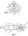
- the positioner 3 is characterized in that its various components, in particular its control electronics 26 and its electrically verifiable valve means 27, are not housed individually or separately in the receiving space 25, but on a designated as a regulator cartridge 28 assembly, as the components they executed are and the cartridge-like from the front side 6 opposite rear side 32 is used as a self-supporting unit axially into the receiving space 25.
- the insertion movement is in FIG. 3 indicated at 33 by an arrow.
- the installation and, if necessary, uninstalling the positioner 3 is very simplified because only the all relevant components having regulator cartridge 28 must be inserted or pulled out in the drive housing 4.
- the regulator cartridge 28 is designed as a plug-in part, which can be installed and removed without superimposed turning or screwing alone by a purely axial movement. In principle, however, a superimposed rotary motion would also be possible, in particular towards the end of the insertion movement 33.
- the drive space 8 in the interior of the one-piece component 5 of the drive housing 4 axially delimiting end wall 12 is an integral part of the regulator cartridge 28.
- a separate mounting of the end wall 12 is unnecessary. This is automatically installed at the onset of the regulator cartridge 28 and placed at the desired location in the interior of the drive housing 4.
- the end wall 12 carries in the region of its outer circumference a ring encircling seal 35 which is in sealing contact with the inner surface of the tubular body 5.
- the end wall 12 is formed in the embodiment of a disk body whose outline corresponds to the cross section of the housing interior.
- the seal 35 may be fixed in a circumferential groove of this disk body.
- the inserted regulator cartridge 28 forms expediently at the same time also a closure cap 36 for the installation opening 34.
- the cap 36 is part of the regulator cartridge 28 and is automatically installed or uninstalled during their installation or removal and you can dispense with a separate cap.
- the closure lid 36 in cooperation with the drive housing 4 at the same time also performs a limiting function by setting the insertion depth of the regulator cartridge 28.
- this is achieved in that the closure cap 36 has a larger cross-section than the receiving space 25, so that it at the rear end face 37 of the tubular body 5 comes to rest when the desired insertion depth is reached.
- a not shown in the drawing centering collar on the axial inner surface of the closure lid 36 expediently immersed a little way into the receiving space 25 and provides in combination with the end wall 12 for an exact coaxial alignment of the regulator cartridge 28 with respect to the drive housing.
- the end wall 12 and the closure lid 36 are connected by axially extending spacer members 38 between them to form a rigid support structure 42 fixed to each other and held at an axial distance from each other.
- the spacer elements 38 are preferably rod-shaped and arranged in a uniform circumferential distribution. In the embodiment, three such spacers 38 are provided. Compared to a single, for example, sleeve-like spacer element, this multiple arrangement of rod-shaped spacers 38 has the advantage that remain between window-like recesses, which facilitate the lateral access to the components of the positioner 3 with uninstalled regulator cartridge 28.
- the valve device 27 has two working ports 43, 44, which are each connected to one of the fluid channels 23, 24. About these working ports 43, 44, the drive fluid with respect to the working chambers 15, 16 is supplied and removed.
- An advantage of the illustrated design is that although the regulator cartridge 28 is one with respect to the drive housing 4 is separate component, the required fluidic connection to the fluid channels 23, 24 is automatically when the regulator cartridge 28 has been inserted into its receiving space 25.
- the regulator cartridge 28 includes a first and a second control channel 45, 46.
- the second control channel 46 is identical to the above-mentioned second fluid channel 24. It passes through the end wall 12 and opens directly into the adjoining rear working chamber 16. It is connected to the one working port 44 via a preferably flexible fluid line 47a.
- the second control channel 46 passes through the closure cap 36. It is connected at one end to the other working port 43 via a fluid line 47b.
- this first control channel 45 opens at the end face 37 facing the lid surface, so that it aligns with the there opening out the first fluid channel 23 which passes through the wall of the tubular body 5 axially and opens via the bearing cap 7 in the front working chamber 15.
- the abovementioned fluidic and electrical interfaces 52, 53 are expediently located on or in the closure lid 36. In this case, they are preferably placed on the outer end face of the closure lid 36 axially opposite the drive space 8 and are thus accessible from the rear side of the drive device 1.
- the fluidic interfaces 52 include a supply interface 52a and a disposal interface 52b. At the supply interface 52a, a fluid connection to a pressure source 48a, which supplies the working medium, can be established via a detachably connectable external fluid line 54.
- a silencer 55 may be installed at the disposal interface 52b as shown, allowing for low-noise venting to the immediate environment. Otherwise, a fluid line leading away the spent medium can also be connected to the disposal interface 52b.
- the fluidic interfaces 52 communicate with the closure lid 36 passing through channels 51, which open at the end wall 12 facing the inner surface of the closure lid 36, where further fluid lines 47 c, 47 d are connected to a feed connection 56 and one or a plurality of discharge or vent ports 57 of the valve device 27 lead.
- the internal fluid lines 47a-47d are designed in the embodiment as pressure fluid hoses. However, it may equally well be rigid lines or channels properly integrated into the regulator cartridge 28.
- the valve device 27 includes one or more electrically operable control valves 58. They are capable of causing a corresponding valve actuation according to their activation state that the working chambers 15, 16 are acted upon for the purpose of positioning the drive piston 14 with fluid or relieved or vented.
- the control assumes a single, designed as a 5/3-way valve control valve 58a, while another control valve 58b only acts as a safety valve, which assumes a preferred switching position in a power failure, the displacement of the drive piston 14 and the output member 17 in one Safety aspects harmless position causes.
- valve device 27 takes over the control electronics 26 integrated in the regulator cartridge 28.
- This is expediently constructed on one or more circuit boards 61.
- the at least one board 61 is fastened to the valve device 27, which in turn is held axially inwardly on the closure lid 36 via at least one fastening element 59.
- the operating energy or operating voltage required for the operation of the valve device 27 is fed in via one of the electrical interfaces 53, which functions as the electrical supply interface 53a. In the most Cases are here 24 volts.
- At least one additional electrical control interface 53b allows the input of an electrical control signal, which acts as a setpoint for the desired axial position of the drive piston 14. The setpoint is processed in the control electronics 26 and causes an electrical control signal for the valve means 27, which accordingly causes the fluid admission of the two working chambers 15, 16.
- the supply interface 53a can be connected to a voltage source 48b and the drive interface 53b to an electronic control device 48c.
- the existing or an additional drive interface 53b may be designed as a bus interface in order to be able to connect a bus which communicates with an external electronic control device 48c. Control signals as well as feedback signals can be returned via this bus.
- the drive device 1 is equipped with a position measuring device 63.
- This includes a rod-shaped measuring component 64, which is designed as part of the regulator cartridge 28 and projects axially from the end wall 12 into the drive chamber 8. Conveniently, the measuring component 64 is thereby attached to the end wall 12 that it passes through under sealing and is detachably screwed. Via electrical conductors 65, the measuring component 64 is electrically connected within the receiving space 25 with the control electronics 26.
- the measuring component 64 includes a linear potentiometer arranged in a protective tube 70 with a slider 66 bridging the conductor tracks, which is coupled by magnetic force to the drive piston 14.
- the latter carries in the embodiment at its the receiving space 25 facing the back of a permanent magnet means 67, which ensures that the slider 66 is always taken, so that a dependent of the linear position position signal is generated.
- the rod-shaped measuring component 64 is immersed in the drive piston 14 and the subsequent output part 17 position-dependent more or less.
- Drive piston 14 and driven part 17 are at least partially hollow for this purpose.
- the position measuring device 63 could also be based on another operating principle. It is essential to produce an electrical actual value corresponding to the actual position of the drive piston 14 or the output part 17, which is compared in the control electronics 26 with the externally setpoint value in order to activate the valve device 27 in such a way that the drive piston 14 is in the desired position Target position is shifted.
- the measuring component 64 is a component of the regulator cartridge 28, it is installed together with this in the drive housing 4 or uninstalled if necessary. During installation, it is inserted into the cavity of the drive piston 14 of the driven part 17.
- auxiliary electronics 62 which includes at least one circuit board, which is equipped with manually operable controls 68 and optical display means 69.
- operation-relevant data can be displayed, for example set value and actual value of the position control and / or the current operating mode, for example manual operating mode or automatic mode.
- the display means 69 contain this particular an alphanumeric display.
- the operating elements 68 may be, for example, switches or push buttons, via which the operation of the device can be controlled manually and / or entered and / or queried via the operating parameters.
- the useful at least one board having auxiliary electronics 62 is housed in the embodiment together with the controls 68 and the display means 69 in a Deckelaus strictlyung 72, which is covered by a cover 73 under sealing.
- the cover plate 73 is detachably, in particular by means not shown screws, arranged on the closure lid 36 and may, if necessary, the fluidic and / or electrical interfaces 52, 53 have.
- the cover plate 73 Opposite the display means 69, the cover plate 73 includes a sealed with transparent material first opening 74 so that the information displayed can be read from the outside.
- a control panel 68 opposite the second opening 75 of the cover plate 73 allows access to the controls 68 and is closed with a removable, preferably releasably screwed lid 76 with sealing. To operate the controls 68, the lid 76 is temporarily removed. The entire arrangement is designed so that even stricter tightness requirements is satisfied.
- the positioner 3 is to be controlled via an external bus, it also includes suitable bus electronics. This can be designed for processing different bus protocols.
- This bus electronics is like the other components of the positioner 3 on board the regulator cartridge 28 and is for example part of the auxiliary electronics 62nd
- the control of the actuator 3 by an external electronic control device can also be done wirelessly.
- at least one correspondingly formed electrical interface is provided on the regulator module 28, which is assigned, in particular, to a receiver and transmission electronics. This can also include a web browser.
- valve means 27 in such a case expediently a differential pressure proportional valve for controlling the two working chambers 15, 16 and pressure sensors for detecting the in the working chambers 15, 16 prevailing pressures are present.
Landscapes
- Engineering & Computer Science (AREA)
- Physics & Mathematics (AREA)
- Fluid Mechanics (AREA)
- Mechanical Engineering (AREA)
- General Engineering & Computer Science (AREA)
- Analytical Chemistry (AREA)
- Chemical & Material Sciences (AREA)
- Actuator (AREA)
- Vehicle Body Suspensions (AREA)
- Body Structure For Vehicles (AREA)
- Valve Device For Special Equipments (AREA)
- Coating Apparatus (AREA)
- Heating, Cooling, Or Curing Plastics Or The Like In General (AREA)
Claims (24)
- Dispositif d'entraînement avec entraînement actionné par fluide (2) qui présente un boîtier d'entraînement (4) délimitant une chambre d'entraînement (8) dans laquelle se trouve au moins un piston d'entraînement (14) susceptible d'être déplacé linéairement lorsqu'il est sollicité par un fluide et couplé en mouvement avec une partie de prise de mouvement (17), et avec un régulateur de position (3) permettant de positionner le piston d'entraînement (14) au nombre de un au moins et présentant un dispositif formant soupape (27), ledit régulateur de position (3) étant un composant d'une cartouche de régulateur (28), caractérisé en ce que la cartouche de régulateur (28) est montée comme une unité constructive du côté axialement opposé à la chambre d'entraînement (8) en passant par une ouverture d'installation (34) jusqu'à une chambre de réception (25) délimitée axialement à la suite de la chambre d'entraînement (8) par un prolongement monobloc du boîtier d'entraînement (4), et en ce que le régulateur de position (3) présente en outre une électronique de régulation (26).
- Dispositif d'entraînement selon la revendication 1, caractérisé en ce que la chambre d'entraînement (8) et la chambre de réception (25) sont disposées axialement l'une à la suite de l'autre dans la chambre intérieure (9) d'un corps tubulaire (5) monobloc du boîtier d'entraînement (4).
- Dispositif d'entraînement selon la revendication 2, caractérisé en ce que le corps tubulaire (5) est une pièce extrudée.
- Dispositif d'entraînement selon l'une des revendications 1 à 3, caractérisé en ce que la cartouche de régulateur (28) est une partie insérable susceptible d'être insérée dans le cadre d'un mouvement d'emboîtement axial dans la chambre de réception (25).
- Dispositif d'entraînement selon l'une des revendications 1 à 4, caractérisé en ce que la cartouche de régulateur (28) insérée dans le boîtier d'entraînement (4) forme simultanément une paroi d'extrémité (12) délimitant la chambre d'entraînement (8) sur le côté faisant face à la chambre de réception (25).
- Dispositif d'entraînement selon la revendication 5, caractérisé en ce que la paroi d'extrémité (12) est formée par un corps discoïde, équipé côté circonférence d'un joint, de la cartouche de régulateur (28).
- Dispositif d'entraînement selon l'une des revendications 1 à 5, caractérisé en ce que la cartouche de régulateur (28) insérée dans le boîtier d'entraînement (4) forme simultanément un couvercle de fermeture (36) fermant l'ouverture d'installation (34) de la chambre de réception (25).
- Dispositif d'entraînement selon la revendication 7, caractérisé en ce que le couvercle de fermeture (36) détermine à l'avance, par collaboration avec le boîtier d'entraînement (4), la profondeur d'insertion de la cartouche de régulateur (28).
- Dispositif d'entraînement selon la revendication 7 ou 8 en relation avec la revendication 5 ou 6, caractérisé en ce que la paroi d'extrémité (12) et le couvercle de fermeture (36) sont réunis par l'intermédiaire d'au moins un élément d'espacement (38) pour former une structure de support (42) supportant l'électronique de régulation (26) et le dispositif formant soupape (27).
- Dispositif d'entraînement selon la revendication 9, caractérisé par plusieurs éléments d'expacement (38) en forme de barres s'étendant à distance les uns des autres entre la paroi d'extrémité (12) et le couvercle de fermeture (36).
- Dispositif d'entraînement selon la revendication 9 ou 10, caractérisé en ce que l'électronique de régulation (26) et le dispositif de soupape (27) sont disposés axialement entre la paroi d'extrémité (12) et le couvercle de fermeture (36).
- Dispositif d'entraînement selon l'une des revendications 1 à 11, caractérisé en ce que toutes les interfaces électriques et fluidiques (52, 53) prévues pour la communication électrique et fluidique avec des dispositifs externes (48) sont disposées au niveau de la cartouche de régulateur (28).
- Dispositif d'entraînement selon la revendication 12 en relation avec l'une des revendications 7 à 11, caractérisé en ce que les interfaces (52, 53) sont disposées sur ou dans le couvercle de fermeture (36).
- Dispositif d'entraînement selon la revendication 12 ou 13, caractérisé en ce que les interfaces (52, 53) sont accessibles depuis le côté frontal extérieur éloigné de la chambre d'entraînement (8) du couvercle de fermeture (36).
- Dispositif d'entraînement selon l'une des revendications 12 à 14, caractérisé en ce que les interfaces électriques (53) comportent une interface d'alimentation (53a) servant à l'alimentation en énergie de commande et au moins une interface de commande (53b) pour les signaux de commande.
- Dispositif d'entraînement selon la revendication 15, caractérisé en ce qu'au moins une interface de commande (53b) est réalisée comme une interface de bus.
- Dispositif d'entraînement selon l'une des revendications 1 à 16, caractérisé en ce qu'au moins une interface électrique (53) prévue au niveau de la cartouche de régulateur (28) est réalisée pour la transmission sans fil des signaux.
- Dispositif d'entraînement selon l'une des revendications 7 à 17, caractérisé en ce que le couvercle de fermeture (36) présente, notamment dans la région du côté frontal éloigné de la chambre d'entraînement (8), des éléments de commande manuels (68) et/ou des moyens d'affichage optiques (69).
- Dispositif d'entraînement selon la revendication 18, caractérisé en ce qu'à l'intérieur du couvercle de fermeture (36) est placée une électronique auxiliaire (62) affectée aux éléments de commande (68) et/ou aux moyens d'affichage (69) et simultanément reliée à l'électronique de régulation (26).
- Dispositif d'entraînement selon la revendication 19, caractérisé en ce que l'électronique auxiliaire (62) est logée dans un évidement de couvercle (72), recouvert par une plaque de recouvrement (73), du couvercle de fermeture (36).
- Dispositif d'entraînement selon l'une des revendications 1 à 20, caractérisé par un dispositif de mesure de la position (63), réalisé au moins partiellement comme composant de la cartouche de régulateur (28), servant à détecter la position du piston.
- Dispositif d'entraînement selon l'une des revendications 1 à 21, caractérisé en ce que la cartouche de régulateur (28) présente un composant de mesure (64), pénétrant à l'intérieur de la chambre d'entraînement (8) et répondant à la position du piston, d'un dispositif électronique de mesure de la position (63).
- Dispositif d'entraînement selon la revendication 22, caractérisé en ce que le composant de mesure (64) s'enfonce dans le piston d'entraînement (14).
- Dispositif d'entraînement selon l'une des revendications 1 à 23, caractérisé en ce que la chambre d'entraînement (8) est divisée au moyen du piston d'entraînement (14) au nombre de un au moins en deux chambres de travail (15, 16), la cartouche de régulateur (28) présentant deux canaux de commande fluidiques (45, 46) se trouvant en liaison fluidique avec le dispositif formant soupape (27), l'un d'entre eux (46) débouchant directement dans la chambre de travail (16) contiguë à la cartouche de régulateur (28), tandis que l'autre est placé de telle sorte qu'il communique avec un canal fluidique interne (23) du boîtier d'entraînement (4) conduisant à l'autre chambre de travail (15) lorsque la cartouche de régulateur (28) est installée.
Applications Claiming Priority (2)
| Application Number | Priority Date | Filing Date | Title |
|---|---|---|---|
| DE200520006795 DE202005006795U1 (de) | 2005-04-22 | 2005-04-22 | Antriebsvorrichtung mit Stellungsregler |
| PCT/EP2006/001532 WO2006114147A1 (fr) | 2005-04-22 | 2006-02-21 | Dispositif d'entrainement comportant un regulateur de position |
Publications (2)
| Publication Number | Publication Date |
|---|---|
| EP1872019A1 EP1872019A1 (fr) | 2008-01-02 |
| EP1872019B1 true EP1872019B1 (fr) | 2009-11-04 |
Family
ID=34802371
Family Applications (1)
| Application Number | Title | Priority Date | Filing Date |
|---|---|---|---|
| EP06707111A Expired - Lifetime EP1872019B1 (fr) | 2005-04-22 | 2006-02-21 | Dispositif d'entrainement comportant un regulateur de position |
Country Status (7)
| Country | Link |
|---|---|
| US (1) | US7520208B2 (fr) |
| EP (1) | EP1872019B1 (fr) |
| CN (1) | CN101163891B (fr) |
| AT (1) | ATE447673T1 (fr) |
| DE (2) | DE202005006795U1 (fr) |
| DK (1) | DK1872019T3 (fr) |
| WO (1) | WO2006114147A1 (fr) |
Cited By (1)
| Publication number | Priority date | Publication date | Assignee | Title |
|---|---|---|---|---|
| WO2016037679A1 (fr) * | 2014-09-11 | 2016-03-17 | Festo Ag & Co. Kg | Commande de soupapes pneumatique |
Families Citing this family (27)
| Publication number | Priority date | Publication date | Assignee | Title |
|---|---|---|---|---|
| DE202009004673U1 (de) | 2008-08-29 | 2010-01-28 | Liebherr-Werk Ehingen Gmbh | Kolben-Zylinder-Einheit |
| US8448563B2 (en) * | 2008-08-29 | 2013-05-28 | Cowan Dynamics Inc. | Fluid-powered actuator having an internal position sensor and a sensor module therefor |
| CN101429955B (zh) * | 2008-12-11 | 2011-06-29 | 哈尔滨工程大学海能科技有限责任公司 | 伺服管定位流体驱动器 |
| CA2675497A1 (fr) * | 2009-08-18 | 2011-02-18 | Tcb Welding And Construction Ltd. | Ensemble de commutation pour chevalet de pompage hydraulique |
| DE202009014670U1 (de) * | 2009-10-30 | 2011-03-17 | Tipper Tie Technopack Gmbh | Positionierbarer Pneumatikzylinder |
| US9909601B2 (en) * | 2010-11-16 | 2018-03-06 | Illinois Tool Works Inc. | Motor control |
| DE102011013730B4 (de) | 2011-03-12 | 2013-11-28 | Heike Bedoian | Einrichtung zur Veränderung eines Verriegelungszustandes |
| CN103075385A (zh) * | 2011-10-26 | 2013-05-01 | 北京精密机电控制设备研究所 | 一种电动伺服油缸 |
| DE102012003230B3 (de) * | 2012-02-20 | 2013-03-21 | Festo Ag & Co. Kg | Prozessventil |
| US9128008B2 (en) * | 2012-04-20 | 2015-09-08 | Kent Tabor | Actuator predictive system |
| CN104395616B (zh) * | 2012-07-20 | 2016-08-17 | 博格华纳公司 | 内部位置传感器 |
| DE102013007927B4 (de) * | 2013-05-10 | 2014-12-24 | Hoerbiger Automatisierungstechnik Holding Gmbh | Antriebseinheit |
| CN103591079B (zh) * | 2013-11-28 | 2016-05-04 | 苏州蓝王机床工具科技有限公司 | 新型液压油缸 |
| DE102014013018A1 (de) * | 2014-09-02 | 2016-03-03 | Hydac System Gmbh | Hydraulisches System |
| DE102014013443B4 (de) * | 2014-09-11 | 2018-05-24 | Festo Ag & Co. Kg | Ventilantrieb |
| CN104265735A (zh) * | 2014-10-16 | 2015-01-07 | 山东同力液压装备有限公司 | 一种精密位移非接触式液压油缸 |
| CN104847863B (zh) * | 2015-03-17 | 2017-04-05 | 北京理工大学 | 一种电液混合式直线运动机构 |
| EP3271592B1 (fr) * | 2015-06-15 | 2019-12-11 | Festo AG & Co. KG | Entraînement rotatif muni d'un système fonctionnel modulaire |
| CN105202253A (zh) * | 2015-10-12 | 2015-12-30 | 罗普阀业(宜兴)有限公司 | 三位式气动执行器 |
| EP3428461B1 (fr) * | 2017-07-14 | 2021-01-20 | Hydraulique Production Systems | Verin hydraulique et installation mettant en oeuvre au moins un tel verin hydraulique |
| CN107989850B (zh) * | 2017-11-22 | 2020-08-18 | 中国航空工业集团公司金城南京机电液压工程研究中心 | 一种可调行程工程液压油缸 |
| US11719358B2 (en) | 2017-12-30 | 2023-08-08 | Itt Manufacturing Enterprises Llc | Switch for diaphragm valve actuator |
| DE102019134807B4 (de) * | 2019-12-17 | 2023-05-04 | Festo Se & Co. Kg | Aktuator für einen pneumatischen Linearantrieb und Verfahren zur Montage des Aktuators |
| US12352369B2 (en) | 2020-04-21 | 2025-07-08 | Phaedrus, Llc | Steam injection valve actuator, system, and method |
| CN114179343A (zh) * | 2021-12-06 | 2022-03-15 | 盐城市智成机械制造有限公司 | 一种可快速调节工作行程的压花机 |
| DE102022004564A1 (de) * | 2022-12-06 | 2024-06-06 | Bümach Engineering International B.V. | Verfahren zur Herstellung eines Arbeitszylinders mit einem Positionssensor |
| EP4538542A1 (fr) * | 2023-10-10 | 2025-04-16 | Goodrich Actuation Systems SAS | Ensemble actionneur |
Family Cites Families (10)
| Publication number | Priority date | Publication date | Assignee | Title |
|---|---|---|---|---|
| US3828556A (en) * | 1973-01-26 | 1974-08-13 | Johnson Service Co | Hydraulic actuator |
| JPS523987A (en) * | 1975-06-27 | 1977-01-12 | Kondo Seisakusho:Kk | Hydraulic drive device |
| CN85102322B (zh) * | 1985-04-01 | 1988-04-20 | 费斯托合资公司 | 滑座式驱动装置 |
| DE3524414C2 (de) * | 1985-04-16 | 1994-06-16 | Mannesmann Ag | Linearantrieb |
| DE19937597B4 (de) * | 1999-08-09 | 2005-11-24 | Abb Patent Gmbh | Druckmittelbetriebener Stellantrieb |
| US6282893B1 (en) * | 1999-08-19 | 2001-09-04 | Delaware Capital Formation, Inc. | Self-contained actuator |
| DE20004976U1 (de) * | 2000-03-17 | 2000-05-31 | Festo AG & Co, 73734 Esslingen | Fluidbetätigter Linearantrieb |
| DE10021744A1 (de) | 2000-05-04 | 2001-11-15 | Festo Ag & Co | Vorrichtung zur Einstellung des Differenzdrucks in einem Fluidzylinder |
| BR0110179A (pt) * | 2001-02-22 | 2003-03-05 | Festo Ag & Co | Cilindro de força com fluido |
| CN2512929Y (zh) * | 2001-11-13 | 2002-09-25 | 费斯托(中国)有限公司 | 一种气缸驱动装置 |
-
2005
- 2005-04-22 DE DE200520006795 patent/DE202005006795U1/de not_active Expired - Lifetime
-
2006
- 2006-02-21 CN CN2006800136556A patent/CN101163891B/zh not_active Expired - Fee Related
- 2006-02-21 AT AT06707111T patent/ATE447673T1/de active
- 2006-02-21 EP EP06707111A patent/EP1872019B1/fr not_active Expired - Lifetime
- 2006-02-21 US US11/662,510 patent/US7520208B2/en not_active Expired - Fee Related
- 2006-02-21 WO PCT/EP2006/001532 patent/WO2006114147A1/fr not_active Ceased
- 2006-02-21 DE DE502006005291T patent/DE502006005291D1/de not_active Expired - Lifetime
- 2006-02-21 DK DK06707111T patent/DK1872019T3/da active
Cited By (1)
| Publication number | Priority date | Publication date | Assignee | Title |
|---|---|---|---|---|
| WO2016037679A1 (fr) * | 2014-09-11 | 2016-03-17 | Festo Ag & Co. Kg | Commande de soupapes pneumatique |
Also Published As
| Publication number | Publication date |
|---|---|
| CN101163891B (zh) | 2010-09-29 |
| DK1872019T3 (da) | 2009-12-14 |
| CN101163891A (zh) | 2008-04-16 |
| DE202005006795U1 (de) | 2005-07-21 |
| EP1872019A1 (fr) | 2008-01-02 |
| WO2006114147A1 (fr) | 2006-11-02 |
| ATE447673T1 (de) | 2009-11-15 |
| US20080060509A1 (en) | 2008-03-13 |
| US7520208B2 (en) | 2009-04-21 |
| DE502006005291D1 (de) | 2009-12-17 |
Similar Documents
| Publication | Publication Date | Title |
|---|---|---|
| EP1872019B1 (fr) | Dispositif d'entrainement comportant un regulateur de position | |
| EP1274945B1 (fr) | Cylindre de travail | |
| DE102011012558B3 (de) | Druckluft-Wartungsgerät und damit ausgestattete Verbrauchersteuervorrichtung | |
| EP2728201B1 (fr) | Appareil de réglage électropneumatique et module électropneumatique | |
| DE112016005625B4 (de) | Vorrichtung zum Spritzgießen von Kunststoffmaterialien | |
| DE19653222C2 (de) | Halterung für Magnetfeldsensoren | |
| DE4108158C2 (de) | Linear-Antriebsvorrichtung | |
| EP2956689B1 (fr) | Actionneur électrique | |
| DE102016222242B4 (de) | Ventilanordnung und damit ausgestattete fluidbetätigte Stellvorrichtung | |
| EP1350960B1 (fr) | Dispositif d'entraínement actionné par fluide | |
| DE4229989A1 (de) | Dreh-Linear-Einheit | |
| DE102009040126A1 (de) | Elektromotorischer Hydraulikantrieb und Verfahren zum Bereitstellen eines definierten Hydraulikdrucks und/oder -volumens | |
| DE102013015105A1 (de) | Druckluft-Wartungsgerät, damit ausgestattete Verbrauchersteuervorrichtung und zugehöriges Betriebsverfahren | |
| DE29903281U1 (de) | Kniehebel-Spannvorrichtung | |
| DE20201058U1 (de) | Pneumatikantrieb | |
| EP3747612B1 (fr) | Dispositif de mélange d'au moins deux composants | |
| EP3271592A1 (fr) | Entraînement rotatif muni d'un système fonctionnel modulaire | |
| EP1430985B1 (fr) | Pince de soudage comprenant un entraînement linéaire programmable avec deux boucles indépendantes d'asservissement et procédé de commande de l'entraînement linéaire d'une telle pince de soudage | |
| DE29903825U1 (de) | Spannvorrichtung | |
| EP0439242A1 (fr) | Organe à mouvement rectiligne | |
| DE3811110A1 (de) | Kolbenantrieb | |
| DE4422528A1 (de) | Fluidbetätigte Antriebseinheit | |
| DE3741425C3 (de) | Linearantrieb | |
| EP2228576A1 (fr) | Dispositif de soupape | |
| DE102019202898A1 (de) | Antriebssystem |
Legal Events
| Date | Code | Title | Description |
|---|---|---|---|
| PUAI | Public reference made under article 153(3) epc to a published international application that has entered the european phase |
Free format text: ORIGINAL CODE: 0009012 |
|
| 17P | Request for examination filed |
Effective date: 20070120 |
|
| AK | Designated contracting states |
Kind code of ref document: A1 Designated state(s): AT BE BG CH CY CZ DE DK EE ES FI FR GB GR HU IE IS IT LI LT LU LV MC NL PL PT RO SE SI SK TR |
|
| RIN1 | Information on inventor provided before grant (corrected) |
Inventor name: MOEDINGER, UWE Inventor name: BEUTH, BERND |
|
| RAP1 | Party data changed (applicant data changed or rights of an application transferred) |
Owner name: FESTO AG & CO. KG |
|
| DAX | Request for extension of the european patent (deleted) | ||
| GRAP | Despatch of communication of intention to grant a patent |
Free format text: ORIGINAL CODE: EPIDOSNIGR1 |
|
| GRAS | Grant fee paid |
Free format text: ORIGINAL CODE: EPIDOSNIGR3 |
|
| GRAA | (expected) grant |
Free format text: ORIGINAL CODE: 0009210 |
|
| AK | Designated contracting states |
Kind code of ref document: B1 Designated state(s): AT BE BG CH CY CZ DE DK EE ES FI FR GB GR HU IE IS IT LI LT LU LV MC NL PL PT RO SE SI SK TR |
|
| REG | Reference to a national code |
Ref country code: GB Ref legal event code: FG4D Free format text: NOT ENGLISH |
|
| REG | Reference to a national code |
Ref country code: CH Ref legal event code: EP |
|
| REG | Reference to a national code |
Ref country code: IE Ref legal event code: FG4D |
|
| REG | Reference to a national code |
Ref country code: DK Ref legal event code: T3 |
|
| REF | Corresponds to: |
Ref document number: 502006005291 Country of ref document: DE Date of ref document: 20091217 Kind code of ref document: P |
|
| LTIE | Lt: invalidation of european patent or patent extension |
Effective date: 20091104 |
|
| PG25 | Lapsed in a contracting state [announced via postgrant information from national office to epo] |
Ref country code: SE Free format text: LAPSE BECAUSE OF FAILURE TO SUBMIT A TRANSLATION OF THE DESCRIPTION OR TO PAY THE FEE WITHIN THE PRESCRIBED TIME-LIMIT Effective date: 20091104 Ref country code: PT Free format text: LAPSE BECAUSE OF FAILURE TO SUBMIT A TRANSLATION OF THE DESCRIPTION OR TO PAY THE FEE WITHIN THE PRESCRIBED TIME-LIMIT Effective date: 20100304 Ref country code: LT Free format text: LAPSE BECAUSE OF FAILURE TO SUBMIT A TRANSLATION OF THE DESCRIPTION OR TO PAY THE FEE WITHIN THE PRESCRIBED TIME-LIMIT Effective date: 20091104 Ref country code: IS Free format text: LAPSE BECAUSE OF FAILURE TO SUBMIT A TRANSLATION OF THE DESCRIPTION OR TO PAY THE FEE WITHIN THE PRESCRIBED TIME-LIMIT Effective date: 20100304 Ref country code: ES Free format text: LAPSE BECAUSE OF FAILURE TO SUBMIT A TRANSLATION OF THE DESCRIPTION OR TO PAY THE FEE WITHIN THE PRESCRIBED TIME-LIMIT Effective date: 20100215 |
|
| REG | Reference to a national code |
Ref country code: IE Ref legal event code: FD4D |
|
| PG25 | Lapsed in a contracting state [announced via postgrant information from national office to epo] |
Ref country code: CY Free format text: LAPSE BECAUSE OF FAILURE TO SUBMIT A TRANSLATION OF THE DESCRIPTION OR TO PAY THE FEE WITHIN THE PRESCRIBED TIME-LIMIT Effective date: 20091104 Ref country code: LV Free format text: LAPSE BECAUSE OF FAILURE TO SUBMIT A TRANSLATION OF THE DESCRIPTION OR TO PAY THE FEE WITHIN THE PRESCRIBED TIME-LIMIT Effective date: 20091104 Ref country code: SI Free format text: LAPSE BECAUSE OF FAILURE TO SUBMIT A TRANSLATION OF THE DESCRIPTION OR TO PAY THE FEE WITHIN THE PRESCRIBED TIME-LIMIT Effective date: 20091104 Ref country code: PL Free format text: LAPSE BECAUSE OF FAILURE TO SUBMIT A TRANSLATION OF THE DESCRIPTION OR TO PAY THE FEE WITHIN THE PRESCRIBED TIME-LIMIT Effective date: 20091104 |
|
| PG25 | Lapsed in a contracting state [announced via postgrant information from national office to epo] |
Ref country code: EE Free format text: LAPSE BECAUSE OF FAILURE TO SUBMIT A TRANSLATION OF THE DESCRIPTION OR TO PAY THE FEE WITHIN THE PRESCRIBED TIME-LIMIT Effective date: 20091104 Ref country code: IE Free format text: LAPSE BECAUSE OF FAILURE TO SUBMIT A TRANSLATION OF THE DESCRIPTION OR TO PAY THE FEE WITHIN THE PRESCRIBED TIME-LIMIT Effective date: 20091104 Ref country code: RO Free format text: LAPSE BECAUSE OF FAILURE TO SUBMIT A TRANSLATION OF THE DESCRIPTION OR TO PAY THE FEE WITHIN THE PRESCRIBED TIME-LIMIT Effective date: 20091104 Ref country code: BG Free format text: LAPSE BECAUSE OF FAILURE TO SUBMIT A TRANSLATION OF THE DESCRIPTION OR TO PAY THE FEE WITHIN THE PRESCRIBED TIME-LIMIT Effective date: 20100204 |
|
| BERE | Be: lapsed |
Owner name: FESTO A.G. & CO. KG Effective date: 20100228 |
|
| PG25 | Lapsed in a contracting state [announced via postgrant information from national office to epo] |
Ref country code: SK Free format text: LAPSE BECAUSE OF FAILURE TO SUBMIT A TRANSLATION OF THE DESCRIPTION OR TO PAY THE FEE WITHIN THE PRESCRIBED TIME-LIMIT Effective date: 20091104 Ref country code: CZ Free format text: LAPSE BECAUSE OF FAILURE TO SUBMIT A TRANSLATION OF THE DESCRIPTION OR TO PAY THE FEE WITHIN THE PRESCRIBED TIME-LIMIT Effective date: 20091104 |
|
| PLBE | No opposition filed within time limit |
Free format text: ORIGINAL CODE: 0009261 |
|
| STAA | Information on the status of an ep patent application or granted ep patent |
Free format text: STATUS: NO OPPOSITION FILED WITHIN TIME LIMIT |
|
| REG | Reference to a national code |
Ref country code: CH Ref legal event code: PL |
|
| 26N | No opposition filed |
Effective date: 20100805 |
|
| PG25 | Lapsed in a contracting state [announced via postgrant information from national office to epo] |
Ref country code: CH Free format text: LAPSE BECAUSE OF NON-PAYMENT OF DUE FEES Effective date: 20100228 Ref country code: LI Free format text: LAPSE BECAUSE OF NON-PAYMENT OF DUE FEES Effective date: 20100228 Ref country code: MC Free format text: LAPSE BECAUSE OF NON-PAYMENT OF DUE FEES Effective date: 20100301 Ref country code: GR Free format text: LAPSE BECAUSE OF FAILURE TO SUBMIT A TRANSLATION OF THE DESCRIPTION OR TO PAY THE FEE WITHIN THE PRESCRIBED TIME-LIMIT Effective date: 20100205 |
|
| PG25 | Lapsed in a contracting state [announced via postgrant information from national office to epo] |
Ref country code: BE Free format text: LAPSE BECAUSE OF NON-PAYMENT OF DUE FEES Effective date: 20100228 |
|
| PGFP | Annual fee paid to national office [announced via postgrant information from national office to epo] |
Ref country code: FI Payment date: 20120206 Year of fee payment: 7 |
|
| PG25 | Lapsed in a contracting state [announced via postgrant information from national office to epo] |
Ref country code: HU Free format text: LAPSE BECAUSE OF FAILURE TO SUBMIT A TRANSLATION OF THE DESCRIPTION OR TO PAY THE FEE WITHIN THE PRESCRIBED TIME-LIMIT Effective date: 20100505 Ref country code: LU Free format text: LAPSE BECAUSE OF NON-PAYMENT OF DUE FEES Effective date: 20100221 |
|
| PG25 | Lapsed in a contracting state [announced via postgrant information from national office to epo] |
Ref country code: TR Free format text: LAPSE BECAUSE OF FAILURE TO SUBMIT A TRANSLATION OF THE DESCRIPTION OR TO PAY THE FEE WITHIN THE PRESCRIBED TIME-LIMIT Effective date: 20091104 |
|
| REG | Reference to a national code |
Ref country code: AT Ref legal event code: MM01 Ref document number: 447673 Country of ref document: AT Kind code of ref document: T Effective date: 20110221 |
|
| PG25 | Lapsed in a contracting state [announced via postgrant information from national office to epo] |
Ref country code: AT Free format text: LAPSE BECAUSE OF NON-PAYMENT OF DUE FEES Effective date: 20110221 |
|
| PGFP | Annual fee paid to national office [announced via postgrant information from national office to epo] |
Ref country code: NL Payment date: 20130215 Year of fee payment: 8 |
|
| PG25 | Lapsed in a contracting state [announced via postgrant information from national office to epo] |
Ref country code: FI Free format text: LAPSE BECAUSE OF NON-PAYMENT OF DUE FEES Effective date: 20130221 |
|
| REG | Reference to a national code |
Ref country code: NL Ref legal event code: V1 Effective date: 20140901 |
|
| PG25 | Lapsed in a contracting state [announced via postgrant information from national office to epo] |
Ref country code: NL Free format text: LAPSE BECAUSE OF NON-PAYMENT OF DUE FEES Effective date: 20140901 |
|
| REG | Reference to a national code |
Ref country code: FR Ref legal event code: PLFP Year of fee payment: 11 |
|
| PGFP | Annual fee paid to national office [announced via postgrant information from national office to epo] |
Ref country code: DK Payment date: 20160222 Year of fee payment: 11 |
|
| PGFP | Annual fee paid to national office [announced via postgrant information from national office to epo] |
Ref country code: FR Payment date: 20160222 Year of fee payment: 11 Ref country code: GB Payment date: 20160126 Year of fee payment: 11 |
|
| REG | Reference to a national code |
Ref country code: DK Ref legal event code: EBP Effective date: 20170228 |
|
| GBPC | Gb: european patent ceased through non-payment of renewal fee |
Effective date: 20170221 |
|
| REG | Reference to a national code |
Ref country code: FR Ref legal event code: ST Effective date: 20171031 |
|
| PG25 | Lapsed in a contracting state [announced via postgrant information from national office to epo] |
Ref country code: FR Free format text: LAPSE BECAUSE OF NON-PAYMENT OF DUE FEES Effective date: 20170228 Ref country code: DK Free format text: LAPSE BECAUSE OF NON-PAYMENT OF DUE FEES Effective date: 20170228 |
|
| PG25 | Lapsed in a contracting state [announced via postgrant information from national office to epo] |
Ref country code: GB Free format text: LAPSE BECAUSE OF NON-PAYMENT OF DUE FEES Effective date: 20170221 |
|
| PGFP | Annual fee paid to national office [announced via postgrant information from national office to epo] |
Ref country code: IT Payment date: 20180221 Year of fee payment: 13 |
|
| REG | Reference to a national code |
Ref country code: DE Ref legal event code: R082 Ref document number: 502006005291 Country of ref document: DE Representative=s name: PATENTANWAELTE MAGENBAUER & KOLLEGEN PARTNERSC, DE Ref country code: DE Ref legal event code: R081 Ref document number: 502006005291 Country of ref document: DE Owner name: FESTO SE & CO. KG, DE Free format text: FORMER OWNER: FESTO AG & CO. KG, 73734 ESSLINGEN, DE Ref country code: DE Ref legal event code: R081 Ref document number: 502006005291 Country of ref document: DE Owner name: FESTO AG & CO. KG, DE Free format text: FORMER OWNER: FESTO AG & CO. KG, 73734 ESSLINGEN, DE |
|
| PG25 | Lapsed in a contracting state [announced via postgrant information from national office to epo] |
Ref country code: IT Free format text: LAPSE BECAUSE OF NON-PAYMENT OF DUE FEES Effective date: 20190221 |
|
| PGFP | Annual fee paid to national office [announced via postgrant information from national office to epo] |
Ref country code: DE Payment date: 20191214 Year of fee payment: 15 |
|
| REG | Reference to a national code |
Ref country code: DE Ref legal event code: R119 Ref document number: 502006005291 Country of ref document: DE |
|
| PG25 | Lapsed in a contracting state [announced via postgrant information from national office to epo] |
Ref country code: DE Free format text: LAPSE BECAUSE OF NON-PAYMENT OF DUE FEES Effective date: 20210901 |