EP1872636B1 - Reglage numerique variable de la puissance d'un moyen d'eclairage - Google Patents
Reglage numerique variable de la puissance d'un moyen d'eclairage Download PDFInfo
- Publication number
- EP1872636B1 EP1872636B1 EP06742658.5A EP06742658A EP1872636B1 EP 1872636 B1 EP1872636 B1 EP 1872636B1 EP 06742658 A EP06742658 A EP 06742658A EP 1872636 B1 EP1872636 B1 EP 1872636B1
- Authority
- EP
- European Patent Office
- Prior art keywords
- value
- power
- lighting means
- control
- lamp
- Prior art date
- Legal status (The legal status is an assumption and is not a legal conclusion. Google has not performed a legal analysis and makes no representation as to the accuracy of the status listed.)
- Expired - Lifetime
Links
Images
Classifications
-
- H—ELECTRICITY
- H05—ELECTRIC TECHNIQUES NOT OTHERWISE PROVIDED FOR
- H05B—ELECTRIC HEATING; ELECTRIC LIGHT SOURCES NOT OTHERWISE PROVIDED FOR; CIRCUIT ARRANGEMENTS FOR ELECTRIC LIGHT SOURCES, IN GENERAL
- H05B41/00—Circuit arrangements or apparatus for igniting or operating discharge lamps
- H05B41/14—Circuit arrangements
- H05B41/36—Controlling
- H05B41/38—Controlling the intensity of light
- H05B41/39—Controlling the intensity of light continuously
- H05B41/392—Controlling the intensity of light continuously using semiconductor devices, e.g. thyristor
- H05B41/3921—Controlling the intensity of light continuously using semiconductor devices, e.g. thyristor with possibility of light intensity variations
- H05B41/3925—Controlling the intensity of light continuously using semiconductor devices, e.g. thyristor with possibility of light intensity variations by frequency variation
-
- H—ELECTRICITY
- H05—ELECTRIC TECHNIQUES NOT OTHERWISE PROVIDED FOR
- H05B—ELECTRIC HEATING; ELECTRIC LIGHT SOURCES NOT OTHERWISE PROVIDED FOR; CIRCUIT ARRANGEMENTS FOR ELECTRIC LIGHT SOURCES, IN GENERAL
- H05B41/00—Circuit arrangements or apparatus for igniting or operating discharge lamps
- H05B41/14—Circuit arrangements
- H05B41/36—Controlling
- H05B41/38—Controlling the intensity of light
- H05B41/39—Controlling the intensity of light continuously
- H05B41/392—Controlling the intensity of light continuously using semiconductor devices, e.g. thyristor
- H05B41/3921—Controlling the intensity of light continuously using semiconductor devices, e.g. thyristor with possibility of light intensity variations
Definitions
- the present invention relates generally to the digital control of the power of lighting devices, such as may be applied by an electronic ballast (ECG) for gas discharge lamps.
- ECG electronic ballast
- Digital control of the power of a light source in this context means that depending on a feedback variable as the actual value and an internally or externally generated setpoint according to an implemented control algorithm, a control variable is generated which specifies the power of the light source based on a specific parameter.
- the feedback variable can be, for example, a parameter representing the power of the luminous means, such as, for example, illuminant voltage, luminous flux or luminous power (measured, for example, via photodiodes).
- ECGs electronic ballasts
- the present invention has now set itself the task of designing a digital lighting power control more flexible.
- a method for controlling the power of a light source such as a gas discharge lamp when using an electronic ballast (EVGs)
- a light bulb parameter is fed back as an actual value and compared with an internal or externally predetermined setpoint becomes.
- EDGs electronic ballast
- a control value for the lamp power that depends on the comparison of the setpoint with the actual value is then calculated and output.
- a dimming signal is used as setpoint.
- the invention thus relates to light sources with preselectable power ('dimming'). At least one property of the digitally implemented algorithm is changed depending on the value of the currently applied dimming signal. With smaller dimming values, the digitally implemented algorithm thus differs in at least one property from its state for larger dimming values.
- the digitally implemented algorithm may use controller coefficients that may be varied depending on the value of the currently applied dimming signal.
- Time constants of the digitally implemented algorithm can be changed depending on the value of the currently applied dimming signal.
- the calculated control value can specify a frequency to be set for the supply voltage of the gas discharge lamp in the case of using a gas discharge lamp as the light source, since gas discharge lamps can be subjected to a frequency control as is known.
- the measured variable which causes the switching can be, for example, the dimming value and / or the temperature of the luminous means. This plays an important role especially in the case of the gas-discharge lamp with temperature-dependent impedance.
- the other physical quantity may be the directly or indirectly detected impedance and / or the temperature of the luminous means.
- the invention relates to the digital power regulation of lighting devices, in which the dynamic properties of the power control are changed depending on the value of a supplied dimming signal.
- the invention also relates to a computer software program product that supports such digital control methods when running on a computing device.
- a dimmable electronic ballast for light bulbs particularly in electronic ballast for gas discharge lamps.
- the operating device has a digital control system for the power of the lamp. Furthermore, a digital interface is provided, which is configured to supply dimming signals as setpoints for the digital control system. Furthermore, a device is provided in the operating device, which is designed to set characteristics of the digital control system depending on the current value of the dimming signals.
- This setting means may be arranged to adjust coefficients of the digital control system depending on the current value of the dimming signals.
- the device may be configured to adjust dynamic characteristics of the digital control system depending on the current value of the dimming signals.
- the invention also relates to a digital control circuit for the power of lighting means, which generates a power control value depending on a supplied actual value and a desired value.
- the circuit has a digital interface.
- the digital interface is configured as a setpoint for dimming signals.
- the digital control circuit is designed to change its properties depending on dimming signals supplied by the digital interface.
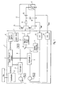
- Fig. 1 is shown schematically a digital circuit 1 for controlling the power of a connected light source.
- This digital circuit 1 is part of a control gear for the bulbs.
- the invention will be explained with reference to an electronic ballast as an example of an operating device and to a gas discharge lamp as an example of a light source. However, the invention can also be applied to other dimmable control gear and lamps
- the digital circuit 1 generates control signals for the two electronic switches (FETs) of an inverter 14, by means of which an applied DC supply voltage V z (intermediate circuit voltage) can be converted into an adjustable-frequency AC voltage which is tapped at the midpoint of the inverter 14 , At this midpoint of the inverter 14, an RC circuit with an inductor 13 and a capacitor 18 are provided in a known manner, to which a coupling capacitor 16 to the lamp 17 is connected in parallel. Symbolic is in Fig. 1 shown that the lamp 17 can be electrically reproduced as a variable impedance resistor.
- a signal S IMP which directly or indirectly represents the lamp impedance.
- S pow is a signal indicating the lamp power.
- the lamp power can be reproduced for example by the lamp voltage, the lamp current or else the light power (detected, for example, via photodetectors).
- the feedback signals S IMP , S pow supplied to the digital control circuit 1 thus represent actual values of the lamp operation and are digitized by AD converters 19, 20.
- the digitized actual value of the lamp power reproducing signal S pow is compared with a first reference voltage V ref1 .
- This reference voltage represents an internal setpoint. As in FIG. 1 illustrated by a dashed line, but this setpoint may depend in particular on an externally supplied Dimmwert. In any case, the result of the comparison actual value / setpoint represents the control error e (k), which is supplied to a first digital controller 4.
- the digital controller is preferably implemented purely in software, wherein the A / D-converted signals can be fed directly to this software controller. This allows for increased processing speed and faster response to changes compared to caching.
- the purely digital version allows a high flexibility of the controller properties.
- a control algorithm is implemented in a digital manner, which generates a control signal 8, depending on the input signal supplied, by means of the corresponding position of a electronic switch 10 (FET, etc.) an inverter driver 12 is driven, so that the output signal (control signal y (k)) of the controller 4 indicates the operating frequency of the inverter 14 and the operating frequency of the inverter 14 again due to the known resonance curve of a gas discharge lamp 17 Indicates lamp power.
- control branch using an inverter 14 in which the control variable that is the frequency of the switches of the inverter 14, is only an example.
- control variables such as light source etc , which can be used at any time in connection with the present invention.
- the digital circuit 1 has a system controller 2, which processes a program stored as a firmware.
- the system controller 2 is connected to a system memory 6 and is clocked by a system clock (system clock) 7.
- the system controller 2 is connected to an interface 3, the dimming signals from the outside, for example, be fed from a bus line forth.
- the external dimming signals may be analog and / or digital, in any case, the interface 3 transmits to the system controller 2 digital values that reflect the applied dimming signals.
- the system controller 2 is, for example, firmware configured such that it adjusts properties of the controller 4 as a function of the digital values supplied by the interface 3, which thus reproduce the external dimming signals.
- properties of the controller 4 can be assigned to certain dimming values, so the system controller 2 can read out the properties required for the application of a specific dimming value from the system memory 6 and set the controller 4 accordingly.
- the controller 4 has properties that can be set on the system controller 2 depending on externally supplied dimming signals.
- Fig. 1 can be provided for a further feedback signal as the actual size, for example, the lamp impedance S IMP a second controller 5.
- these regulator 5 are supplied with digitized values directly from the AC converter 19, which thus represent a signal which directly or indirectly reproduces the current lamp impedance S IMP .
- the controller 5 Similar to the controller 4, the controller 5 also generates a control signal 9 in accordance with the control algorithm implemented digitally in dependence on a comparison of the actual impedance with a setpoint value for the impedance, which is reproduced in the form of a voltage V REF2 .
- the electronic switch 10 is driven and thus selected whether the control signal 8 from the first digital controller 4 or the control signal 9 from the second controller 5 is to be used as the actual input signal for the inverter driver 12.
- the switch controller 11 can adjust the electronic switch 10 depending on the current value of the digitized signal S IMP reproducing the lamp impedance. For example, it may be provided that the switch controller 11 only activates the switch 10 for the use of the second regulator 5 when the currently applied signal S IMP representing the lamp impedance is above a predetermined threshold value. So if the signal impedance directly or indirectly representing the lamp impedance S IMP (in digital form) over one is set, a regulation using the lamp impedance S IMP as a feedback variable, while otherwise, that is, when the lamp impedance is below a predetermined limit, is controlled to the lamp power reproducing signal S pow as feedback and actual value.
- the properties of the second controller 5 can be set by the system controller 2 in a comparable manner to the first controller 4 as a function of applied dimming values.
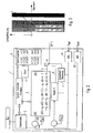
- Fig. 2 schematically shows that in the system memory 6 coefficients are stored for the digital control algorithm.
- the controller 4 and optionally also the controller 5 generate an output signal y (k) depending on an input signal e (k) and possibly also the value of the input signal not only to the currently present time step K, but also previous time steps k-1, k-2, ...
- the control signal y (k) can thus be calculated using a linear combination consisting of so-called control coefficients a11, a21,... Of the control difference e (k) present at the current time step K and a series of control differences for preceding time steps e (k-1). , e (k-2), ...
- the dynamic behavior of the so-called controlled system i. the lighting means together with the output circuit of the upstream electronics (eg ballast) usually determines the choice of suitable control coefficients. These are chosen so that the closed loop reacts quickly but also stably to changes in the input or to disturbances.
- the current operating state can be measured (for example, based on the lamp current and / or the lamp voltage) or estimated from the time elapsed since the ignition.
- the properties of the digital implementation of the control algorithm are set in software depending on the currently set dimming value, which can be done by the system controller 1 using the coefficients from the system memory 6, as explained above.
- control coefficients a11, a21, etc. can be changed relatively easily by control signals from the system controller 1.
- a comparable analog system would need to switch between different hardware elements, which is complicated and costly and also affects the accuracy of the system.
- the control properties can be changed such that the type of the selected feedback variable is changed as the actual value. For example, it may be provided that it is then no longer the signal S pow reproducing the lamp power, but another measured variable, such as the impedance of the lamp S IMP, used as the feedback variable to ensure stable operation of the lamp.
- the values and the number of control coefficients can also be changed at the same time. For this purpose, as mentioned, switching to a second controller 5 may be advantageous.
- the digital control circuit 1 may also be implemented in hardware, software, programmable logic, or any combination thereof.
Landscapes
- Discharge-Lamp Control Circuits And Pulse- Feed Circuits (AREA)
- Circuit Arrangement For Electric Light Sources In General (AREA)
Claims (9)
- Procédé pour une régulation de la puissance d'un moyen d'éclairage (17),
dans lequel un paramètre représentant la puissance du moyen d'éclairage (17) est envoyé en rétroaction en tant que valeur réelle et est comparé à une valeur de consigne pour la puissance de la lampe, et une valeur de commande, qui dépend de la comparaison de la valeur de consigne et de la valeur réelle, pour la puissance de la lampe est calculée selon une implémentation numérique, dans lequel- la valeur de consigne est fournie en tant que signal de gradation externe, et- des propriétés dynamiques de la régulation de la puissance sont modifiées en fonction de la valeur du signal de gradation actuellement appliqué, dans lequel, en fonction d'une variable de mesure concernant le moyen d'éclairage (17), il y a un passage de la puissance du moyen d'éclairage à une autre variable physique en tant que valeur réelle envoyée en rétroaction. - Procédé selon la revendication 1,
dans lequel un algorithme, qui est mis en oeuvre numériquement pour la régulation de la puissance, utilise des coefficients de régulation, qui sont modifiés en fonction de la valeur du signal de gradation actuellement appliqué. - Procédé selon la revendication 2,
dans lequel des constantes de temps de l'algorithme mis en oeuvre numériquement sont modifiées en fonction de la valeur du signal de gradation appliqué actuellement. - Procédé selon l'une des revendications précédentes,
dans lequel une lampe à décharge de gaz est utilisée en tant que moyen d'éclairage, sa puissance étant commandée par l'intermédiaire de l'ajustement de la fréquence d'une tension d'alimentation fournie à la lampe à décharge de gaz. - Procédé selon la revendication 1,
dans lequel la variable de mesure est la valeur de gradation et/ou la température du moyen d'éclairage. - Procédé selon la revendication 1 ou 5,
dans lequel l'autre variable physique est l'impédance du moyen d'éclairage détectée directement ou indirectement. - Produit programme d'ordinateur,
qui réalise un procédé de régulation numérique selon l'une des revendications précédentes, lorsqu'il fonctionne dans un dispositif de calcul. - Circuit numérique (1), qui est configuré pour exécuter un procédé selon l'une des revendications précédentes.
- Appareil de commande pour moyen d'éclairage (17) comprenant un circuit (1) selon la revendication 8.
Applications Claiming Priority (2)
| Application Number | Priority Date | Filing Date | Title |
|---|---|---|---|
| DE200510018774 DE102005018774A1 (de) | 2005-04-22 | 2005-04-22 | Einstellbare digitale Leuchtmittelleistungsregelung |
| PCT/EP2006/003757 WO2006111422A1 (fr) | 2005-04-22 | 2006-04-24 | Reglage numerique variable de la puissance d'un moyen d'eclairage |
Publications (2)
| Publication Number | Publication Date |
|---|---|
| EP1872636A1 EP1872636A1 (fr) | 2008-01-02 |
| EP1872636B1 true EP1872636B1 (fr) | 2013-11-13 |
Family
ID=36748382
Family Applications (1)
| Application Number | Title | Priority Date | Filing Date |
|---|---|---|---|
| EP06742658.5A Expired - Lifetime EP1872636B1 (fr) | 2005-04-22 | 2006-04-24 | Reglage numerique variable de la puissance d'un moyen d'eclairage |
Country Status (5)
| Country | Link |
|---|---|
| EP (1) | EP1872636B1 (fr) |
| CN (1) | CN101164387A (fr) |
| AU (1) | AU2006237227B2 (fr) |
| DE (1) | DE102005018774A1 (fr) |
| WO (1) | WO2006111422A1 (fr) |
Families Citing this family (2)
| Publication number | Priority date | Publication date | Assignee | Title |
|---|---|---|---|---|
| US8664894B2 (en) | 2009-12-08 | 2014-03-04 | Koninklijke Philips N.V. | Method and device for driving a fluorescent lamp |
| CN102438381B (zh) * | 2011-09-29 | 2013-12-04 | 林建辉 | 一种高速车辆客室内照度模拟系统的实现方法 |
Family Cites Families (4)
| Publication number | Priority date | Publication date | Assignee | Title |
|---|---|---|---|---|
| DE4018127A1 (de) * | 1990-06-06 | 1991-12-12 | Zumtobel Ag | Verfahren und schaltungsanordnung zur regelung der helligkeit (dimmen) von gasentladungslampen |
| DE4039161C2 (de) * | 1990-12-07 | 2001-05-31 | Zumtobel Ag Dornbirn | System zur Steuerung der Helligkeit und des Betriebsverhaltens von Leuchtstofflampen |
| DE19708783C1 (de) * | 1997-03-04 | 1998-10-08 | Tridonic Bauelemente | Verfahren und Vorrichtung zum Regeln des Betriebsverhaltens von Gasentladungslampen |
| DE19748007A1 (de) * | 1997-10-30 | 1999-05-12 | Tridonic Bauelemente | Schnittstelle für ein Lampenbetriebsgerät |
-
2005
- 2005-04-22 DE DE200510018774 patent/DE102005018774A1/de not_active Withdrawn
-
2006
- 2006-04-24 EP EP06742658.5A patent/EP1872636B1/fr not_active Expired - Lifetime
- 2006-04-24 CN CNA2006800130051A patent/CN101164387A/zh active Pending
- 2006-04-24 AU AU2006237227A patent/AU2006237227B2/en not_active Ceased
- 2006-04-24 WO PCT/EP2006/003757 patent/WO2006111422A1/fr not_active Ceased
Also Published As
| Publication number | Publication date |
|---|---|
| WO2006111422A1 (fr) | 2006-10-26 |
| EP1872636A1 (fr) | 2008-01-02 |
| CN101164387A (zh) | 2008-04-16 |
| AU2006237227A1 (en) | 2006-10-26 |
| AU2006237227B2 (en) | 2010-02-04 |
| DE102005018774A1 (de) | 2006-10-26 |
Similar Documents
| Publication | Publication Date | Title |
|---|---|---|
| DE112009002486B4 (de) | Adaptiver PFC für Leuchtmittel-Lastkreis, insbesondere Lastkreis mit LED | |
| DE112012003656B4 (de) | Treiberschaltung und verfahren zum treiben einer elektrischen last | |
| EP2548409B1 (fr) | Commande d'une chaîne de diodes électroluminescentes par une surce de courant constante commutée | |
| EP1872627B1 (fr) | Pfc numerique parametrable | |
| DE19708783C1 (de) | Verfahren und Vorrichtung zum Regeln des Betriebsverhaltens von Gasentladungslampen | |
| DE102014106869B4 (de) | LED-Beleuchtungsvorrichtung und Beleuchtungsgerät | |
| DE19708791A1 (de) | Steuerschaltung und elektronisches Vorschaltgerät mit einer derartigen Steuerschaltung | |
| EP3334252B1 (fr) | Unité d'éclairage linéaire ainsi que son procédé de gradation de la luminosité | |
| DE10127783A1 (de) | Endladungslampenansteuergerät | |
| EP1872636B1 (fr) | Reglage numerique variable de la puissance d'un moyen d'eclairage | |
| EP3064038B1 (fr) | Circuit de commande d'élément luminescent comportant un convertisseur cadencé pour le réglage numérique d'une température de couleur et/ou d'un niveau de variation d'intensité lumineuse | |
| EP2256927B1 (fr) | Etalonnage et commande d'amorçage des interrupteurs dans un équipement d'exploitation pour des éléments lumineux | |
| DE202009001708U1 (de) | Niedervolt Beleuchtungssystem und Regelschaltung zur Verwendung in einem Niedervolt Beleuchtungssystem | |
| WO2006114176A1 (fr) | Reglage numerique variable de la puissance d'un moyen d'eclairage | |
| EP1400156B1 (fr) | Equipement pour tubes fluorescents avec dissipateur incorpore | |
| DE102015114324A1 (de) | Präzise Amplitudendimmen der LEDs | |
| EP2452543B1 (fr) | Procédé pour faire fonctionner des lampes à décharge de gaz à des températures extérieures basses et appareil de fonctionnement conçu à cet effet | |
| WO2019020357A1 (fr) | Agencement de circuit et procédé de détermination d'un signal représentant une valeur d'intensité réelle | |
| EP2474206B1 (fr) | Correction de cosinus (phi) dans des ballasts à régulation du courant ou de la puissance pour des lampes | |
| EP1555858A2 (fr) | Alimentation centrale pour l'alimentation de lampes contenant un circuit convertisseur de correction du facteur de puissance | |
| EP2425684B1 (fr) | Circuit de ballast régulé en puissance pour un luminaire, et procédé de fonctionnement | |
| WO2014172734A1 (fr) | Circuit pour faire fonctionner des diodes électroluminescentes | |
| EP1908337B2 (fr) | Regulation adaptative de la puissance de lampes a decharge gazeuse | |
| EP1324643B1 (fr) | Ballast électronique avec protection en température | |
| EP1932398B1 (fr) | Chauffage de filament variable |
Legal Events
| Date | Code | Title | Description |
|---|---|---|---|
| PUAI | Public reference made under article 153(3) epc to a published international application that has entered the european phase |
Free format text: ORIGINAL CODE: 0009012 |
|
| 17P | Request for examination filed |
Effective date: 20070914 |
|
| AK | Designated contracting states |
Kind code of ref document: A1 Designated state(s): AT BE BG CH CY CZ DE DK EE ES FI FR GB GR HU IE IS IT LI LT LU LV MC NL PL PT RO SE SI SK TR |
|
| 17Q | First examination report despatched |
Effective date: 20080313 |
|
| DAX | Request for extension of the european patent (deleted) | ||
| RAP1 | Party data changed (applicant data changed or rights of an application transferred) |
Owner name: TRIDONIC GMBH & CO KG |
|
| GRAP | Despatch of communication of intention to grant a patent |
Free format text: ORIGINAL CODE: EPIDOSNIGR1 |
|
| INTG | Intention to grant announced |
Effective date: 20130605 |
|
| GRAS | Grant fee paid |
Free format text: ORIGINAL CODE: EPIDOSNIGR3 |
|
| GRAA | (expected) grant |
Free format text: ORIGINAL CODE: 0009210 |
|
| AK | Designated contracting states |
Kind code of ref document: B1 Designated state(s): AT BE BG CH CY CZ DE DK EE ES FI FR GB GR HU IE IS IT LI LT LU LV MC NL PL PT RO SE SI SK TR |
|
| REG | Reference to a national code |
Ref country code: GB Ref legal event code: FG4D Free format text: NOT ENGLISH |
|
| REG | Reference to a national code |
Ref country code: CH Ref legal event code: EP |
|
| REG | Reference to a national code |
Ref country code: AT Ref legal event code: REF Ref document number: 641025 Country of ref document: AT Kind code of ref document: T Effective date: 20131215 |
|
| REG | Reference to a national code |
Ref country code: IE Ref legal event code: FG4D Free format text: LANGUAGE OF EP DOCUMENT: GERMAN |
|
| REG | Reference to a national code |
Ref country code: DE Ref legal event code: R096 Ref document number: 502006013347 Country of ref document: DE Effective date: 20140102 |
|
| REG | Reference to a national code |
Ref country code: NL Ref legal event code: VDEP Effective date: 20131113 |
|
| REG | Reference to a national code |
Ref country code: LT Ref legal event code: MG4D |
|
| PG25 | Lapsed in a contracting state [announced via postgrant information from national office to epo] |
Ref country code: SE Free format text: LAPSE BECAUSE OF FAILURE TO SUBMIT A TRANSLATION OF THE DESCRIPTION OR TO PAY THE FEE WITHIN THE PRESCRIBED TIME-LIMIT Effective date: 20131113 Ref country code: FI Free format text: LAPSE BECAUSE OF FAILURE TO SUBMIT A TRANSLATION OF THE DESCRIPTION OR TO PAY THE FEE WITHIN THE PRESCRIBED TIME-LIMIT Effective date: 20131113 Ref country code: LT Free format text: LAPSE BECAUSE OF FAILURE TO SUBMIT A TRANSLATION OF THE DESCRIPTION OR TO PAY THE FEE WITHIN THE PRESCRIBED TIME-LIMIT Effective date: 20131113 Ref country code: NL Free format text: LAPSE BECAUSE OF FAILURE TO SUBMIT A TRANSLATION OF THE DESCRIPTION OR TO PAY THE FEE WITHIN THE PRESCRIBED TIME-LIMIT Effective date: 20131113 Ref country code: IS Free format text: LAPSE BECAUSE OF FAILURE TO SUBMIT A TRANSLATION OF THE DESCRIPTION OR TO PAY THE FEE WITHIN THE PRESCRIBED TIME-LIMIT Effective date: 20140313 |
|
| PG25 | Lapsed in a contracting state [announced via postgrant information from national office to epo] |
Ref country code: CY Free format text: LAPSE BECAUSE OF FAILURE TO SUBMIT A TRANSLATION OF THE DESCRIPTION OR TO PAY THE FEE WITHIN THE PRESCRIBED TIME-LIMIT Effective date: 20131113 Ref country code: ES Free format text: LAPSE BECAUSE OF FAILURE TO SUBMIT A TRANSLATION OF THE DESCRIPTION OR TO PAY THE FEE WITHIN THE PRESCRIBED TIME-LIMIT Effective date: 20131113 Ref country code: LV Free format text: LAPSE BECAUSE OF FAILURE TO SUBMIT A TRANSLATION OF THE DESCRIPTION OR TO PAY THE FEE WITHIN THE PRESCRIBED TIME-LIMIT Effective date: 20131113 |
|
| PG25 | Lapsed in a contracting state [announced via postgrant information from national office to epo] |
Ref country code: PT Free format text: LAPSE BECAUSE OF FAILURE TO SUBMIT A TRANSLATION OF THE DESCRIPTION OR TO PAY THE FEE WITHIN THE PRESCRIBED TIME-LIMIT Effective date: 20140313 |
|
| PG25 | Lapsed in a contracting state [announced via postgrant information from national office to epo] |
Ref country code: EE Free format text: LAPSE BECAUSE OF FAILURE TO SUBMIT A TRANSLATION OF THE DESCRIPTION OR TO PAY THE FEE WITHIN THE PRESCRIBED TIME-LIMIT Effective date: 20131113 |
|
| REG | Reference to a national code |
Ref country code: DE Ref legal event code: R097 Ref document number: 502006013347 Country of ref document: DE |
|
| PG25 | Lapsed in a contracting state [announced via postgrant information from national office to epo] |
Ref country code: RO Free format text: LAPSE BECAUSE OF FAILURE TO SUBMIT A TRANSLATION OF THE DESCRIPTION OR TO PAY THE FEE WITHIN THE PRESCRIBED TIME-LIMIT Effective date: 20131113 Ref country code: PL Free format text: LAPSE BECAUSE OF FAILURE TO SUBMIT A TRANSLATION OF THE DESCRIPTION OR TO PAY THE FEE WITHIN THE PRESCRIBED TIME-LIMIT Effective date: 20131113 Ref country code: CZ Free format text: LAPSE BECAUSE OF FAILURE TO SUBMIT A TRANSLATION OF THE DESCRIPTION OR TO PAY THE FEE WITHIN THE PRESCRIBED TIME-LIMIT Effective date: 20131113 Ref country code: SK Free format text: LAPSE BECAUSE OF FAILURE TO SUBMIT A TRANSLATION OF THE DESCRIPTION OR TO PAY THE FEE WITHIN THE PRESCRIBED TIME-LIMIT Effective date: 20131113 |
|
| PGFP | Annual fee paid to national office [announced via postgrant information from national office to epo] |
Ref country code: AT Payment date: 20140424 Year of fee payment: 9 |
|
| PLBE | No opposition filed within time limit |
Free format text: ORIGINAL CODE: 0009261 |
|
| STAA | Information on the status of an ep patent application or granted ep patent |
Free format text: STATUS: NO OPPOSITION FILED WITHIN TIME LIMIT |
|
| PG25 | Lapsed in a contracting state [announced via postgrant information from national office to epo] |
Ref country code: DK Free format text: LAPSE BECAUSE OF FAILURE TO SUBMIT A TRANSLATION OF THE DESCRIPTION OR TO PAY THE FEE WITHIN THE PRESCRIBED TIME-LIMIT Effective date: 20131113 |
|
| 26N | No opposition filed |
Effective date: 20140814 |
|
| REG | Reference to a national code |
Ref country code: DE Ref legal event code: R097 Ref document number: 502006013347 Country of ref document: DE Effective date: 20140814 |
|
| PG25 | Lapsed in a contracting state [announced via postgrant information from national office to epo] |
Ref country code: MC Free format text: LAPSE BECAUSE OF FAILURE TO SUBMIT A TRANSLATION OF THE DESCRIPTION OR TO PAY THE FEE WITHIN THE PRESCRIBED TIME-LIMIT Effective date: 20131113 Ref country code: LU Free format text: LAPSE BECAUSE OF FAILURE TO SUBMIT A TRANSLATION OF THE DESCRIPTION OR TO PAY THE FEE WITHIN THE PRESCRIBED TIME-LIMIT Effective date: 20140424 |
|
| REG | Reference to a national code |
Ref country code: CH Ref legal event code: PL |
|
| REG | Reference to a national code |
Ref country code: IE Ref legal event code: MM4A |
|
| PG25 | Lapsed in a contracting state [announced via postgrant information from national office to epo] |
Ref country code: LI Free format text: LAPSE BECAUSE OF NON-PAYMENT OF DUE FEES Effective date: 20140430 Ref country code: CH Free format text: LAPSE BECAUSE OF NON-PAYMENT OF DUE FEES Effective date: 20140430 |
|
| PG25 | Lapsed in a contracting state [announced via postgrant information from national office to epo] |
Ref country code: SI Free format text: LAPSE BECAUSE OF FAILURE TO SUBMIT A TRANSLATION OF THE DESCRIPTION OR TO PAY THE FEE WITHIN THE PRESCRIBED TIME-LIMIT Effective date: 20131113 |
|
| PG25 | Lapsed in a contracting state [announced via postgrant information from national office to epo] |
Ref country code: IT Free format text: LAPSE BECAUSE OF FAILURE TO SUBMIT A TRANSLATION OF THE DESCRIPTION OR TO PAY THE FEE WITHIN THE PRESCRIBED TIME-LIMIT Effective date: 20131113 |
|
| PG25 | Lapsed in a contracting state [announced via postgrant information from national office to epo] |
Ref country code: IE Free format text: LAPSE BECAUSE OF NON-PAYMENT OF DUE FEES Effective date: 20140424 |
|
| REG | Reference to a national code |
Ref country code: AT Ref legal event code: MM01 Ref document number: 641025 Country of ref document: AT Kind code of ref document: T Effective date: 20150424 |
|
| PG25 | Lapsed in a contracting state [announced via postgrant information from national office to epo] |
Ref country code: AT Free format text: LAPSE BECAUSE OF NON-PAYMENT OF DUE FEES Effective date: 20150424 |
|
| REG | Reference to a national code |
Ref country code: FR Ref legal event code: PLFP Year of fee payment: 11 |
|
| PG25 | Lapsed in a contracting state [announced via postgrant information from national office to epo] |
Ref country code: BG Free format text: LAPSE BECAUSE OF FAILURE TO SUBMIT A TRANSLATION OF THE DESCRIPTION OR TO PAY THE FEE WITHIN THE PRESCRIBED TIME-LIMIT Effective date: 20131113 |
|
| PG25 | Lapsed in a contracting state [announced via postgrant information from national office to epo] |
Ref country code: GR Free format text: LAPSE BECAUSE OF FAILURE TO SUBMIT A TRANSLATION OF THE DESCRIPTION OR TO PAY THE FEE WITHIN THE PRESCRIBED TIME-LIMIT Effective date: 20140214 |
|
| PG25 | Lapsed in a contracting state [announced via postgrant information from national office to epo] |
Ref country code: BE Free format text: LAPSE BECAUSE OF FAILURE TO SUBMIT A TRANSLATION OF THE DESCRIPTION OR TO PAY THE FEE WITHIN THE PRESCRIBED TIME-LIMIT Effective date: 20140430 Ref country code: TR Free format text: LAPSE BECAUSE OF FAILURE TO SUBMIT A TRANSLATION OF THE DESCRIPTION OR TO PAY THE FEE WITHIN THE PRESCRIBED TIME-LIMIT Effective date: 20131113 Ref country code: HU Free format text: LAPSE BECAUSE OF FAILURE TO SUBMIT A TRANSLATION OF THE DESCRIPTION OR TO PAY THE FEE WITHIN THE PRESCRIBED TIME-LIMIT; INVALID AB INITIO Effective date: 20060424 |
|
| PGFP | Annual fee paid to national office [announced via postgrant information from national office to epo] |
Ref country code: GB Payment date: 20160502 Year of fee payment: 11 |
|
| PGFP | Annual fee paid to national office [announced via postgrant information from national office to epo] |
Ref country code: FR Payment date: 20160427 Year of fee payment: 11 |
|
| PGFP | Annual fee paid to national office [announced via postgrant information from national office to epo] |
Ref country code: DE Payment date: 20160630 Year of fee payment: 11 |
|
| REG | Reference to a national code |
Ref country code: DE Ref legal event code: R119 Ref document number: 502006013347 Country of ref document: DE |
|
| GBPC | Gb: european patent ceased through non-payment of renewal fee |
Effective date: 20170424 |
|
| REG | Reference to a national code |
Ref country code: FR Ref legal event code: ST Effective date: 20171229 |
|
| PG25 | Lapsed in a contracting state [announced via postgrant information from national office to epo] |
Ref country code: DE Free format text: LAPSE BECAUSE OF NON-PAYMENT OF DUE FEES Effective date: 20171103 Ref country code: FR Free format text: LAPSE BECAUSE OF NON-PAYMENT OF DUE FEES Effective date: 20170502 |
|
| PG25 | Lapsed in a contracting state [announced via postgrant information from national office to epo] |
Ref country code: GB Free format text: LAPSE BECAUSE OF NON-PAYMENT OF DUE FEES Effective date: 20170424 |