EP1872723A1 - Système et procédé à ultrasons pour former une image ultrasonore - Google Patents
Système et procédé à ultrasons pour former une image ultrasonore Download PDFInfo
- Publication number
- EP1872723A1 EP1872723A1 EP20070012555 EP07012555A EP1872723A1 EP 1872723 A1 EP1872723 A1 EP 1872723A1 EP 20070012555 EP20070012555 EP 20070012555 EP 07012555 A EP07012555 A EP 07012555A EP 1872723 A1 EP1872723 A1 EP 1872723A1
- Authority
- EP
- European Patent Office
- Prior art keywords
- roi
- image
- plane
- volume data
- information
- Prior art date
- Legal status (The legal status is an assumption and is not a legal conclusion. Google has not performed a legal analysis and makes no representation as to the accuracy of the status listed.)
- Withdrawn
Links
Images




Classifications
-
- A—HUMAN NECESSITIES
- A61—MEDICAL OR VETERINARY SCIENCE; HYGIENE
- A61B—DIAGNOSIS; SURGERY; IDENTIFICATION
- A61B8/00—Diagnosis using ultrasonic, sonic or infrasonic waves
- A61B8/13—Tomography
- A61B8/14—Echo-tomography
-
- A—HUMAN NECESSITIES
- A61—MEDICAL OR VETERINARY SCIENCE; HYGIENE
- A61B—DIAGNOSIS; SURGERY; IDENTIFICATION
- A61B8/00—Diagnosis using ultrasonic, sonic or infrasonic waves
-
- A—HUMAN NECESSITIES
- A61—MEDICAL OR VETERINARY SCIENCE; HYGIENE
- A61B—DIAGNOSIS; SURGERY; IDENTIFICATION
- A61B8/00—Diagnosis using ultrasonic, sonic or infrasonic waves
- A61B8/13—Tomography
-
- A—HUMAN NECESSITIES
- A61—MEDICAL OR VETERINARY SCIENCE; HYGIENE
- A61B—DIAGNOSIS; SURGERY; IDENTIFICATION
- A61B8/00—Diagnosis using ultrasonic, sonic or infrasonic waves
- A61B8/46—Ultrasonic, sonic or infrasonic diagnostic devices with special arrangements for interfacing with the operator or the patient
- A61B8/461—Displaying means of special interest
- A61B8/463—Displaying means of special interest characterised by displaying multiple images or images and diagnostic data on one display
-
- A—HUMAN NECESSITIES
- A61—MEDICAL OR VETERINARY SCIENCE; HYGIENE
- A61B—DIAGNOSIS; SURGERY; IDENTIFICATION
- A61B8/00—Diagnosis using ultrasonic, sonic or infrasonic waves
- A61B8/46—Ultrasonic, sonic or infrasonic diagnostic devices with special arrangements for interfacing with the operator or the patient
- A61B8/461—Displaying means of special interest
- A61B8/466—Displaying means of special interest adapted to display 3D data
-
- A—HUMAN NECESSITIES
- A61—MEDICAL OR VETERINARY SCIENCE; HYGIENE
- A61B—DIAGNOSIS; SURGERY; IDENTIFICATION
- A61B8/00—Diagnosis using ultrasonic, sonic or infrasonic waves
- A61B8/46—Ultrasonic, sonic or infrasonic diagnostic devices with special arrangements for interfacing with the operator or the patient
- A61B8/467—Ultrasonic, sonic or infrasonic diagnostic devices with special arrangements for interfacing with the operator or the patient characterised by special input means
-
- A—HUMAN NECESSITIES
- A61—MEDICAL OR VETERINARY SCIENCE; HYGIENE
- A61B—DIAGNOSIS; SURGERY; IDENTIFICATION
- A61B8/00—Diagnosis using ultrasonic, sonic or infrasonic waves
- A61B8/46—Ultrasonic, sonic or infrasonic diagnostic devices with special arrangements for interfacing with the operator or the patient
- A61B8/467—Ultrasonic, sonic or infrasonic diagnostic devices with special arrangements for interfacing with the operator or the patient characterised by special input means
- A61B8/469—Ultrasonic, sonic or infrasonic diagnostic devices with special arrangements for interfacing with the operator or the patient characterised by special input means for selection of a region of interest
-
- A—HUMAN NECESSITIES
- A61—MEDICAL OR VETERINARY SCIENCE; HYGIENE
- A61B—DIAGNOSIS; SURGERY; IDENTIFICATION
- A61B8/00—Diagnosis using ultrasonic, sonic or infrasonic waves
- A61B8/48—Diagnostic techniques
- A61B8/483—Diagnostic techniques involving the acquisition of a 3D volume of data
Definitions
- the present invention generally relates to an ultrasound system, and more particularly to an ultrasound system and a method for forming an ultrasound image.
- An ultrasound system has become an important and popular diagnostic tool since it has a wide range of applications. Specifically, due to its non-invasive and nondestructive nature, the ultrasound system has been extensively used in the medical profession. Modern high-performance ultrasound diagnostic systems and techniques are commonly used to produce two or three-dimensional (2D or 3D) ultrasound images of internal features of an object (e.g., human organs).
- an object e.g., human organs.
- the ultrasound system transmits ultrasound signals to the target object and then receives ultrasound echo signals.
- the ultrasound system forms volume data of the target object based on the received ultrasound echo signals.
- plane selection information for selecting a specific plane from the volume data is inputted through an input unit, the ultrasound system extracts data corresponding to the selected plane from the volume data.
- the ultrasound system forms a plane image (2D image) based on the extracted data to be displayed through a display unit.
- the ultrasound system sets the ROI on the 2D image based on the ROI setting information.
- the ultrasound system extracts data corresponding to the ROI from the volume data and then renders the extracted data, thereby forming the 3D image.
- the 3D image is displayed together with the 2D image corresponding to ROI on the display unit.
- a need may arise to reset the ROI for displaying 2D and 3D images corresponding to a different portion of the target object.
- ROI reset information is received through the input unit, the ultrasound system resets the ROI on the 2D image based on the ROI reset information.
- a display mode displaying the 2D image together with the 3D image should be changed to a single display mode because the ROI setting can be carried out only at the single display mode for displaying only one 2D image in the conventional ultrasound system. That is, a multi display mode for displaying the 3D image together with the 2D image should be changed to the single display mode. Therefore, since the display mode has to be changed to reset the ROI, there are problems that it is inconvenient to reset the ROI, and an amount of time needed for diagnosis increases.
- FIG. 1 is a schematic block diagram illustrating an ultrasound diagnostic device constructed in accordance with one embodiment of the present invention
- FIG. 2 is a flowchart illustrating a method of forming an ultrasound image in accordance with one embodiment of the present invention
- FIG. 3 is a schematic diagram showing an example of volume data and reference planes.
- FIGS. 4 to 7 are diagrams showing examples of displaying ultrasound images in accordance with the present invention.
- FIG. 1 is a block diagram illustrating an ultrasound system, which is constructed in accordance with the present invention.
- the ultrasound system 100 includes a diagnosis unit 110, a volume data forming unit 120, a storing unit 130, a processor 140, a display unit 150 and a control unit 160.
- the ultrasound system 100 may further include an input unit (e.g., mouse, track ball, key board, touch pad, etc.) for receiving region of interest (ROI) setting information for setting a ROI from a user.
- ROI region of interest
- the diagnosis unit 110 includes a probe and a beam former (not shown).
- the probe contains a plurality of transducer elements for reciprocally converting electric signals and ultrasound signals.
- the probe transmits ultrasound signals to a target object and receives ultrasound echo signals reflected from the target object.
- the probe converts the received ultrasound echo signals into electric signals (Hereinafter, referred to as receive signals).
- the beam former applies delays to the receive signals, thereby producing focused receive signals.
- the volume data forming unit 120 forms volume data based on the focused receive signals outputted from the diagnosis unit 110.
- the volume data may be stored in the storage unit 130.
- the processor 140 extracts data corresponding to the selected reference plane from the volume data stored in the storage unit 130.
- the processor 140 performs image signal processing based on the extracted data to form an image signal corresponding to the selected reference plane.
- a reference plane image is formed based on the image signal.
- the reference plane may be one of A, B and C planes in the volume data 210 as shown in Fig. 3.
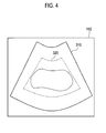
- the processor 140 sets ROI 320 on the reference plane image 310 as shown in FIG. 4 and then extracts data corresponding to the ROI 320 from the volume data.
- the processor 140 performs image signal processing based on the extracted data, thereby forming a ROI image signal and a 3D image signal corresponding to the ROI.
- the display unit 150 receives the reference plane image signal, the ROI image signal and the 3D image signal to display the reference plane image, a ROI image and a 3D image on a display region. If a single display mode is selected in the ultrasound system, the display region is used to display one image. On the contrary, if a multi display mode is selected in the ultrasound system, the display region of the display 150 may be partitioned into a plurality of sub display regions, wherein each sub display region displays one of the reference plane image, the ROI image and the 3D image. For instance, the display region of the display unit 150 may be partitioned into a first sub display region and a second sub display region at the multi display mode. In this case, the ROI image may be displayed on the first sub display region and the 3D image may be displayed on the second sub display region.
- the control unit 160 may control the processor 140 to extract the data corresponding to the ROI from the volume data stored in the storage unit 130 in response to the ROI setting information.
- the ROI setting information may include information associated with a size and a position of the ROI.
- the control unit 160 may control the partitioning of the display region of the display unit 150 according to the display mode. Further, the control unit 160 may check whether ROI reset information is inputted through the input unit. If the ROI reset information is inputted, the control unit 160 controls the display unit 150 such that the reference plane image is displayed on the first sub display region instead of displaying the ROI image. Therefore, if new ROI setting information is inputted, the new ROI may be set on the reference plane image displayed on the first sub display region while the 3D image is displayed on the second sub display region.
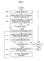
- FIG. 2 is a flowchart showing a process for forming ultrasound images in accordance with one embodiment of the present invention.
- the volume data forming unit 120 forms volume data based on ultrasound echo signals received at the diagnosis unit 110 and the volume data are stored in the storage unit as step S102. If reference selection information is inputted, the processor 140 extracts data corresponding to a reference planes selected based on the plane selection information from the volume data and then performs image signal processing based on the extracted data, thereby forming a reference plane image signal at step S104.
- the display unit 150 receives the reference plane image signal from the processor 140 to display a reference plane image 310 on a display region 152 as shown in FIG. 4 at step S106.
- the control unit 160 checks whether the ROI setting information is inputted through the input unit at step S108. If the ROI setting information is not inputted, the control unit 160 stands by until the ROI setting information is inputted.
- the processor 140 sets the ROI 320 on the reference plane image 310 based on the ROI setting information and extracts data corresponding to the ROI 320 from the volume data stored in the storage unit 130 at step S110.
- the processor 140 performs image signal processing based on the extracted data, thereby forming a ROI image signal and a 3D image signal corresponding to the ROI 320 at step S112.
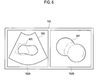
- the display unit 150 receives the ROI image signal and the 3D image signal to display a ROI image 331 and a 3D image 341 on the first and second sub display regions 152A and 152B, respectively, at the same time as shown in FIG. 5 at step S 114.
- the control unit 160 checks whether ROI reset information for resetting ROI is inputted through the input unit in real time at step S116. If the ROI reset information is not inputted, the process goes to step S126. On the other hand, if it is determined that the ROI reset information is inputted, the control unit 160 may control to the reference plane image to be displayed on the first sub display region 152A instead of displaying the ROI image at step S118. The processor 140 sets a new ROI 420 on the reference plane image displayed on the first sub display region 152A based on the ROI reset information at step S120.
- steps S110 to S114 are repeated to thereby display a ROI image 332 and a 3D image 342 corresponding to the new ROI on the first and second sub display regions 152A and 152B, respectively, as shown in FIG. 7.
- the ROI can be easily reset in real time without changing a display mode, the user may conveniently reset ROI and time required for diagnosis can be reduced.
- an ultrasound system comprising: a diagnosis unit operable to transmit ultrasound signals to a target object and receive ultrasound signals reflected from the target object; a volume data forming unit operable to form volume data based on the received ultrasound signals; an input unit operable to receive plane selection information, region of interest (ROI) setting information and ROI reset information from a user; a processor operable to form a plane image based on plane data extracted from the volume data according to the plane selection information and set a ROI on the plane image based on the ROI setting information, said processor being configured to form a ROI image and a 3D image corresponding to the set ROI by using the volume data; a display unit operable to display at least one of the plane image or the ROI image together with the 3D image; and a control unit operable to control the display unit to display the plane image while the 3D image is displayed in response to the ROI reset information, and control the processor to set a new ROI on the displayed plane image based on the ROI reset information and form a ROI image and
- a method for forming an ultrasound image comprising: a) forming volume data based on ultrasound signals reflected from a target object; b) receiving plane selection information and forming a plane image based on plane data extracted from the volume data according to the plane selection information; c) receiving ROI setting information to set a ROI on the plane image; d) forming a ROI image and a 3-dimensional (3D) image corresponding to the ROI by using the volume data and displaying the ROI image together with the 3D image; e) receiving ROI reset information for resetting the ROI in real time; f) displaying the plane image while the 3D image is displayed in response to the ROI reset information; g) setting a new ROI on the displayed plane image based on the ROI reset information; and f) forming and displaying a ROI image and a 3D image corresponding to the new ROI.
- any reference in this specification to "one embodiment,” “an embodiment,” “example embodiment,” etc. means that a particular feature, structure or characteristic described in connection with the embodiment is included in at least one embodiment of the invention.
- the appearances of such phrases in various places in the specification are not necessarily all referring to the same embodiment.
Landscapes
- Health & Medical Sciences (AREA)
- Life Sciences & Earth Sciences (AREA)
- Engineering & Computer Science (AREA)
- Medical Informatics (AREA)
- Surgery (AREA)
- Pathology (AREA)
- Radiology & Medical Imaging (AREA)
- Biophysics (AREA)
- Biomedical Technology (AREA)
- Heart & Thoracic Surgery (AREA)
- Physics & Mathematics (AREA)
- Molecular Biology (AREA)
- Nuclear Medicine, Radiotherapy & Molecular Imaging (AREA)
- Animal Behavior & Ethology (AREA)
- General Health & Medical Sciences (AREA)
- Public Health (AREA)
- Veterinary Medicine (AREA)
- Computer Graphics (AREA)
- General Engineering & Computer Science (AREA)
- Ultra Sonic Daignosis Equipment (AREA)
Applications Claiming Priority (1)
| Application Number | Priority Date | Filing Date | Title |
|---|---|---|---|
| KR20060059121A KR100948047B1 (ko) | 2006-06-29 | 2006-06-29 | 초음파 영상을 형성하는 초음파 시스템 및 방법 |
Publications (1)
| Publication Number | Publication Date |
|---|---|
| EP1872723A1 true EP1872723A1 (fr) | 2008-01-02 |
Family
ID=38484911
Family Applications (1)
| Application Number | Title | Priority Date | Filing Date |
|---|---|---|---|
| EP20070012555 Withdrawn EP1872723A1 (fr) | 2006-06-29 | 2007-06-27 | Système et procédé à ultrasons pour former une image ultrasonore |
Country Status (4)
| Country | Link |
|---|---|
| US (1) | US8103066B2 (fr) |
| EP (1) | EP1872723A1 (fr) |
| JP (1) | JP5202886B2 (fr) |
| KR (1) | KR100948047B1 (fr) |
Cited By (1)
| Publication number | Priority date | Publication date | Assignee | Title |
|---|---|---|---|---|
| EP2253275A1 (fr) * | 2009-05-11 | 2010-11-24 | Kabushiki Kaisha Toshiba | Appareil de diagnostic à ultrasons, appareil de traitement d'images à ultrasons et procédé de traitement d'images à ultrasons |
Families Citing this family (17)
| Publication number | Priority date | Publication date | Assignee | Title |
|---|---|---|---|---|
| WO2008081558A1 (fr) * | 2006-12-28 | 2008-07-10 | Kabushiki Kaisha Toshiba | Dispositif et procédé d'acquisition d'image par ultrasons |
| KR100961856B1 (ko) | 2007-03-08 | 2010-06-09 | 주식회사 메디슨 | 초음파 영상을 형성하는 초음파 시스템 및 방법 |
| KR101150005B1 (ko) * | 2008-11-19 | 2012-06-01 | 삼성메디슨 주식회사 | Imt 측정 영역 설정 방법 및 초음파 장치 |
| JP5461845B2 (ja) * | 2009-02-05 | 2014-04-02 | 株式会社東芝 | 超音波診断装置及び超音波診断装置の制御プログラム |
| KR101117035B1 (ko) * | 2009-03-24 | 2012-03-15 | 삼성메디슨 주식회사 | 볼륨 데이터에 표면 렌더링을 수행하는 초음파 시스템 및 방법 |
| JP5395538B2 (ja) * | 2009-06-30 | 2014-01-22 | 株式会社東芝 | 超音波診断装置及び画像データ表示用制御プログラム |
| KR101387195B1 (ko) | 2009-10-05 | 2014-04-21 | 하만인터내셔날인더스트리스인코포레이티드 | 오디오 신호의 공간 추출 시스템 |
| EP2444939A1 (fr) * | 2009-10-15 | 2012-04-25 | Hitachi Aloka Medical, Ltd. | Dispositif de traitement de données échographiques tridimensionnelles |
| US8724880B2 (en) * | 2011-06-29 | 2014-05-13 | Kabushiki Kaisha Toshiba | Ultrasonic diagnostic apparatus and medical image processing apparatus |
| US20130150719A1 (en) * | 2011-12-08 | 2013-06-13 | General Electric Company | Ultrasound imaging system and method |
| KR101386102B1 (ko) | 2012-03-09 | 2014-04-16 | 삼성메디슨 주식회사 | 초음파 영상 제공 방법 및 그를 위한 초음파 장치 |
| KR101501518B1 (ko) * | 2012-06-11 | 2015-03-11 | 삼성메디슨 주식회사 | 3차원(3d) 초음파 영상과 2차원(2d) 초음파 영상을 디스플레이하는 방법 및 장치 |
| US9437036B2 (en) * | 2012-12-04 | 2016-09-06 | Samsung Medison Co., Ltd. | Medical system, medical imaging apparatus, and method of providing three-dimensional marker |
| KR20170068944A (ko) | 2015-12-10 | 2017-06-20 | 삼성메디슨 주식회사 | 초음파 영상을 디스플레이하는 방법 및 이를 위한 초음파 장치 |
| CN110087555B (zh) * | 2017-05-12 | 2022-10-25 | 深圳迈瑞生物医疗电子股份有限公司 | 一种超声设备及其三维超声图像的显示变换方法、系统 |
| KR20190083234A (ko) * | 2018-01-03 | 2019-07-11 | 삼성메디슨 주식회사 | 초음파 진단 장치의 제어 방법 및 초음파 진단 장치 |
| EP3826542B1 (fr) * | 2018-07-24 | 2023-11-29 | Koninklijke Philips N.V. | Système et procédé à ultrasons pour élastographie de tissu anisotrope guidée par ondes de cisaillement |
Citations (5)
| Publication number | Priority date | Publication date | Assignee | Title |
|---|---|---|---|---|
| US6464642B1 (en) * | 1999-08-20 | 2002-10-15 | Kabushiki Kaisha Toshiba | Ultrasonic diagnosis apparatus |
| EP1523939A1 (fr) * | 2003-10-14 | 2005-04-20 | Olympus Corporation | Dispositif de diagnostique à ultrasons |
| US20050267366A1 (en) * | 2004-05-27 | 2005-12-01 | Aloka Co., Ltd. | Ultrasonic diagnostic apparatus and image processing method |
| US20060058605A1 (en) * | 2004-08-27 | 2006-03-16 | Harald Deischinger | User interactive method for indicating a region of interest |
| WO2006056614A1 (fr) * | 2004-11-27 | 2006-06-01 | Bracco Imaging S.P.A. | 2d / 3d editeur de contours integre |
Family Cites Families (35)
| Publication number | Priority date | Publication date | Assignee | Title |
|---|---|---|---|---|
| US5889888A (en) * | 1996-12-05 | 1999-03-30 | 3Com Corporation | Method and apparatus for immediate response handwriting recognition system that handles multiple character sets |
| US6466687B1 (en) * | 1997-02-12 | 2002-10-15 | The University Of Iowa Research Foundation | Method and apparatus for analyzing CT images to determine the presence of pulmonary tissue pathology |
| US6970587B1 (en) * | 1997-08-28 | 2005-11-29 | Icad, Inc. | Use of computer-aided detection system outputs in clinical practice |
| US6396940B1 (en) * | 1999-05-27 | 2002-05-28 | Litton Systems, Inc. | Optical correlator based automated pathologic region of interest selector for integrated 3D ultrasound and digital mammography |
| US20040213445A1 (en) * | 1999-09-09 | 2004-10-28 | Medison Co., Ltd. | Method and apparatus for separating an object from an ultrasound image |
| US6714667B1 (en) * | 2000-07-14 | 2004-03-30 | Koninklijke Philips Electronics N.V. | User interface for imaging system |
| US7103205B2 (en) * | 2000-11-24 | 2006-09-05 | U-Systems, Inc. | Breast cancer screening with ultrasound image overlays |
| FR2818781B1 (fr) * | 2000-12-22 | 2003-03-21 | Ge Med Sys Global Tech Co Llc | Procede d'affichage simultane d'images d'organes |
| EP1362329B1 (fr) * | 2001-02-13 | 2019-03-27 | Koninklijke Philips N.V. | Traitement d'images dans un sens de succession |
| US6537219B2 (en) * | 2001-04-04 | 2003-03-25 | Koninklijke Philips Electronics N.V. | Static focus ultrasound apparatus and method |
| US6468218B1 (en) * | 2001-08-31 | 2002-10-22 | Siemens Medical Systems, Inc. | 3-D ultrasound imaging system and method |
| US6671539B2 (en) * | 2001-10-03 | 2003-12-30 | Board Of Regents University Of Texas System | Method and apparatus for fabricating orthognathic surgical splints |
| AU2002359443A1 (en) * | 2001-11-21 | 2003-06-10 | Viatronix Incorporated | System and method for visualization and navigation of three-dimensional medical images |
| US6882743B2 (en) * | 2001-11-29 | 2005-04-19 | Siemens Corporate Research, Inc. | Automated lung nodule segmentation using dynamic programming and EM based classification |
| US7611466B2 (en) * | 2002-06-07 | 2009-11-03 | Verathon Inc. | Ultrasound system and method for measuring bladder wall thickness and mass |
| US8965075B2 (en) * | 2002-09-16 | 2015-02-24 | Imatx, Inc. | System and method for predicting future fractures |
| AU2003284186A1 (en) * | 2002-10-28 | 2004-05-25 | Morris Steffin | Method and apparatus for detection of drownsiness and for monitoring biological processes |
| JP2004141514A (ja) * | 2002-10-28 | 2004-05-20 | Toshiba Corp | 画像処理装置及び超音波診断装置 |
| JP3905470B2 (ja) * | 2002-12-26 | 2007-04-18 | アロカ株式会社 | 超音波診断装置 |
| JP4421203B2 (ja) * | 2003-03-20 | 2010-02-24 | 株式会社東芝 | 管腔状構造体の解析処理装置 |
| JP4058368B2 (ja) * | 2003-03-27 | 2008-03-05 | ジーイー・メディカル・システムズ・グローバル・テクノロジー・カンパニー・エルエルシー | 超音波診断装置 |
| US6846289B2 (en) * | 2003-06-06 | 2005-01-25 | Fischer Imaging Corporation | Integrated x-ray and ultrasound medical imaging system |
| JP4473543B2 (ja) * | 2003-09-05 | 2010-06-02 | 株式会社東芝 | 超音波診断装置 |
| US7983732B2 (en) * | 2004-02-13 | 2011-07-19 | The University Of Chicago | Method, system, and computer software product for automated identification of temporal patterns with high initial enhancement in dynamic magnetic resonance breast imaging |
| US7358965B2 (en) * | 2004-02-18 | 2008-04-15 | Microsoft Corporation | Tapping to create writing |
| KR100686289B1 (ko) * | 2004-04-01 | 2007-02-23 | 주식회사 메디슨 | 대상체 영상의 윤곽내 볼륨 데이터를 이용하는 3차원초음파 영상 형성 장치 및 방법 |
| US20050267365A1 (en) * | 2004-06-01 | 2005-12-01 | Alexander Sokulin | Method and apparatus for measuring anatomic structures |
| US7231076B2 (en) * | 2004-06-30 | 2007-06-12 | Accuray, Inc. | ROI selection in image registration |
| US20060058651A1 (en) * | 2004-08-13 | 2006-03-16 | Chiao Richard Y | Method and apparatus for extending an ultrasound image field of view |
| JP4585815B2 (ja) * | 2004-09-03 | 2010-11-24 | キヤノン株式会社 | 情報処理装置、撮影システム、吸収係数補正方法、及びコンピュータプログラム |
| JP4652780B2 (ja) | 2004-11-17 | 2011-03-16 | アロカ株式会社 | 超音波診断装置 |
| JP4619766B2 (ja) | 2004-12-15 | 2011-01-26 | 株式会社東芝 | 超音波診断装置 |
| US20060267366A1 (en) * | 2005-05-16 | 2006-11-30 | Johnson Controls Technology Company | 4-Bar freeplay cam |
| DE102006049309B4 (de) * | 2006-10-19 | 2008-07-24 | Tomtec Imaging Systems Gmbh | Verfahren, Vorrichtung und Computerprogrammprodukt zum Auswerten von medizinischen Bilddatensätzen |
| JP5433240B2 (ja) * | 2009-01-21 | 2014-03-05 | 株式会社東芝 | 超音波診断装置及び画像表示装置 |
-
2006
- 2006-06-29 KR KR20060059121A patent/KR100948047B1/ko active Active
-
2007
- 2007-06-27 EP EP20070012555 patent/EP1872723A1/fr not_active Withdrawn
- 2007-06-28 US US11/770,351 patent/US8103066B2/en active Active
- 2007-06-29 JP JP2007172263A patent/JP5202886B2/ja not_active Expired - Fee Related
Patent Citations (5)
| Publication number | Priority date | Publication date | Assignee | Title |
|---|---|---|---|---|
| US6464642B1 (en) * | 1999-08-20 | 2002-10-15 | Kabushiki Kaisha Toshiba | Ultrasonic diagnosis apparatus |
| EP1523939A1 (fr) * | 2003-10-14 | 2005-04-20 | Olympus Corporation | Dispositif de diagnostique à ultrasons |
| US20050267366A1 (en) * | 2004-05-27 | 2005-12-01 | Aloka Co., Ltd. | Ultrasonic diagnostic apparatus and image processing method |
| US20060058605A1 (en) * | 2004-08-27 | 2006-03-16 | Harald Deischinger | User interactive method for indicating a region of interest |
| WO2006056614A1 (fr) * | 2004-11-27 | 2006-06-01 | Bracco Imaging S.P.A. | 2d / 3d editeur de contours integre |
Cited By (1)
| Publication number | Priority date | Publication date | Assignee | Title |
|---|---|---|---|---|
| EP2253275A1 (fr) * | 2009-05-11 | 2010-11-24 | Kabushiki Kaisha Toshiba | Appareil de diagnostic à ultrasons, appareil de traitement d'images à ultrasons et procédé de traitement d'images à ultrasons |
Also Published As
| Publication number | Publication date |
|---|---|
| JP2008006294A (ja) | 2008-01-17 |
| US8103066B2 (en) | 2012-01-24 |
| US20080044054A1 (en) | 2008-02-21 |
| KR100948047B1 (ko) | 2010-03-19 |
| JP5202886B2 (ja) | 2013-06-05 |
| KR20080001059A (ko) | 2008-01-03 |
Similar Documents
| Publication | Publication Date | Title |
|---|---|---|
| US8103066B2 (en) | Ultrasound system and method for forming an ultrasound image | |
| US20080063305A1 (en) | Apparatus and method for displaying an ultrasound image | |
| EP2444001A1 (fr) | Fourniture d'une image composée spatiale d'ultrasons dans une sonde à réseau phasé dans un système à ultrasons | |
| US20080051653A1 (en) | System and method for image processing | |
| KR101188593B1 (ko) | 복수의 3차원 초음파 영상을 제공하는 초음파 시스템 및 방법 | |
| EP2333576A2 (fr) | Fourniture d'une image à ultrasons tridimensionnelle basée sur une sous-région d'intérêt dans un système à ultrasons | |
| US9649095B2 (en) | 3-dimensional ultrasound image provision using volume slices in an ultrasound system | |
| US9151841B2 (en) | Providing an ultrasound spatial compound image based on center lines of ultrasound images in an ultrasound system | |
| US9366757B2 (en) | Arranging a three-dimensional ultrasound image in an ultrasound system | |
| US9216007B2 (en) | Setting a sagittal view in an ultrasound system | |
| JP2017510387A (ja) | 超音波システムからトリガ信号を得る装置 | |
| US20110060223A1 (en) | Providing a three-dimensional ultrasound image based on an ellipsoidal region of interest in an ultrasound system | |
| US20110172534A1 (en) | Providing at least one slice image based on at least three points in an ultrasound system | |
| US20100125203A1 (en) | Finding A Standard View Corresponding To An Acquired Ultrasound Image | |
| US20110028842A1 (en) | Providing A Plurality Of Slice Images In An Ultrasound System | |
| US20070100238A1 (en) | System and method for forming 3-dimensional images using multiple sectional plane images | |
| EP2182382A1 (fr) | Système à ultrasons et procédé de fourniture d'images ultrasonores tridimensionnelles | |
| US20120123266A1 (en) | Ultrasound system and method for providing preview image | |
| JP2004141522A (ja) | 超音波診断装置 | |
| US20110282205A1 (en) | Providing at least one slice image with additional information in an ultrasound system | |
| EP2196151A1 (fr) | Système à ultrasons et procédé de formation de plusieurs images ultrasonores tridimensionnelles | |
| EP2068174A2 (fr) | Système et procédé à ultrasons pour former une image ultrasonore | |
| EP3274959B1 (fr) | Segmentation optimale d'organes par ultrasons | |
| US20100125204A1 (en) | Ultrasound System And Method Of Forming Three-Dimensional Ultrasound Images | |
| US20100056920A1 (en) | Ultrasound system and method of providing orientation help view |
Legal Events
| Date | Code | Title | Description |
|---|---|---|---|
| PUAI | Public reference made under article 153(3) epc to a published international application that has entered the european phase |
Free format text: ORIGINAL CODE: 0009012 |
|
| AK | Designated contracting states |
Kind code of ref document: A1 Designated state(s): AT BE BG CH CY CZ DE DK EE ES FI FR GB GR HU IE IS IT LI LT LU LV MC MT NL PL PT RO SE SI SK TR |
|
| AX | Request for extension of the european patent |
Extension state: AL BA HR MK YU |
|
| 17P | Request for examination filed |
Effective date: 20080314 |
|
| 17Q | First examination report despatched |
Effective date: 20080424 |
|
| AKX | Designation fees paid |
Designated state(s): DE FR IT |
|
| STAA | Information on the status of an ep patent application or granted ep patent |
Free format text: STATUS: THE APPLICATION HAS BEEN WITHDRAWN |
|
| 18W | Application withdrawn |
Effective date: 20110114 |