EP1872916A2 - Machine-outil électromanuelle dotée d'un module d'aspiration pour un dispositif de coupe de la poussière - Google Patents
Machine-outil électromanuelle dotée d'un module d'aspiration pour un dispositif de coupe de la poussière Download PDFInfo
- Publication number
- EP1872916A2 EP1872916A2 EP07107536A EP07107536A EP1872916A2 EP 1872916 A2 EP1872916 A2 EP 1872916A2 EP 07107536 A EP07107536 A EP 07107536A EP 07107536 A EP07107536 A EP 07107536A EP 1872916 A2 EP1872916 A2 EP 1872916A2
- Authority
- EP
- European Patent Office
- Prior art keywords
- hand tool
- electric hand
- suction module
- suction
- tool according
- Prior art date
- Legal status (The legal status is an assumption and is not a legal conclusion. Google has not performed a legal analysis and makes no representation as to the accuracy of the status listed.)
- Granted
Links
Images


Classifications
-
- B—PERFORMING OPERATIONS; TRANSPORTING
- B23—MACHINE TOOLS; METAL-WORKING NOT OTHERWISE PROVIDED FOR
- B23Q—DETAILS, COMPONENTS, OR ACCESSORIES FOR MACHINE TOOLS, e.g. ARRANGEMENTS FOR COPYING OR CONTROLLING; MACHINE TOOLS IN GENERAL CHARACTERISED BY THE CONSTRUCTION OF PARTICULAR DETAILS OR COMPONENTS; COMBINATIONS OR ASSOCIATIONS OF METAL-WORKING MACHINES, NOT DIRECTED TO A PARTICULAR RESULT
- B23Q11/00—Accessories fitted to machine tools for keeping tools or parts of the machine in good working condition or for cooling work; Safety devices specially combined with or arranged in, or specially adapted for use in connection with, machine tools
- B23Q11/0042—Devices for removing chips
- B23Q11/0046—Devices for removing chips by sucking
-
- B—PERFORMING OPERATIONS; TRANSPORTING
- B25—HAND TOOLS; PORTABLE POWER-DRIVEN TOOLS; MANIPULATORS
- B25D—PERCUSSIVE TOOLS
- B25D17/00—Details of, or accessories for, portable power-driven percussive tools
- B25D17/20—Devices for cleaning or cooling tool or work
Definitions
- the invention relates to an electric hand tool, in particular a drill, a percussion drill or a hammer drill.
- an electric hand tool which is designed for example as a percussion drill, leads to the accumulation of drilling material.
- this drilling material is particularly abrasive and also leads to contamination. It is therefore known to assign such an electric hand tool a separating device in order to avoid contamination by suction of the resulting material (hereinafter called machining dust).
- an electric hand tool machine which has a suction device for conveying machining dust.
- the machining dust is passed through the suction device and in a downstream Separating bag deposited. Since the machining dust in the suction air is abrasive, the Sauglsupererrad the known device made of metal, preferably made of aluminum, resulting in corresponding costs.
- the construction dimensions of the suction device are chosen so large that it does not lead to a blockage by the processing dust, which may also contain larger parts, such as pebbles, mortar lumps, concrete chips and so on (processing material). Due to the large construction dimensions of the known suction device, the handling of the electric hand tool suffers.
- the electric hand tool according to the invention has the advantage that a first functional part and a second functional part is provided, wherein the two functional parts are connected to each other via a suction module having a vacuum port for coupling with a detachable from the electric hand tool machine, a deposition of processing material performing separating device wherein the suction module of the separation device is fluidly downstream with respect to a suction air flow.
- a suction module that is a structural unit, which is arranged between the two functional parts of the electric hand tool machine.
- the two functional parts are characterized in that they fulfill different functions of the electric hand tool. In operation, the two functional parts interact with each other.
- the arrangement is preferably made such that it is selected in the production, whether the electric hand tool machine is produced with or without suction module.
- the production without suction module means that the two functional parts are connected to each other. If an electric hand tool to be manufactured, which has a suction module, so this is in the assembly of the Electric hand tool machine mounted between the first and the second functional part. Because of this option, the amount of parts is minimized because no special version must be made available when an electric hand tool machine is to be created with suction module.
- the suction module is provided with a vacuum connection which can be detachably connected to a corresponding air flow path of the separating device is.
- the separation device is designed in such a manner that it already carries out the deposition of processing material by means of a suitable air filter or the like, so that cleaned suction air, thus freed from the machining dust, passes to the vacuum connection due to the negative pressure built up by the suction module, through the suction module, in particular the suction module Suction fan, flows through it and finally emerges from an outlet of the suction module to the outside. Since only cleaned, so processing dust-free air is conveyed by the suction module, the Sauglplexerrad can be made of relatively soft material, such as plastic material.
- the suction module is designed as a disk element. This is to be understood that it is -quasi as a disk- between the first functional part and the second functional part of the electric hand tool machine can be arranged, whereby only the overall length of the electric hand tool machine is increased by the thickness of the disc, but not the cross-sectional contour.
- the suction module has an outer contour which is adapted to the adjacent outer contours of the two functional parts. Since the outer contour of the suction module is adapted to the adjacent outer contours of the two functional parts, so that there is a substantially continuous transition, the suction module does not visually disturbing and increases the cross-sectional dimensions of the electric power tool not or not appreciably. The handling of the electric hand tool remains fully intact. It is only slightly increased in length if the suction module is mounted between the first and the second functional part.
- the suction module is an optionally installable function expansion module of the electric hand tool machine. This has already been discussed above. Accordingly, there is a choice as to whether a suction module is to be included in the manufacture of the electric hand-held power tool or whether the electric hand-held power tool is manufactured without a suction module, in which case the two functional parts are connected directly to one another.
- the suction module has a Saugldiverrad which is coupled to the motor shaft of an electric motor of the electric power tool. Accordingly, the suction module itself has no drive unit, but is driven by the electric motor of the electric hand tool.
- the Saugldiverrad is located on a shaft, wherein the shaft connects the two functional parts of the electric hand tool, so that in both functional parts drive energy is available and through the interposition of the intake module between the two functional parts yet Torque transmission takes place.
- a composite of several sections shaft is provided, ie, by the interposition of the suction module, the motor shaft and / or transmission shaft of the electric power tool is extended by the shaft of the Saugldiverrads.
- a torque transmission device is realized at the two interfaces by the interposition of the intake module.
- the motor is provided with an extended armature shaft, that is, no interfaces are realized, but a one-piece construction with respect to the motor shaft (armature shaft) is provided, the motor shaft including both the intake module and the transmission, impact mechanism, etc. drives.
- the suction module has on opposite sides abutment surfaces for the two functional parts, wherein the abutment surfaces are flat or approximately planar. Accordingly, in an embodiment of the electric hand tool machine without suction module, the corresponding boundary surfaces of the two functional parts are flat on one another. If the suction module interposed, in each case the contact surfaces of the suction module are at the interfaces of the two functional parts. The clamping of the two functional parts with the interposition of the suction module is carried out with suitable structural means.
- a development of the invention provides that the electric hand tool machine is designed in pistol construction.
- a handle part is provided and an angle to the handle part extending main part, which has a motor part and a gear part, possibly with percussion.
- the motor part has the already mentioned electric motor, which serves to drive a tool holder.
- the tool holder is located on the transmission part.
- the first functional part has the electric motor (motor part).
- the second functional part has a gearbox and / or an impact mechanism (transmission part).
- the vacuum connection has play-compensating and / or elastically sealing elements.
- the clearance compensation and / or the mentioned elasticity it is always ensured a dense or substantially dense air-technical coupling between the separator and the suction module to guide the suction air flow.
- the elements are sliding seat elements which produce a coupling in the sliding direction.
- the separating device for electric hand tool machine locking means are preferably provided which require a relative movement of the two to be latched modules for locking. This relative movement is preferably carried out in the direction of the axis of rotation of the electric motor or the axis of rotation of the tool holder, with the result that the opening of the vacuum port of the suction module has an opening plane which also extends in the direction or approximately in the direction of the aforementioned axes.
- the sealing effect must be built up to create the ventilation suction path between the separation device and the suction module. Due to the design of the elements as sliding seat elements, play-compensating and / or elastically sealing functions are achieved safely.
- the second functional part has a bearing flange for gear and percussion components, which is adjacent to the suction module and is air-cooled by this.
- the bearing flange accordingly forms a cooling flange.
- the suction air of the Suction module acts on the cooling flange, with the result that the cooling effect thus generated is passed on to the second functional part and components contained therein, such as a gearbox and / or an impact mechanism, are cooled.
- the invention relates to an electric hand tool with an associated separating device, wherein the separating device is preferably designed detachable from the electric power tool. It is therefore assigned only when needed the electric hand tool, in particular with this releasably locked.
- Figure 1 shows an electric hand tool 1, which is designed as a percussion drill 2 or hammer drill 2. It has a pistol design due to a handle part 3 and an angle to the handle part 3 extending main part 4, which has a motor part and a transmission part.
- the gear part includes a striking mechanism.
- the engine part forms a first functional part 5 and the transmission part a second functional part 6, wherein between the two functional parts 5 and 6, a suction module 7 is arranged.
- the suction module 7 is formed as a disk element 8 with a thickness d.
- the cross-sectional contour of the first functional part 5 in the adjacent region to the suction module 7 is essentially the same as the cross-sectional contour of the disc element 8 is formed.
- the cross-sectional contour of the region of the second functional part 8 adjoining the suction module 7 essentially corresponds to the cross-sectional contour of the suction module 7, that is to say the suction module 7 is integrated into the shape of the electric hand-held power tool 1 in a shape-adapted manner. Only in the lower region 9 is a certain deviation, since here the suction module protrudes slightly beyond the other contour of the functional parts 5 and 6. In principle, however, it should be noted that the outer contour 10 of the suction module 7 is adapted to adjacent outer contours 11 and 12 of the two functional parts 5 and 6.
- the motor part 4 is provided with an electric motor, which is located in the first functional part 5.
- the motor shaft of the electric motor is provided with adelricherrad 13, whereby an engine cooling is effected.
- the motor shaft is also rotatably connected to a clutch shaft which is rotatably mounted in the intake module 7 and on which a suction fan 14 is located.
- the coupling shaft is coupled to a shaft which is located in the second functional part 6 and there drives a gear and a striking mechanism.
- the gearbox is on the output side with a rotatable Tool holder 15 in conjunction, in which a tool, such as a drill 16 ( Figure 2), can be clamped.
- the motor shaft of the electric motor of the functional part 1 is rotatably coupled via the coupling shaft of the suction module 7 with the shaft of the second functional part 6.
- the motor shaft can be formed in one piece, that is to say continuously in one piece. For this purpose, it must have a corresponding length (increased length) for the interposition of the suction module 7 between the two functional parts 6 and 7.
- This long shaft carries both thedellibraryerrad 13 and the Sauglskyerrad 14th
- the electric hand-held power tool 1 can be assigned a separating device 17. This is done by sliding the separating device 17 on corresponding latching means in the direction of the arrow 18 resulting from the figure, ie in the direction of the axis of the tool holder or the shaft of the electric motor. If the two devices are verkuppelt latching with each other, so it is simultaneously produced a suction.
- This suction path connects a suction eye 19 of the separation device 17 with a telescopic suction channel 20, which leads via a Staubabscheidegefäß 21 and an airway 22 to the intake module 7.
- machining dust accumulates during the machining of a workpiece with the drill 16, it will be sucked off due to the suction effect of the suction module 7.
- the acted upon with dust processing exhaust air passes from the suction eye 19 via the suction passage 20 into the Staubabscheidegefäß 21, in which an air filter, in particular a pocket filter, is located so that the processing dust collects in Staubabscheidegefäß 21.
- the machining dust-free suction air then flows through the air path 22 to the suction fan 14 and exits laterally through an exhaust port 23 from the electric power tool 1 from.
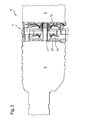
- FIG. 3 shows that the intake module 7 has the already mentioned suction fan wheel 14, which is located in the region of a housing flange which forms a cooling flange 26 and is seated on the coupling shaft 27.
- the suction fan 14 is arranged on it. In operation, the suction air is guided past the housing flange 26 so that it is cooled. This results in a cooling of the gearbox and percussion, with these two modules are in the second functional part 6.
- either-as already explained-two fan wheels can be provided, one of which serves for cooling the motor (cooling fan wheel 13) and the other forms the suction fan wheel 14.
- a double blading that is, there is only one wheel provided, which carries on one side a first blading and on the other side a second blading.
- the first blading is used to cool the electric motor and the other blading forms the Sauglcommunerrad the suction module.
- FIG. 4 illustrates the representation of FIG. 3 in a perspective view.
- a suction opening 28 forming the air inlet opening 24 communicates with the suction fan wheel 14 via a suction channel 29 belonging to the air passage 22.
- a separating wall 30 between the suction fan 14 and the cooling fan 13 is also visible.
- a protective grid is assigned to prevent not attached to the electric hand tool machine deposition of suction of small material, resulting in damage to the Sauglproperrades 14 of the intake module. 7 could lead.
- This protective grid also prevents small parts from entering the suction module if the separating device is defective, for example a filter tear, or if a filter has been forgotten.
- the protective grid can be designed, in particular, as a ring grid, which runs around the motor shaft-at a distance therefrom-and prevents the penetration of particles and the like toward the suction fan wheel 14.
- both the first functional part 5 and the second functional part 6 are each arranged in a one-piece cup-shaped housing portion.
- the corresponding pot can - according to a particular embodiment - also extend beyond the suction module 7 and the suction module housing mitge.
- the motor part associated with the housing part may have said excess length to accommodate the suction module.
- the suction module 7 may alternatively be associated with a separate, separate housing portion which is designed substantially tubular.
Landscapes
- Engineering & Computer Science (AREA)
- Mechanical Engineering (AREA)
- Auxiliary Devices For Machine Tools (AREA)
- Percussive Tools And Related Accessories (AREA)
Applications Claiming Priority (1)
| Application Number | Priority Date | Filing Date | Title |
|---|---|---|---|
| DE102006029626A DE102006029626A1 (de) | 2006-06-28 | 2006-06-28 | Elektrohandwerkzeugmaschine mit Saugmodul für eine Staubabscheidevorrichtung |
Publications (3)
| Publication Number | Publication Date |
|---|---|
| EP1872916A2 true EP1872916A2 (fr) | 2008-01-02 |
| EP1872916A3 EP1872916A3 (fr) | 2010-03-24 |
| EP1872916B1 EP1872916B1 (fr) | 2011-12-21 |
Family
ID=38543990
Family Applications (1)
| Application Number | Title | Priority Date | Filing Date |
|---|---|---|---|
| EP07107536A Ceased EP1872916B1 (fr) | 2006-06-28 | 2007-05-04 | Machine-outil électromanuelle dotée d'un module d'aspiration pour un dispositif de coupe de la poussière |
Country Status (3)
| Country | Link |
|---|---|
| EP (1) | EP1872916B1 (fr) |
| CN (1) | CN101096098B (fr) |
| DE (1) | DE102006029626A1 (fr) |
Cited By (3)
| Publication number | Priority date | Publication date | Assignee | Title |
|---|---|---|---|---|
| CN109571123A (zh) * | 2017-09-28 | 2019-04-05 | 株式会社牧田 | 集尘装置 |
| JP2019063889A (ja) * | 2017-09-28 | 2019-04-25 | 株式会社マキタ | 作業工具 |
| WO2020106689A1 (fr) * | 2018-11-19 | 2020-05-28 | Milwaukee Electric Tool Corporation | Collecteur de poussière comprenant un mécanisme de nettoyage de filtre |
Families Citing this family (6)
| Publication number | Priority date | Publication date | Assignee | Title |
|---|---|---|---|---|
| DE102014210915A1 (de) * | 2014-06-06 | 2015-12-17 | Robert Bosch Gmbh | Elektrowerkzeugmaschine |
| CN106466833A (zh) * | 2015-08-14 | 2017-03-01 | 南京德朔实业有限公司 | 附件装置及其与动力工具的组合 |
| US11298788B2 (en) * | 2018-06-19 | 2022-04-12 | Makita Corporation | Electric power tool dust collection system |
| EP4126448B1 (fr) | 2020-03-25 | 2025-11-26 | Milwaukee Electric Tool Corporation | Ensemble collecteur de poussière |
| CN115570179A (zh) | 2021-07-06 | 2023-01-06 | 南京泉峰科技有限公司 | 电钻及电动工具 |
| JP7849603B2 (ja) * | 2022-08-10 | 2026-04-22 | 工機ホールディングス株式会社 | 作業機および作業機システム |
Family Cites Families (7)
| Publication number | Priority date | Publication date | Assignee | Title |
|---|---|---|---|---|
| DE4206383A1 (de) * | 1992-02-29 | 1993-09-02 | Bosch Gmbh Robert | Handwerkzeugmaschine |
| DE19603528B4 (de) * | 1996-02-01 | 2005-01-13 | Robert Bosch Gmbh | Handwerkzeugmaschine |
| DE19941620A1 (de) * | 1999-09-01 | 2001-03-08 | Bosch Gmbh Robert | Handwerkzeugmaschine |
| DE10112129A1 (de) * | 2001-03-14 | 2002-09-19 | Hilti Ag | Saugmodul |
| ITMI20030961A1 (it) * | 2003-05-14 | 2004-11-15 | Guido Valentini | Utensile motorizzato con capacita' di aspirazione e raccolta polvere. |
| DE10342507A1 (de) * | 2003-09-12 | 2005-04-14 | Hilti Ag | Absaugvorrichtung |
| DE10346207A1 (de) * | 2003-10-06 | 2005-04-28 | Bosch Gmbh Robert | Absaugvorrichtung für eine Werkzeugmaschine |
-
2006
- 2006-06-28 DE DE102006029626A patent/DE102006029626A1/de not_active Withdrawn
-
2007
- 2007-05-04 EP EP07107536A patent/EP1872916B1/fr not_active Ceased
- 2007-06-28 CN CN2007101270436A patent/CN101096098B/zh active Active
Cited By (5)
| Publication number | Priority date | Publication date | Assignee | Title |
|---|---|---|---|---|
| CN109571123A (zh) * | 2017-09-28 | 2019-04-05 | 株式会社牧田 | 集尘装置 |
| JP2019063889A (ja) * | 2017-09-28 | 2019-04-25 | 株式会社マキタ | 作業工具 |
| US11446780B2 (en) | 2017-09-28 | 2022-09-20 | Makita Corporation | Dust collector |
| WO2020106689A1 (fr) * | 2018-11-19 | 2020-05-28 | Milwaukee Electric Tool Corporation | Collecteur de poussière comprenant un mécanisme de nettoyage de filtre |
| US11673217B2 (en) | 2018-11-19 | 2023-06-13 | Milwaukee Electric Tool Corporation | Dust collector including filter cleaning mechanism |
Also Published As
| Publication number | Publication date |
|---|---|
| EP1872916B1 (fr) | 2011-12-21 |
| EP1872916A3 (fr) | 2010-03-24 |
| CN101096098A (zh) | 2008-01-02 |
| CN101096098B (zh) | 2013-02-13 |
| DE102006029626A1 (de) | 2008-01-03 |
Similar Documents
| Publication | Publication Date | Title |
|---|---|---|
| EP1872916B1 (fr) | Machine-outil électromanuelle dotée d'un module d'aspiration pour un dispositif de coupe de la poussière | |
| DE102004029220B4 (de) | Handwerkzeuggerät mit Staubabsaugmodul | |
| EP2156537B1 (fr) | Moteur électrique à prise moteur | |
| EP0579964B1 (fr) | Scie portative munie d'un dispositif d'aspiration | |
| DE102017201558A1 (de) | Zubehörvorrichtung für eine Handwerkzeugmaschine | |
| DE102010063515A1 (de) | Saugmodul und Handwerkzeugmaschine mit Saugmodul | |
| DE10305350A1 (de) | Handgeführtes Elektrowerkzeug | |
| DE102018123752A1 (de) | Staubsammler | |
| DE102016210853A1 (de) | Handwerkzeugmaschine mit einer Kühleinheit | |
| DE102007056381A1 (de) | Handwerkzeugmaschine | |
| DE202006002330U1 (de) | Absaugvorrichtung | |
| DE102017201565A1 (de) | Zubehörvorrichtung für eine Handwerkzeugmaschine | |
| EP0794038A2 (fr) | Outil à main avec un arrangement de refroidissement | |
| WO2017102127A1 (fr) | Couvercle de boîtier pour machine-outil portative | |
| DE202011001475U1 (de) | Elektrowerkzeugmaschine, insbesondere eine Schleif- oder Poliermaschine | |
| EP2104585A1 (fr) | Machine-outil à main avec une unité d'aspiration | |
| WO2007080003A1 (fr) | Machine-outil portative | |
| DE19603528B4 (de) | Handwerkzeugmaschine | |
| DE102017201567A1 (de) | Zubehörvorrichtung für eine Handwerkzeugmaschine | |
| DE112018000849T5 (de) | Luftvorreinigungsbaugruppe und Elektrowerkzeug mit einer derartigen Luftvorreinigungsbaugruppe | |
| DE19600339C1 (de) | Handwerkzeug | |
| EP1968772B1 (fr) | Outil electrique manuel | |
| DE102017201560A1 (de) | Zubehörvorrichtung für eine Handwerkzeugmaschine | |
| AT518218B1 (de) | Luftgekühlte elektrische Maschine | |
| DE102017201563A1 (de) | Zubehörvorrichtung für eine Handwerkzeugmaschine |
Legal Events
| Date | Code | Title | Description |
|---|---|---|---|
| PUAI | Public reference made under article 153(3) epc to a published international application that has entered the european phase |
Free format text: ORIGINAL CODE: 0009012 |
|
| AK | Designated contracting states |
Kind code of ref document: A2 Designated state(s): AT BE BG CH CY CZ DE DK EE ES FI FR GB GR HU IE IS IT LI LT LU LV MC MT NL PL PT RO SE SI SK TR |
|
| AX | Request for extension of the european patent |
Extension state: AL BA HR MK YU |
|
| PUAL | Search report despatched |
Free format text: ORIGINAL CODE: 0009013 |
|
| AK | Designated contracting states |
Kind code of ref document: A3 Designated state(s): AT BE BG CH CY CZ DE DK EE ES FI FR GB GR HU IE IS IT LI LT LU LV MC MT NL PL PT RO SE SI SK TR |
|
| AX | Request for extension of the european patent |
Extension state: AL BA HR MK RS |
|
| RIC1 | Information provided on ipc code assigned before grant |
Ipc: B25F 5/00 20060101AFI20071012BHEP Ipc: B23Q 11/00 20060101ALI20100212BHEP Ipc: B25D 16/00 20060101ALI20100212BHEP |
|
| 17P | Request for examination filed |
Effective date: 20100924 |
|
| AKX | Designation fees paid |
Designated state(s): DE FR GB |
|
| 17Q | First examination report despatched |
Effective date: 20101213 |
|
| RIC1 | Information provided on ipc code assigned before grant |
Ipc: B25D 16/00 20060101ALI20110726BHEP Ipc: B23Q 11/00 20060101ALI20110726BHEP Ipc: B25F 5/00 20060101AFI20110726BHEP |
|
| GRAP | Despatch of communication of intention to grant a patent |
Free format text: ORIGINAL CODE: EPIDOSNIGR1 |
|
| GRAS | Grant fee paid |
Free format text: ORIGINAL CODE: EPIDOSNIGR3 |
|
| GRAA | (expected) grant |
Free format text: ORIGINAL CODE: 0009210 |
|
| AK | Designated contracting states |
Kind code of ref document: B1 Designated state(s): DE FR GB |
|
| REG | Reference to a national code |
Ref country code: GB Ref legal event code: FG4D Free format text: NOT ENGLISH |
|
| REG | Reference to a national code |
Ref country code: DE Ref legal event code: R096 Ref document number: 502007008892 Country of ref document: DE Effective date: 20120223 |
|
| PLBE | No opposition filed within time limit |
Free format text: ORIGINAL CODE: 0009261 |
|
| STAA | Information on the status of an ep patent application or granted ep patent |
Free format text: STATUS: NO OPPOSITION FILED WITHIN TIME LIMIT |
|
| 26N | No opposition filed |
Effective date: 20120924 |
|
| REG | Reference to a national code |
Ref country code: DE Ref legal event code: R097 Ref document number: 502007008892 Country of ref document: DE Effective date: 20120924 |
|
| REG | Reference to a national code |
Ref country code: FR Ref legal event code: PLFP Year of fee payment: 10 |
|
| REG | Reference to a national code |
Ref country code: FR Ref legal event code: PLFP Year of fee payment: 11 |
|
| REG | Reference to a national code |
Ref country code: FR Ref legal event code: PLFP Year of fee payment: 12 |
|
| PGFP | Annual fee paid to national office [announced via postgrant information from national office to epo] |
Ref country code: FR Payment date: 20230517 Year of fee payment: 17 |
|
| PGFP | Annual fee paid to national office [announced via postgrant information from national office to epo] |
Ref country code: GB Payment date: 20230522 Year of fee payment: 17 |
|
| PGFP | Annual fee paid to national office [announced via postgrant information from national office to epo] |
Ref country code: DE Payment date: 20240726 Year of fee payment: 18 |
|
| GBPC | Gb: european patent ceased through non-payment of renewal fee |
Effective date: 20240504 |
|
| PG25 | Lapsed in a contracting state [announced via postgrant information from national office to epo] |
Ref country code: FR Free format text: LAPSE BECAUSE OF NON-PAYMENT OF DUE FEES Effective date: 20240531 |
|
| PG25 | Lapsed in a contracting state [announced via postgrant information from national office to epo] |
Ref country code: GB Free format text: LAPSE BECAUSE OF NON-PAYMENT OF DUE FEES Effective date: 20240504 |
|
| REG | Reference to a national code |
Ref country code: DE Ref legal event code: R119 Ref document number: 502007008892 Country of ref document: DE |
|
| PG25 | Lapsed in a contracting state [announced via postgrant information from national office to epo] |
Ref country code: DE Free format text: LAPSE BECAUSE OF NON-PAYMENT OF DUE FEES Effective date: 20251202 |