EP1872971A1 - Fahrradnabe mit verkürzter Distanz zur Leerlaufdrehung - Google Patents
Fahrradnabe mit verkürzter Distanz zur Leerlaufdrehung Download PDFInfo
- Publication number
- EP1872971A1 EP1872971A1 EP06013206A EP06013206A EP1872971A1 EP 1872971 A1 EP1872971 A1 EP 1872971A1 EP 06013206 A EP06013206 A EP 06013206A EP 06013206 A EP06013206 A EP 06013206A EP 1872971 A1 EP1872971 A1 EP 1872971A1
- Authority
- EP
- European Patent Office
- Prior art keywords
- mounting portion
- pawl member
- hub
- locking
- locking ring
- Prior art date
- Legal status (The legal status is an assumption and is not a legal conclusion. Google has not performed a legal analysis and makes no representation as to the accuracy of the status listed.)
- Granted
Links
Images




Classifications
-
- F—MECHANICAL ENGINEERING; LIGHTING; HEATING; WEAPONS; BLASTING
- F16—ENGINEERING ELEMENTS AND UNITS; GENERAL MEASURES FOR PRODUCING AND MAINTAINING EFFECTIVE FUNCTIONING OF MACHINES OR INSTALLATIONS; THERMAL INSULATION IN GENERAL
- F16D—COUPLINGS FOR TRANSMITTING ROTATION; CLUTCHES; BRAKES
- F16D41/00—Freewheels or freewheel clutches
- F16D41/24—Freewheels or freewheel clutches specially adapted for cycles
- F16D41/32—Freewheels or freewheel clutches specially adapted for cycles with non-hinged detent
Definitions
- the present invention relates to a hub and, more particularly, to a hub for a bicycle.
- a conventional ratchet hub for a bicycle in accordance with the prior art shown in Figs. 10 and 11 comprises a shaft 71, a hub body 70 rotatably mounted on the shaft 71 and having an inside formed with a fixing recess 72, a locking ring 73 secured in the fixing recess 72 of the hub body 70 to drive and rotate hub body 70 and having an inside formed with a plurality of oneway ratchet teeth 74, a drive seat 80 rotatably mounted on the shaft 71 and having an end face 81 extended into the locking ring 73 and formed with a plurality of receiving slots 82, a plurality of pawl members 83 each pivotally mounted in the respective receiving slot 82 of the drive seat 80 and each meshing with the oneway ratchet teeth 74 of the locking ring 73, and an elastic ring 85 enclosed around the pawl members 83 to pivot the pawl members 83 outwardly in an inclined manner so that the pawl members 83 are engaged with the oneway ratchet
- the hub body 70 is connected to a wheel of the bicycle.
- the shaft 71 is connected to a frame of the bicycle.
- the drive seat 80 is connected to a freewheel of the bicycle.
- the freewheel of the bicycle is driven by a chain which is driven by a chainwheel which is driven by a pedal that is pedalled by a rider.
- the drive seat 80 performs an idle rotation, so that the locking ring 73 and the hub body 70 are not rotated by the drive seat 80 and will not interfere with rotation of the drive seat 80.
- the rotation speed of the drive seat 80 or the flywheel
- the locking ring 73 and the hub body 70 are rotated by the drive seat 80 again.
- each of the pawl members 83 is pivotally mounted in the respective receiving slot 82 of the drive seat 80 and is engaged with the oneway ratchet teeth 74 of the locking ring 73 in an oblique manner, so that the length of each of the pawl members 83 is increased, and the tooth distance of the oneway ratchet teeth 74 of the locking ring 73 is also increased to mate with each of the pawl members 83, thereby lengthening the idle rotation distance "T1" (which is defined by the tooth distance of the oneway ratchet teeth 74 of the locking ring 73) between the locking ring 73 and each of the pawl members 83.
- T1 which is defined by the tooth distance of the oneway ratchet teeth 74 of the locking ring 73
- the primary objective of the present invention is to provide a bicycle hub having a shorter idle rotation distance.
- Another objective of the present invention is to provide a hub, wherein the idle rotation distance between the locking ring and the pawl member is shortened.
- a preferred embodiment of a hub is provided with locking teeth of a pawl member and locking teeth of a locking ring being arranged successively, so that the locking ring engages the pawl member immediately after the idle rotation of the drive seat, thereby shortening the idle rotation distance between the locking ring and the pawl member.
- the hub has a shorter idle rotation distance, so that the hub body is driven by the drive seat immediately after the idle rotation of the drive seat, thereby facilitating the rider pedaling the bicycle.
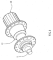
- Fig. 1 is a perspective view of a hub in accordance with the preferred 20 embodiment of the present invention.
- Fig. 2 is an exploded perspective view of the hub as shown in Fig. 1.
- Fig. 3 is a perspective view of a pawl member of the hub as shown in Fig. 2.
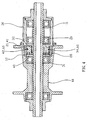
- Fig. 4 is a plan cross-sectional view of the hub as shown in Fig. 1.
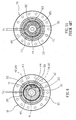
- Fig. 5 is a schematic plan cross-sectional view of the hub as shown in Fig. 1.
- Fig. 6 is a plan cross-sectional view of the hub as shown in Fig. 1.
- Fig. 7 is a schematic plan cross-sectional view of a hub in accordance with another preferred embodiment of the present invention.
- Fig. 1 is a perspective view of a hub in accordance with the preferred 20 embodiment of the present invention.
- Fig. 2 is an exploded perspective view of the hub as shown in Fig. 1.
- Fig. 3 is a perspective view of a pawl member of the
- FIG. 8 is an exploded perspective view of a hub in accordance with another preferred embodiment of the present invention.
- Fig. 9 is a plan cross-sectional assembly view of the hub as shown in Fig. 8.
- Fig. 10 is an exploded perspective view of a conventional hub in accordance with the prior art.
- Fig. 11 is a plan cross-sectional assembly view of the conventional hub as shown in Fig. 10.
- a hub for a bicycle in accordance with the preferred embodiment of the present invention comprises a shaft 11, a hub body 10 rotatably mounted on the shaft 11, a drive seat 30 rotatably mounted on the shaft 11, a locking ring 20 mounted in either one of the hub body 10 and the drive seat 30 and having an inside formed with a plurality of locking teeth 21, a mounting portion 31 mounted on the other one of the hub body 10 and the drive seat 30 and extended into the locking ring 20, at least one pawl member 40 having a plurality of locking teeth 41 and movable on the mounting portion 31 between a first position where the locking teeth 41 of the pawl member 40 engage the locking teeth 21 of the locking ring 20 and a second position where the locking teeth 41 of the pawl member 40 disengage the locking teeth 21 of the locking ring 20, at least one elastic member 50 biased between the mounting portion 31 and the pawl member 40 to push the locking teeth 41 of the pawl member 40 toward the locking teeth 21 of the locking ring 20, and
- the locking ring 20 is mounted in the hub body 10 to drive and rotate the hub body 10, and the mounting portion 31 is mounted on the drive seat 30.
- the hub body 10 has an inside formed with a fixing recess 12, and the locking ring 20 is secured in the fixing recess 12 of the hub body 10 to drive and rotate the hub body 10.
- the mounting portion 31 has a periphery formed with a chamfered slideway 32, and the pawl member 40 is slidable in the slideway 32 of the mounting portion 31.
- the mounting portion 31 has a receiving space 44 defined between the pawl member 40 and a closed end of the slideway 32 of the mounting portion 31 to allow retracting movement of the pawl member 40.
- the closed end of the slideway 32 of the mounting portion 31 is formed with a limit recess 33 to receive a first end of the elastic member 50.
- the periphery of the mounting portion 31 is formed with a retaining groove 34 to retain the elastic ring 60.
- the pawl member 40 has a shape mating with that of the slideway 32 of the mounting portion 31 and has a size smaller than that of the slideway 32 of the mounting portion 3 1.
- the pawl member 40 has a periphery formed with the locking teeth 41.
- the periphery of the pawl member 40 is substantially arc-shaped and mates with the periphery of the mounting portion 31 to form a whole circle.
- the periphery of the pawl member 40 is formed with a retaining groove 42 to retain the elastic ring 60.
- the retaining groove 42 of the pawl member 40 and the retaining groove 34 of the mounting portion 31 form an annular groove.
- the pawl member 40 has a substantially sector-shaped profile and has a first side slidable in the slideway 32 of the mounting portion 31 and a second side formed with a limit recess 43 to receive a second end of the elastic member 50.
- the drive seat 30 is rotated relative to the hub body 10 in a second direction (in the counterclockwise direction) as shown in Fig. 6.
- the pawl member 40 is pressed inwardly relative to the mounting portion 31 to the second position to retract into the receiving space 44, and the locking teeth 41 of the pawl member 40 disengage the locking teeth 21 of the locking ring 20, so that the locking ring 20 is not rotated with the mounting portion 31, and the drive seat 30 and the hub body 10 perform an idle rotation.
- rotation of the locking ring 20 and the hub body 10 will not interfere with rotation of the mounting portion 31 and the drive seat 30.
- the locking teeth 41 of the pawl member 40 and the locking teeth 21 of the locking ring 20 are arranged successively, so that the locking ring 20 engages the pawl member 40 immediately after the idle rotation of the drive seat 30, thereby shortening the idle rotation distance "T2" (which is defined by the tooth distance of the locking teeth 21 of the locking ring 20) between the locking ring 20 and the pawl member 40, such that the hub body 10 is driven by the drive seat 30 immediately after the idle rotation of the drive seat 30, thereby facilitating the rider pedaling the bicycle.
- T2 which is defined by the tooth distance of the locking teeth 21 of the locking ring 20
- the mounting portion 31 has an oblique gap 45 defined between contact sides of the pawl member 40 and the slideway 32 of the mounting portion 31 and connected to the receiving space 44 to allow retracting movement of the pawl member 40.
- the pawl member 40 is pressed inwardly relative to the mounting portion 31 to the second position, the pawl member 40 is retracted into the receiving space 44 and the oblique gap 45, and when the pawl member 40 is pushed outwardly relative to the mounting portion 31 to the first position, the pawl member 40 is swayed outwardly, so that the locking teeth 41 of the pawl member 40 engage the locking teeth 21 of the locking ring 20 closely.
- the locking ring 20 is mounted in the drive seat 30, and the mounting portion 31 is mounted on the hub body 10 to drive and rotate the hub body 10.
- the locking teeth 41 of the pawl member 40 and the locking teeth 21 of the locking ring 20 are arranged successively, so that the locking ring 20 engages the pawl member 40 immediately after the idle rotation of the drive seat 30, thereby shortening the idle rotation distance "T2" between the locking ring 20 and the pawl member 40.
- the hub has a shorter idle rotation distance, so that the hub body 10 is driven by the drive seat 30 immediately after the idle rotation of the drive seat 30, thereby facilitating the rider pedaling the bicycle.
Landscapes
- Engineering & Computer Science (AREA)
- General Engineering & Computer Science (AREA)
- Mechanical Engineering (AREA)
- Axle Suspensions And Sidecars For Cycles (AREA)
- Transmission Devices (AREA)
Priority Applications (3)
| Application Number | Priority Date | Filing Date | Title |
|---|---|---|---|
| EP06013206A EP1872971B1 (de) | 2006-06-27 | 2006-06-27 | Fahrradnabe mit verkürzter Distanz zur Leerlaufdrehung |
| DE602006002977T DE602006002977D1 (de) | 2006-06-27 | 2006-06-27 | Fahrradnabe mit verkürzter Distanz zur Leerlaufdrehung |
| AT06013206T ATE409602T1 (de) | 2006-06-27 | 2006-06-27 | Fahrradnabe mit verkürzter distanz zur leerlaufdrehung |
Applications Claiming Priority (1)
| Application Number | Priority Date | Filing Date | Title |
|---|---|---|---|
| EP06013206A EP1872971B1 (de) | 2006-06-27 | 2006-06-27 | Fahrradnabe mit verkürzter Distanz zur Leerlaufdrehung |
Publications (2)
| Publication Number | Publication Date |
|---|---|
| EP1872971A1 true EP1872971A1 (de) | 2008-01-02 |
| EP1872971B1 EP1872971B1 (de) | 2008-10-01 |
Family
ID=37433731
Family Applications (1)
| Application Number | Title | Priority Date | Filing Date |
|---|---|---|---|
| EP06013206A Not-in-force EP1872971B1 (de) | 2006-06-27 | 2006-06-27 | Fahrradnabe mit verkürzter Distanz zur Leerlaufdrehung |
Country Status (3)
| Country | Link |
|---|---|
| EP (1) | EP1872971B1 (de) |
| AT (1) | ATE409602T1 (de) |
| DE (1) | DE602006002977D1 (de) |
Cited By (2)
| Publication number | Priority date | Publication date | Assignee | Title |
|---|---|---|---|---|
| CN102049967B (zh) * | 2009-11-06 | 2012-08-08 | 乔绅股份有限公司 | 常闭式自行车后花毂结构 |
| US11090977B2 (en) | 2018-07-06 | 2021-08-17 | Hayes Bicycle Group Inc. | Wheel hub assembly |
Citations (3)
| Publication number | Priority date | Publication date | Assignee | Title |
|---|---|---|---|---|
| US5704859A (en) * | 1996-10-16 | 1998-01-06 | National Science Council Of Republic Of China | Type of the compact freewheel body for bicycles |
| DE10012466A1 (de) * | 1999-03-22 | 2000-09-28 | William B Shook | Fahrradfreilaufmechanismus |
| US20050183918A1 (en) * | 2004-02-25 | 2005-08-25 | Hou Tien W. | Ratchet paw module structure |
-
2006
- 2006-06-27 EP EP06013206A patent/EP1872971B1/de not_active Not-in-force
- 2006-06-27 DE DE602006002977T patent/DE602006002977D1/de active Active
- 2006-06-27 AT AT06013206T patent/ATE409602T1/de not_active IP Right Cessation
Patent Citations (3)
| Publication number | Priority date | Publication date | Assignee | Title |
|---|---|---|---|---|
| US5704859A (en) * | 1996-10-16 | 1998-01-06 | National Science Council Of Republic Of China | Type of the compact freewheel body for bicycles |
| DE10012466A1 (de) * | 1999-03-22 | 2000-09-28 | William B Shook | Fahrradfreilaufmechanismus |
| US20050183918A1 (en) * | 2004-02-25 | 2005-08-25 | Hou Tien W. | Ratchet paw module structure |
Cited By (2)
| Publication number | Priority date | Publication date | Assignee | Title |
|---|---|---|---|---|
| CN102049967B (zh) * | 2009-11-06 | 2012-08-08 | 乔绅股份有限公司 | 常闭式自行车后花毂结构 |
| US11090977B2 (en) | 2018-07-06 | 2021-08-17 | Hayes Bicycle Group Inc. | Wheel hub assembly |
Also Published As
| Publication number | Publication date |
|---|---|
| EP1872971B1 (de) | 2008-10-01 |
| DE602006002977D1 (de) | 2008-11-13 |
| ATE409602T1 (de) | 2008-10-15 |
Similar Documents
| Publication | Publication Date | Title |
|---|---|---|
| US9669656B2 (en) | Bicycle freewheel | |
| US8276731B2 (en) | Normally closed soundless bicycle hub | |
| US7938242B2 (en) | Bicycle hub that will not drive the pedal and will not produce noise when the hub is rotated in the backward direction | |
| US8312976B2 (en) | High efficiency bicycle hub | |
| JPH09210101A (ja) | 自転車用フリーホイールの爪音消し機構 | |
| US8556055B2 (en) | Driving apparatus for rear hub of bicycle | |
| CN101287923B (zh) | 超越离合器 | |
| US6502679B1 (en) | Low-noise low-friction resistance, one-way drive car wheel assembly | |
| EP1872971B1 (de) | Fahrradnabe mit verkürzter Distanz zur Leerlaufdrehung | |
| KR20180127233A (ko) | 자전거용 다단기어 변속모터 | |
| CN114055996A (zh) | 一种单向传动花鼓结构以及自行车 | |
| EP3263949A1 (de) | Getriebevorrichtung mit anpassbarer drehzahl | |
| US7445296B1 (en) | Bicycle hub having enhanced strength | |
| EP2204291B1 (de) | Fahrradnabe, die das Pedal nicht bewegt und keine Geräusche erzeugt, wenn sich die Nabe beim Rückwärtstreten dreht | |
| US6308811B1 (en) | Method of side transmission through unidirectional clutch and the clutch for such purpose | |
| GB2128273A (en) | A pawl and ratchet driving assembly particularly for freewheel bicycle hubs | |
| EP2770224A1 (de) | Antriebssystem für eine Fahrradnabe | |
| US20050183918A1 (en) | Ratchet paw module structure | |
| CA3207911C (en) | A mechanical assembly to disengage a bicycle rear hub with a pawl and ratchet-ring clutch mechanism | |
| FR3152299A1 (fr) | Transmission du type à cardan pour véhicule | |
| US20250033408A1 (en) | Mechanical assembly to disengage a bicycle rear hub with a pawl and ratchet-ring clutch mechanism | |
| FR2776729A1 (fr) | Roue libre de bicyclette a cliquet auto-engageant | |
| TWI291420B (en) | Hub ratchet device capable of enhancing damping force during skipping | |
| KR100941455B1 (ko) | 속도변환장치의 브레이크장치 | |
| US20220332143A1 (en) | Freehub of bicycle |
Legal Events
| Date | Code | Title | Description |
|---|---|---|---|
| PUAI | Public reference made under article 153(3) epc to a published international application that has entered the european phase |
Free format text: ORIGINAL CODE: 0009012 |
|
| 17P | Request for examination filed |
Effective date: 20060707 |
|
| AK | Designated contracting states |
Kind code of ref document: A1 Designated state(s): AT BE BG CH CY CZ DE DK EE ES FI FR GB GR HU IE IS IT LI LT LU LV MC NL PL PT RO SE SI SK TR |
|
| AX | Request for extension of the european patent |
Extension state: AL BA HR MK YU |
|
| GRAP | Despatch of communication of intention to grant a patent |
Free format text: ORIGINAL CODE: EPIDOSNIGR1 |
|
| GRAS | Grant fee paid |
Free format text: ORIGINAL CODE: EPIDOSNIGR3 |
|
| GRAA | (expected) grant |
Free format text: ORIGINAL CODE: 0009210 |
|
| AKX | Designation fees paid |
Designated state(s): AT BE BG CH CY CZ DE DK EE ES FI FR GB GR HU IE IS IT LI LT LU LV MC NL PL PT RO SE SI SK TR |
|
| AK | Designated contracting states |
Kind code of ref document: B1 Designated state(s): AT BE BG CH CY CZ DE DK EE ES FI FR GB GR HU IE IS IT LI LT LU LV MC NL PL PT RO SE SI SK TR |
|
| REG | Reference to a national code |
Ref country code: GB Ref legal event code: FG4D |
|
| REG | Reference to a national code |
Ref country code: CH Ref legal event code: EP |
|
| REG | Reference to a national code |
Ref country code: CH Ref legal event code: NV Representative=s name: E. BLUM & CO. AG PATENT- UND MARKENANWAELTE VSP |
|
| REG | Reference to a national code |
Ref country code: IE Ref legal event code: FG4D |
|
| REF | Corresponds to: |
Ref document number: 602006002977 Country of ref document: DE Date of ref document: 20081113 Kind code of ref document: P |
|
| PG25 | Lapsed in a contracting state [announced via postgrant information from national office to epo] |
Ref country code: SI Free format text: LAPSE BECAUSE OF FAILURE TO SUBMIT A TRANSLATION OF THE DESCRIPTION OR TO PAY THE FEE WITHIN THE PRESCRIBED TIME-LIMIT Effective date: 20081001 |
|
| NLV1 | Nl: lapsed or annulled due to failure to fulfill the requirements of art. 29p and 29m of the patents act | ||
| PG25 | Lapsed in a contracting state [announced via postgrant information from national office to epo] |
Ref country code: ES Free format text: LAPSE BECAUSE OF FAILURE TO SUBMIT A TRANSLATION OF THE DESCRIPTION OR TO PAY THE FEE WITHIN THE PRESCRIBED TIME-LIMIT Effective date: 20090112 Ref country code: BG Free format text: LAPSE BECAUSE OF FAILURE TO SUBMIT A TRANSLATION OF THE DESCRIPTION OR TO PAY THE FEE WITHIN THE PRESCRIBED TIME-LIMIT Effective date: 20090101 Ref country code: AT Free format text: LAPSE BECAUSE OF FAILURE TO SUBMIT A TRANSLATION OF THE DESCRIPTION OR TO PAY THE FEE WITHIN THE PRESCRIBED TIME-LIMIT Effective date: 20081001 Ref country code: LT Free format text: LAPSE BECAUSE OF FAILURE TO SUBMIT A TRANSLATION OF THE DESCRIPTION OR TO PAY THE FEE WITHIN THE PRESCRIBED TIME-LIMIT Effective date: 20081001 |
|
| PG25 | Lapsed in a contracting state [announced via postgrant information from national office to epo] |
Ref country code: FI Free format text: LAPSE BECAUSE OF FAILURE TO SUBMIT A TRANSLATION OF THE DESCRIPTION OR TO PAY THE FEE WITHIN THE PRESCRIBED TIME-LIMIT Effective date: 20081001 Ref country code: IS Free format text: LAPSE BECAUSE OF FAILURE TO SUBMIT A TRANSLATION OF THE DESCRIPTION OR TO PAY THE FEE WITHIN THE PRESCRIBED TIME-LIMIT Effective date: 20090201 Ref country code: LV Free format text: LAPSE BECAUSE OF FAILURE TO SUBMIT A TRANSLATION OF THE DESCRIPTION OR TO PAY THE FEE WITHIN THE PRESCRIBED TIME-LIMIT Effective date: 20081001 Ref country code: NL Free format text: LAPSE BECAUSE OF FAILURE TO SUBMIT A TRANSLATION OF THE DESCRIPTION OR TO PAY THE FEE WITHIN THE PRESCRIBED TIME-LIMIT Effective date: 20081001 Ref country code: PT Free format text: LAPSE BECAUSE OF FAILURE TO SUBMIT A TRANSLATION OF THE DESCRIPTION OR TO PAY THE FEE WITHIN THE PRESCRIBED TIME-LIMIT Effective date: 20090302 Ref country code: PL Free format text: LAPSE BECAUSE OF FAILURE TO SUBMIT A TRANSLATION OF THE DESCRIPTION OR TO PAY THE FEE WITHIN THE PRESCRIBED TIME-LIMIT Effective date: 20081001 |
|
| PG25 | Lapsed in a contracting state [announced via postgrant information from national office to epo] |
Ref country code: DK Free format text: LAPSE BECAUSE OF FAILURE TO SUBMIT A TRANSLATION OF THE DESCRIPTION OR TO PAY THE FEE WITHIN THE PRESCRIBED TIME-LIMIT Effective date: 20081001 Ref country code: EE Free format text: LAPSE BECAUSE OF FAILURE TO SUBMIT A TRANSLATION OF THE DESCRIPTION OR TO PAY THE FEE WITHIN THE PRESCRIBED TIME-LIMIT Effective date: 20081001 Ref country code: RO Free format text: LAPSE BECAUSE OF FAILURE TO SUBMIT A TRANSLATION OF THE DESCRIPTION OR TO PAY THE FEE WITHIN THE PRESCRIBED TIME-LIMIT Effective date: 20081001 Ref country code: BE Free format text: LAPSE BECAUSE OF FAILURE TO SUBMIT A TRANSLATION OF THE DESCRIPTION OR TO PAY THE FEE WITHIN THE PRESCRIBED TIME-LIMIT Effective date: 20081001 |
|
| PLBE | No opposition filed within time limit |
Free format text: ORIGINAL CODE: 0009261 |
|
| STAA | Information on the status of an ep patent application or granted ep patent |
Free format text: STATUS: NO OPPOSITION FILED WITHIN TIME LIMIT |
|
| PG25 | Lapsed in a contracting state [announced via postgrant information from national office to epo] |
Ref country code: CZ Free format text: LAPSE BECAUSE OF FAILURE TO SUBMIT A TRANSLATION OF THE DESCRIPTION OR TO PAY THE FEE WITHIN THE PRESCRIBED TIME-LIMIT Effective date: 20081001 Ref country code: SE Free format text: LAPSE BECAUSE OF FAILURE TO SUBMIT A TRANSLATION OF THE DESCRIPTION OR TO PAY THE FEE WITHIN THE PRESCRIBED TIME-LIMIT Effective date: 20090101 |
|
| 26N | No opposition filed |
Effective date: 20090702 |
|
| PG25 | Lapsed in a contracting state [announced via postgrant information from national office to epo] |
Ref country code: SK Free format text: LAPSE BECAUSE OF FAILURE TO SUBMIT A TRANSLATION OF THE DESCRIPTION OR TO PAY THE FEE WITHIN THE PRESCRIBED TIME-LIMIT Effective date: 20081001 |
|
| PG25 | Lapsed in a contracting state [announced via postgrant information from national office to epo] |
Ref country code: MC Free format text: LAPSE BECAUSE OF NON-PAYMENT OF DUE FEES Effective date: 20090630 |
|
| REG | Reference to a national code |
Ref country code: IE Ref legal event code: MM4A |
|
| PG25 | Lapsed in a contracting state [announced via postgrant information from national office to epo] |
Ref country code: IE Free format text: LAPSE BECAUSE OF NON-PAYMENT OF DUE FEES Effective date: 20090627 |
|
| PG25 | Lapsed in a contracting state [announced via postgrant information from national office to epo] |
Ref country code: GR Free format text: LAPSE BECAUSE OF FAILURE TO SUBMIT A TRANSLATION OF THE DESCRIPTION OR TO PAY THE FEE WITHIN THE PRESCRIBED TIME-LIMIT Effective date: 20090102 |
|
| PG25 | Lapsed in a contracting state [announced via postgrant information from national office to epo] |
Ref country code: LU Free format text: LAPSE BECAUSE OF NON-PAYMENT OF DUE FEES Effective date: 20090627 |
|
| PG25 | Lapsed in a contracting state [announced via postgrant information from national office to epo] |
Ref country code: HU Free format text: LAPSE BECAUSE OF FAILURE TO SUBMIT A TRANSLATION OF THE DESCRIPTION OR TO PAY THE FEE WITHIN THE PRESCRIBED TIME-LIMIT Effective date: 20090402 |
|
| PG25 | Lapsed in a contracting state [announced via postgrant information from national office to epo] |
Ref country code: TR Free format text: LAPSE BECAUSE OF FAILURE TO SUBMIT A TRANSLATION OF THE DESCRIPTION OR TO PAY THE FEE WITHIN THE PRESCRIBED TIME-LIMIT Effective date: 20081001 |
|
| PG25 | Lapsed in a contracting state [announced via postgrant information from national office to epo] |
Ref country code: CY Free format text: LAPSE BECAUSE OF FAILURE TO SUBMIT A TRANSLATION OF THE DESCRIPTION OR TO PAY THE FEE WITHIN THE PRESCRIBED TIME-LIMIT Effective date: 20081001 |
|
| REG | Reference to a national code |
Ref country code: FR Ref legal event code: PLFP Year of fee payment: 10 |
|
| REG | Reference to a national code |
Ref country code: DE Ref legal event code: R082 Ref document number: 602006002977 Country of ref document: DE Representative=s name: CABINET CHAILLOT, FR |
|
| PGFP | Annual fee paid to national office [announced via postgrant information from national office to epo] |
Ref country code: FR Payment date: 20150617 Year of fee payment: 10 Ref country code: IT Payment date: 20150615 Year of fee payment: 10 |
|
| PGFP | Annual fee paid to national office [announced via postgrant information from national office to epo] |
Ref country code: DE Payment date: 20150716 Year of fee payment: 10 Ref country code: CH Payment date: 20150716 Year of fee payment: 10 Ref country code: GB Payment date: 20150706 Year of fee payment: 10 |
|
| REG | Reference to a national code |
Ref country code: DE Ref legal event code: R119 Ref document number: 602006002977 Country of ref document: DE |
|
| REG | Reference to a national code |
Ref country code: CH Ref legal event code: PL |
|
| GBPC | Gb: european patent ceased through non-payment of renewal fee |
Effective date: 20160627 |
|
| REG | Reference to a national code |
Ref country code: FR Ref legal event code: ST Effective date: 20170228 |
|
| PG25 | Lapsed in a contracting state [announced via postgrant information from national office to epo] |
Ref country code: LI Free format text: LAPSE BECAUSE OF NON-PAYMENT OF DUE FEES Effective date: 20160630 Ref country code: DE Free format text: LAPSE BECAUSE OF NON-PAYMENT OF DUE FEES Effective date: 20170103 Ref country code: CH Free format text: LAPSE BECAUSE OF NON-PAYMENT OF DUE FEES Effective date: 20160630 Ref country code: FR Free format text: LAPSE BECAUSE OF NON-PAYMENT OF DUE FEES Effective date: 20160630 |
|
| PG25 | Lapsed in a contracting state [announced via postgrant information from national office to epo] |
Ref country code: GB Free format text: LAPSE BECAUSE OF NON-PAYMENT OF DUE FEES Effective date: 20160627 |
|
| PG25 | Lapsed in a contracting state [announced via postgrant information from national office to epo] |
Ref country code: IT Free format text: LAPSE BECAUSE OF NON-PAYMENT OF DUE FEES Effective date: 20160627 |