EP1873021A2 - Stossabsorbierende Struktur für Fahrzeug - Google Patents
Stossabsorbierende Struktur für Fahrzeug Download PDFInfo
- Publication number
- EP1873021A2 EP1873021A2 EP07251141A EP07251141A EP1873021A2 EP 1873021 A2 EP1873021 A2 EP 1873021A2 EP 07251141 A EP07251141 A EP 07251141A EP 07251141 A EP07251141 A EP 07251141A EP 1873021 A2 EP1873021 A2 EP 1873021A2
- Authority
- EP
- European Patent Office
- Prior art keywords
- shock absorbing
- spacer member
- shock
- vehicle
- connecting body
- Prior art date
- Legal status (The legal status is an assumption and is not a legal conclusion. Google has not performed a legal analysis and makes no representation as to the accuracy of the status listed.)
- Granted
Links
Images

Classifications
-
- B—PERFORMING OPERATIONS; TRANSPORTING
- B60—VEHICLES IN GENERAL
- B60R—VEHICLES, VEHICLE FITTINGS, OR VEHICLE PARTS, NOT OTHERWISE PROVIDED FOR
- B60R21/00—Arrangements or fittings on vehicles for protecting or preventing injuries to occupants or pedestrians in case of accidents or other traffic risks
- B60R21/02—Occupant safety arrangements or fittings, e.g. crash pads
- B60R21/04—Padded linings for the vehicle interior ; Energy absorbing structures associated with padded or non-padded linings
-
- B—PERFORMING OPERATIONS; TRANSPORTING
- B60—VEHICLES IN GENERAL
- B60R—VEHICLES, VEHICLE FITTINGS, OR VEHICLE PARTS, NOT OTHERWISE PROVIDED FOR
- B60R21/00—Arrangements or fittings on vehicles for protecting or preventing injuries to occupants or pedestrians in case of accidents or other traffic risks
- B60R21/02—Occupant safety arrangements or fittings, e.g. crash pads
- B60R21/04—Padded linings for the vehicle interior ; Energy absorbing structures associated with padded or non-padded linings
- B60R2021/0414—Padded linings for the vehicle interior ; Energy absorbing structures associated with padded or non-padded linings using energy absorbing ribs
-
- B—PERFORMING OPERATIONS; TRANSPORTING
- B60—VEHICLES IN GENERAL
- B60R—VEHICLES, VEHICLE FITTINGS, OR VEHICLE PARTS, NOT OTHERWISE PROVIDED FOR
- B60R21/00—Arrangements or fittings on vehicles for protecting or preventing injuries to occupants or pedestrians in case of accidents or other traffic risks
- B60R21/02—Occupant safety arrangements or fittings, e.g. crash pads
- B60R21/04—Padded linings for the vehicle interior ; Energy absorbing structures associated with padded or non-padded linings
- B60R2021/0435—Padded linings for the vehicle interior ; Energy absorbing structures associated with padded or non-padded linings associated with the side or roof pillars
-
- B—PERFORMING OPERATIONS; TRANSPORTING
- B60—VEHICLES IN GENERAL
- B60R—VEHICLES, VEHICLE FITTINGS, OR VEHICLE PARTS, NOT OTHERWISE PROVIDED FOR
- B60R21/00—Arrangements or fittings on vehicles for protecting or preventing injuries to occupants or pedestrians in case of accidents or other traffic risks
- B60R21/02—Occupant safety arrangements or fittings, e.g. crash pads
- B60R21/04—Padded linings for the vehicle interior ; Energy absorbing structures associated with padded or non-padded linings
- B60R2021/0442—Padded linings for the vehicle interior ; Energy absorbing structures associated with padded or non-padded linings associated with the roof panel
-
- B—PERFORMING OPERATIONS; TRANSPORTING
- B60—VEHICLES IN GENERAL
- B60R—VEHICLES, VEHICLE FITTINGS, OR VEHICLE PARTS, NOT OTHERWISE PROVIDED FOR
- B60R21/00—Arrangements or fittings on vehicles for protecting or preventing injuries to occupants or pedestrians in case of accidents or other traffic risks
- B60R21/02—Occupant safety arrangements or fittings, e.g. crash pads
- B60R21/04—Padded linings for the vehicle interior ; Energy absorbing structures associated with padded or non-padded linings
- B60R21/0428—Padded linings for the vehicle interior ; Energy absorbing structures associated with padded or non-padded linings associated with the side doors or panels, e.g. displaced towards the occupants in case of a side collision
-
- B—PERFORMING OPERATIONS; TRANSPORTING
- B60—VEHICLES IN GENERAL
- B60R—VEHICLES, VEHICLE FITTINGS, OR VEHICLE PARTS, NOT OTHERWISE PROVIDED FOR
- B60R21/00—Arrangements or fittings on vehicles for protecting or preventing injuries to occupants or pedestrians in case of accidents or other traffic risks
- B60R21/02—Occupant safety arrangements or fittings, e.g. crash pads
- B60R21/04—Padded linings for the vehicle interior ; Energy absorbing structures associated with padded or non-padded linings
- B60R21/045—Padded linings for the vehicle interior ; Energy absorbing structures associated with padded or non-padded linings associated with the instrument panel or dashboard
Definitions
- the present invention relates to a shock absorbing structure for a vehicle, and particularly to a shock absorbing structure for a vehicle capable of being advantageously arranged in an installation space between an interior components of the vehicle and a structural component of the vehicle body.
- a vehicle such as an automobile often has a shock absorbing structure fitted within an installation space between an interior component, such as a ceiling lining, a pillar garnish, a roof side rail, an instrument panel, a console box, etc., which has a high possibility of coming into contact with a vehicle occupant at a time of a collision accident, and a body structural component such as various panels constituting part of a body that are positioned at an opposite side (outer side) to the interior component side of a vehicle compartment, and in this way an impact imparted to the vehicle occupant is alleviated when the interior component contacts the vehicle occupant at the time of the collision accident, for thereby protecting the vehicle occupant.
- an interior component such as a ceiling lining, a pillar garnish, a roof side rail, an instrument panel, a console box, etc.
- the shape of the installation space for the shock absorbing structure between the interior component and the body structural component is generally different for each type of vehicle, which means that with this type of conventional shock absorbing structure the overall shape should match the shape of the respective installation space, and should be designed specifically for each type of vehicle.
- the shock absorbing structure is formed by die molding using a synthetic resin material, for example, there is caused a problem that the die is increased in size, and as a result of that the manufacturing cost of the die, and also the manufacturing cost of the shock absorbing structure, rise steeply.
- This shock absorbing structure for a vehicle has shock absorbing members that form a gap between the interior component and the body structural component, and are capable of being arranged in any of installation spaces that have different shapes from each other, and the shock absorbing structure has a spacer member, corresponding to at least a part of the gap formed between the interior component and the body structural component, attached to the shock absorbing members.
- shock absorbing structure In this type of shock absorbing structure, a single general purpose member is used as the shock absorbing member regardless of the shape of an installation space in which the shock absorbing structure is fitted is changed, and as a result, even if the type of vehicle into which the structure is to be fitted changes, a stable shock absorbing performance is ensured without any troublesome design changes relating to shock absorbing characteristics. Also, the gap formed inside the installation space between the interior component and the shock absorbing member can be advantageously eliminated or made as small as possible by using the spacer member, which means that various drawbacks due to the existence of this type of gap are effectively resolved.
- the spacer member is attached to the shock absorbing members via specified attachment parts. Therefore, in the case where each of the attachment parts for the spacer member provided on the shock absorbing member has an angular corner section and/or a thick-walled section, as described in JP-A-2004-189120 , for example, if the corner section is large, or the thick-walled section is extremely thick, rigidity of the shock absorbing member is excessive and the shock absorbing stroke will be reduced, and as a result there is an anxiety that attainment of sufficient shock absorbing performance will be difficult. Accordingly, the conventional shock absorbing structure for a vehicle leaves room for further improvement in this respect.
- the present invention has been made in light of the above described situation, and has as an object to provide an improved structure for a shock absorbing structure for a vehicle that is improved so as to exhibit a sufficient shock absorbing performance in a more stable manner while ensures an advantage of being formed in accordance with the shape of an installation space no matter what the shape of the installation space is.
- a principle of the present invention is to provide a shock absorbing structure for a vehicle to be installed in an installation space between a vehicle interior component and a body structural component of the vehicle, comprising: a plurality of shock absorbing members for absorbing an externally applied shock by being deformed by the application of the shock; and at least one connecting body each connecting adjacent ones of the shock absorbing members, characterized in that each of the at least one connecting body is provided with a spacer member which has a configuration corresponding to at least a part of that of a gap which is formed between each of the shock absorbing members and at least one of the vehicle interior component and the body structural component, when the plurality of shock absorbing members are installed in the installation space.
- the spacer member is located together with the shock absorbing member inside the installation space when the shock absorbing structure is installed inside the installation space. According to this arrangement, regardless of the shape of the installation space, either a gap is not formed at all between the interior component and the body structural component, or the gap is made as small as possible, and as a result various problems such as the generation of the abnormal noise and a loss of the feeling of high quality that attribute to the existence of this gap are advantageously eliminated.
- the shock absorbing structure for a vehicle it is possible to exhibit sufficient shock absorbing performance in a more stable manner regardless of the shape of the installation space, while maintaining the advantages obtained when the shock absorbing structure is formed in the shape corresponding to the shape of the installation space.
- the present invention is preferably practiced in at least the following features.
- a shock absorbing structure for a vehicle to be installed in an installation space between a vehicle interior component and a body structural component of the vehicle comprising:
- each of the plurality of shock absorbing members is formed of a main body which is made of a resin; and wherein the each of the plurality of shock absorbing members includes a tubular body (16) comprising side walls each of which extends in a direction in which the shock is applied and absorbs the shock by being deformed by the application of the shock.
- the impact load acts on the side wall of the cylindrical section of the main body which is made of resin constituting a shock absorbing members as a compressive load in the height direction, and the side wall is subjected to buckling deformation in the height direction.
- the shock is more efficiently and reliably absorbed by the shock absorbing member.
- shock absorbing structure for a vehicle according to any one of the above features (1) - (3), wherein the spacer member attached to the each of the at least one connecting body is formed of a plate member extending from the each of the at least one connecting body in a direction perpendicular to the direction in which the shock is externally applied; and wherein the spacer member comes into contact with the at least one of the vehicle interior component and the body structural component of the vehicle at an end portion of the spacer member, while the spacer member is installed in the installation space for the plurality of shock absorbing members.
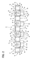
- Fig. 1 and Fig. 2 respectively schematically show a front appearance and upper surface appearance of a shock absorbing structure arranged in an installation space between a ceiling lining, being one type of vehicle interior component, and a roof panel, being one body structural component positioned opposing to the ceiling lining at an opposite side (rear side) to the vehicle compartment side, as one example of the shock absorbing structure for a vehicle having the structure according to the present invention.
- a shock absorbing structure 10 of this embodiment is constructed having a plurality of shock absorbing members 12 and a plurality of connecting bodies 14 that connect the plurality of shock absorbing members 12 to one another.
- each of the plurality of shock absorbing members 12 is formed of a tubular body 16 presenting a substantially angular cylindrical shape and a substantially rectangular top wall 18.
- the tubular body 16 of the shock absorbing member 12 has four side walls 20 formed as thin-walled plates presenting a substantially trapezoidal shape with an upper side being a specified dimension shorter than the lower side, and the side walls are inclined so as to gradually become closer as the side walls are closer to the axial center of the tubular body 16, and jutting up so as to extend upwards.
- the top wall 18 is also formed of a thin flat plate having substantially the same thickness as each side wall 20 of the tubular body 16, and is constructed by being integrated with the upper side edge section of each side wall 20 at the four edges of the top wall 18.
- each of the shock absorbing members 12, as will be described later, in a state located within the installation space between a top portion of the ceiling lining and a roof panel arranged opposing to the top portion, is constructed as an integral component comprising the tubular body 16 having four side walls 20 erected so as to extend in the direction in which the shock is primarily applied (a shock-receiving direction or a direction in which the ceiling lining and the roof panel are opposed to each other) and the top wall 18 blocks an upper opening section of the tubular body 16 (see Fig. 4).
- each of the shock absorbing member 12 has an angular cylindrical shape with one end closed off having a rectangular cross sectional shape taken along a surface perpendicular to an axis of the shock absorbing member 12, and the cross sectional surface area becomes gradually smaller as the cross sectional area is closer to the tip end.
- Each of a plurality of these shock absorbing members 12 is independently arranged so as to be aligned in a row (in a straight line) with adjacent side walls 20 opposing to each other, keeping a specified distance apart from each other.
- each of the shock absorbing members 12 is formed of a synthetic resin material such as an olefin resin that is easily subjected to the buckling deformation, such as polypropylene, polyethylene, and polybutene. In this manner, the material that is easy to be subjected to the buckling deformation is used as the structural material of the shock absorbing member 12.
- a synthetic resin material such as an olefin resin that is easily subjected to the buckling deformation, such as polypropylene, polyethylene, and polybutene.
- the tubular body 16 of the shock absorbing member 12 is formed having an angular cylindrical shape that has a cross sectional surface area taken along the surface perpendicular to the axis that becomes smaller as the cross sectional surface area is closer to the tip, which means that when the shock is applied to the shock absorbing member 12 (the shock absorbing structure 10), the shock absorbing member 12 is easily deformed or buckled in the height or the axial direction of the shock absorbing member 12, while each side wall 20 of the tubular body 16 is prevented from being superposed on each other in the axial direction, as much as possible.
- the shock absorbing member 12 even in the event that the height of each side wall 20 of the tubular body 16 is made low, and the shock absorbing stroke is made small, the impact is efficiently absorbed to at least a previously determined (designed) extent, and sufficient shock absorbing performance is ensured. Also, the size of the shock absorbing stroke, that is, the height of the shock absorbing member 12 having the tubular body 16 is either substantially the same as or slightly smaller than a distance between the ceiling lining and the roof panel, described later, where the shock absorbing member 12 is installed (see to Fig. 4).
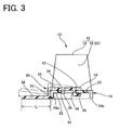
- each of these connecting bodies 14 comprises a rectangular flat plate section 22 having substantially the same width as the width of lower section of each side wall 20 of the shock absorbing member 12 and a specified length, and rectangular shaped leg sections 24a, 24b, each of which is respectively integrally formed with two edge sections positioned facing each other in a width direction of a lower surface of the flat plate sections 22 (a transverse direction in Fig. 3).
- a rectangular engaging hole 26 is provided in a central part of the flat plate 22 of each of the connecting bodies 14 passing through the flat plate section 22 in a plate thickness direction, and a screw hole 28 is formed in the flat plate section 22 between the leg section 24b of the two leg sections 24 and the engaging hole 26.
- Each of these connecting bodies 14 is arranged between an adjoining pair of the plurality of shock absorbing members 12 which are located keeping a specified distance apart from each other, with an adjoining pair of side walls 20 opposing to each other, so that each leg section 24 extends in a direction in which the pair of the side walls 20 opposing to each other.
- each of the connecting bodies 14 is respectively combined with lower side sections of the opposed side walls 20, 20 of the adjoining shock absorbing members 12, 12 at two end sections in the length direction of the flat plate section 22.
- each of adjoining pairs of the plurality of shock absorbing members 12 arranged in a line as described above are integrated by the connecting body 14, and as a result the shock absorbing structure 10 is constructed as an integrated component comprising the plurality of shock absorbing members 12 and the plurality of connecting bodies 14.
- a spacer member 30 is respectively removably engaged to each of the plurality of connecting bodies 14.
- the spacer member 30 overall is formed of a substantially rectangular shaped, a plate made of a synthetic resin material and a width of the spacer member 30 (a dimension in the transverse direction in Fig. 2) is made smaller than the length of the connecting body 14 and is sufficiently larger than the width of the engaging hole 26 provided in the flat plate section 22 of the connecting body 14, while the length of the spacer member 30 (a dimension in a vertical direction in Fig. 2) is a specified dimension larger than the width of the connecting body 14.
- the spacer member 30 has a stepped section 32 provided at a central part in its length direction.
- the spacer member 30 is formed of two sections having the stepped section 32 therebetween, and one of the two sections is made as a support plate section 34, while the other section is made as a contact plate section 36 that is a step lower than the support plate section 34.
- the length of the contact plate section 36 (dimension shown by L in Fig. 3) is a dimension substantially equivalent to a distance between an inner surface of the end section of the roof lining and the outer surface of the side wall 20 of the shock absorbing member 12 facing the inner surface when the shock absorbing structure 10 is fitted into the installation space between the roof lining and the roof panel (see Fig. 4). Accordingly, the contact plate section 36 of the spacer member 30 has a configuration corresponding to at least a part of a gap formed between the shock absorbing member 12 and the roof lining.
- difference between a height of the support plate section 34 and that of the contact plate section 36 that is corrugated at the stepped section 32 is the same as the height of the leg sections 24 of the connecting body 14 (a height from the lower surface of the leg section 24 to the upper surface of the flat plate section 22).
- an engaging protrusion portion 38 is integrally provided with the support plate section 34 of the spacer member 30 projecting from the lower surface of a central part, in the length direction, of the support plate section 34 of the spacer member 30.
- This engaging protrusion portion 38 comprises a small rectangular projection that is sufficiently smaller than the engaging hole 26 of the flat plate section 22 of the connecting body 14, and a tip corner closer to the contact plate section 36 side is made a curved corner section 40 constituting a convex curved surface.
- a rectangular cutout 42 is provided at a central part in the width direction of the end surface opposite to the contact plate section 36 side, and two end sections remaining at either side of this cutout 42 respectively constitute upper engagers 44, 44.
- a middle engager 46 positioned facing the engaging protrusion portion 38 and straightly extending downwardly perpendicular to the support plate section 34, and a lower engager 48 extending parallel to the support plate section 34 from the tip of the middle engager 46 towards a side opposite to the engaging protrusion portion 38 side, are integrally formed at the lower surface of a tip end section of the support plate section 34 at a side where the cutout 42 is formed.
- the upper engager 44 and the lower engager 48 are vertically positioned facing each other on either side of a peripheral edge section of the engaging hole 26 of the flat plate section 22 of the connecting body 14, and the engaging protrusion portion 38 and the middle engager 46 are inserted into the engaging hole 26 so that surfaces that are opposite to the opposed surfaces of the engaging protrusion portion 38 and the middle engager 46 respectively contact sites on the inner peripheral surface of the engaging hole 26 that are opposed in the width direction of the connecting body 14.
- the shock absorbing structure 10 is constituted as an assembled body comprising an integrated components formed by integrally connecting a plurality of shock absorbing members 12 with a plurality of connecting bodies 14, and a plurality of spacer members 30 removably assembled on each connecting body 14 of the integrated component.
- the spacer member 30 when the spacer member 30 is assembled to the connecting body 14, for example, as shown by the two-dot line in Fig. 3, at first the lower engager 48 and the upper engager 44 are positioned, sandwiching a part of a peripheral surface of the engaging hole 26 by inserting the middle engager 46 and the lower engager 48 into the engaging holes 26 of the connecting body 14 with the spacer member 30 inclined so that the contact plate section 36 is upwards. Next, with the section of the upper engager 44 that contacts the connecting body 14 as a fulcrum, the spacer member 30 is rotated downwards so that the curved corner section 40 of the engaging protrusion portion 38 slides on the inner surface of the engaging hole 26 while the engaging protrusion portion is inserted into the engaging hole 26.
- the spacer members 30 are assembled to the connecting body 14. Also, from this state, if the spacer member 30 is rotated upwards with the tip lower corner part of the upper engager 44 as a fulcrum, the state where the spacer member 30 is assembled to the connecting body 14 is easily released. As will be clear from these facts, the upper, middle and lower engagers 44, 46 and 48 and the engaging protrusion portion 38 provided in the spacer member 30 constitute engaging means with the engaging hole 26 provided in the connecting body 14.
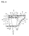
- the shock absorbing structure 10 of this embodiment having this type of structure is arranged in an installation space 54 between the ceiling lining 50 and the roof panel 52 as shown, for example, in Fig. 4.
- the plurality of shock absorbing members 12 are positioned with end surfaces, that are opposite to the top wall 18, in contact with a lower surface of the roof panel 52 facing the top portion 51 of the ceiling lining 50, at an end surface of a side connecting with the connecting bodies 14.
- the top wall 18 of each shock absorbing member 12 is brought into contact with an inner surface (upper surface) of the top portion 51 of the ceiling lining 50 facing the roof panel 52, or positioned separate from the inner surface of the top portion 51 by a small gap.
- each of the plurality of spacer members 30 attached to the plurality of connecting bodies 14 has the contact plate section 36 extending from the connecting body along the lower surface of the roof panel 52 towards an end section of the leg portion 53 of the ceiling lining 50, and the tip end of the contact plate section 36 is arranged in a state abutting contact with the inner surface of the end section of the leg portion 53 of the ceiling lining 50.
- the shock absorbing structure 10 is positioned at a fixed position inside the installation space 54 between the ceiling lining 50 and the roof panel 52 in a state where the extending direction of each side wall 20 of the tubular bodies 16 of the plurality of shock absorbing members is the same as the shock-receiving direction.
- each side wall 20 of the tubular bodies 16 of each shock absorbing member 12 is efficiently subjected to the buckling deformation in the height direction, and as a result sufficient shock absorbing performance is demonstrated in a stable manner.
- each spacer member 30 in a state fixed to the roof panel 52 inside the installation space 54, the contact plate section 36 of each spacer member 30 is brought into contact at the tip end section thereof with the inner surface of the end section of the leg portion 53 of the ceiling lining 50, and the top wall 18 of each shock absorbing member 12 is either brought into contact with the top portion 51 of the ceiling lining 50 or positioned facing the top portion 51 leaving a small gap therebetween.
- each shock absorbing member 12 there is absolutely no structure on each shock absorbing member 12 to attach the spacer member 30. Therefore, differing from the structure where a spacer member is attached to each shock absorbing member as disclosed, for example, in JP-A-2004-189120 , there is no formation whatsoever of corner sections or thick-walled sections that are squared off in order to attach the spacer member to each shock absorbing member 12, which may excessively increase the rigidity of each shock absorbing member 12 or reduce the shock absorbing stroke.
- this shock absorbing structure 10 is constructed with an integral component comprising the plurality of shock absorbing members 12 and the plurality of connecting bodies 14, to which a plurality of separately formed spacer members 30 are attached. Therefore, in the event that the whole of the shock absorbing structure is made by die molding, the integral component comprising the shock absorbing members 12 and the connecting bodies 14, and each of the spacer members 30, can be formed using separate molds, and as a result there can be used small and inexpensive items as those molds. As a result, the manufacturing cost of the shock absorbing structure 10 is kept as low as possible.
- the spacer member 30 is formed of a plate member
- the contact plate section 36 formed of a part of the spacer member 30 extends from the connecting body 14 in a direction perpendicular to the shock-receiving direction, and the tip end section of the contact plate section 36 is positioned in contact with the end section of the ceiling lining 50, so that there is effectively prevented a situation where the spacer member 30 hinders the deformation of each shock absorbing member 12 due to the application of the shock, and as a result there can be stably assured the sufficient shock absorbing performance.
- the number of the shock absorbing members 12 is not limited at all as long as the number is plural, and can be appropriately changed depending on the size of the installation space 54 or the size of the shock absorbing members 12 themselves, etc.
- the shape of the shock absorbing member is also not particularly limited.
- the shock absorbing member 12 has a shape that is smaller than any of various installation spaces that differ in size depending on the types of the vehicle interior component and the body structural component, so as to have a structure such that the shock is absorbed to at least a predetermined extent by being installed in any of these various sized installation spaces leaving the gap between the vehicle interior component and the body structural component, and by being deformed as a result of the outwardly applied shock.
- this type of structure it is possible to use a single general-purpose shock absorbing member for any shape of installation space. This shock absorbing structure therefore eliminates the need to carry out additional work in order to individually ascertain, at the design stage whether or not the shock absorbing member will exhibit the sufficient shock absorbing performance when respectively fitted into the various sized installation spaces.
- shock absorbing member 12 well known rib structures or various well-known structures for absorbing the shock formed by using a material other than the synthetic resin material can also be adopted as the shock absorbing member 12.
- the spacer member 30 is formed of the plate member having a shape according to the part of the gap 56 formed between the ceiling lining 50 and the shock absorbing member 12, but the spacer member may, for example, have a solid structure other than the plate shaped arrangement corresponding to the whole or a part of the gap 56, as disclosed in JP-A-2004-189120 .
- the spacer member 30 is made of the plate member, the overall or partial shape of the spacer member 30 and the direction of the extension of the spacer member 30 from the connecting body 14 etc. are not limited at all.
- spacer member 30 there is also no absolute necessity for the spacer member 30 to be attached to each of the plurality of connecting bodies 14.
- the attachment position of the spacer member 30 to the connecting body 14 is also not particularly limited.
- the attachment structure of the spacer members 30 to the connecting body 14 is not limited to the illustrated manner, and depending on the situation the spacer member 30 may have an integrated formation with the connecting body 14 such that the spacer member 30 cannot be removed from the connecting body 14.
- this engaging means can also be constructed using a member that is independent of the spacer member and the connecting body.
- the structure of the connecting body 14 can also have any configuration provided that the connecting body can connect the plurality of shock absorbing members.
- the illustrated embodiment of the invention has the structure arranged for the installation space 54 between the ceiling lining 50 and the roof panel 52 of the vehicle, it is to be understood that the present invention can also be advantageously applied to a shock absorbing structure arranged in an installation space between the vehicle interior components other than the ceiling lining and the body structural component positioned opposite to the vehicle compartment side of the interior component, or applied to a shock absorbing structure arranged in a vehicle other than an automobile.
Landscapes
- Engineering & Computer Science (AREA)
- Mechanical Engineering (AREA)
- Vibration Dampers (AREA)
- Vehicle Interior And Exterior Ornaments, Soundproofing, And Insulation (AREA)
Applications Claiming Priority (1)
| Application Number | Priority Date | Filing Date | Title |
|---|---|---|---|
| JP2006170722A JP4227153B2 (ja) | 2006-06-20 | 2006-06-20 | 車両用衝撃吸収構造体 |
Publications (3)
| Publication Number | Publication Date |
|---|---|
| EP1873021A2 true EP1873021A2 (de) | 2008-01-02 |
| EP1873021A3 EP1873021A3 (de) | 2009-07-01 |
| EP1873021B1 EP1873021B1 (de) | 2010-06-30 |
Family
ID=38525307
Family Applications (1)
| Application Number | Title | Priority Date | Filing Date |
|---|---|---|---|
| EP07251141A Not-in-force EP1873021B1 (de) | 2006-06-20 | 2007-03-19 | Stossabsorbierende Struktur für Fahrzeug |
Country Status (5)
| Country | Link |
|---|---|
| US (1) | US7448672B2 (de) |
| EP (1) | EP1873021B1 (de) |
| JP (1) | JP4227153B2 (de) |
| AT (1) | ATE472441T1 (de) |
| DE (1) | DE602007007397D1 (de) |
Families Citing this family (1)
| Publication number | Priority date | Publication date | Assignee | Title |
|---|---|---|---|---|
| CN104334911B (zh) * | 2012-04-05 | 2019-04-30 | 京洛株式会社 | 膝垫构件 |
Family Cites Families (19)
| Publication number | Priority date | Publication date | Assignee | Title |
|---|---|---|---|---|
| JP3052766B2 (ja) * | 1994-02-22 | 2000-06-19 | トヨタ自動車株式会社 | 自動車の内装材による衝撃エネルギ吸収構造 |
| JP3000898B2 (ja) * | 1995-07-12 | 2000-01-17 | トヨタ自動車株式会社 | 自動車の衝撃エネルギ吸収構造 |
| CA2202226C (en) * | 1996-04-10 | 2000-01-04 | Yoshinori Noritake | Impact energy absorbing structure of vehicle upper portion of automobile |
| JPH11180236A (ja) | 1997-12-24 | 1999-07-06 | Toyota Motor Corp | 自動車の車体上部におけるエネルギ吸収材の取付構造 |
| US6250711B1 (en) * | 1998-07-31 | 2001-06-26 | Toyota Jidosha Kabushiki Kaisha | Energy absorber securing structure and method |
| JP3097684B2 (ja) * | 1999-01-14 | 2000-10-10 | トヨタ自動車株式会社 | 自動車の車体上部の衝撃エネルギ吸収構造 |
| JP3543939B2 (ja) | 1999-12-03 | 2004-07-21 | 日本プラスト株式会社 | ガーニッシュ構造 |
| JP4211178B2 (ja) | 2000-01-28 | 2009-01-21 | 株式会社豊田自動織機 | 自動車の車体 |
| US6467834B1 (en) * | 2000-02-11 | 2002-10-22 | L&L Products | Structural reinforcement system for automotive vehicles |
| US6217061B1 (en) * | 2000-02-18 | 2001-04-17 | Daimlerchrysler Corporation | Airbag system within impact countermeasures |
| JP2002166804A (ja) * | 2000-12-01 | 2002-06-11 | Kojima Press Co Ltd | 車両用衝撃吸収構造体及びそれを用いた車両用内装部品の衝撃吸収構造 |
| DE10063339C1 (de) * | 2000-12-19 | 2001-12-06 | Porsche Ag | Energieabsorbierendes Deformationselement |
| GB0211775D0 (en) * | 2002-05-23 | 2002-07-03 | L & L Products Inc | Multi segment parts |
| JP3967647B2 (ja) * | 2002-08-28 | 2007-08-29 | 小島プレス工業株式会社 | 車両用衝撃吸収構造体 |
| AU2003257809A1 (en) * | 2002-10-31 | 2004-05-25 | Kyoraku Co., Ltd. | Impact absorbing body for vehicle |
| JP2004189120A (ja) | 2002-12-12 | 2004-07-08 | Kojima Press Co Ltd | 車両用衝撃吸収構造体 |
| JP4342823B2 (ja) * | 2003-04-09 | 2009-10-14 | 小島プレス工業株式会社 | 車両用衝撃吸収構造体 |
| DE60307487T2 (de) * | 2003-12-19 | 2007-03-08 | Grupo Antolin-Ingenieria S.A. | Modulare Struktur zur Energieaufnahme beim Kopfaufprall auf Fahrzeuginnenteile |
| JP4531468B2 (ja) * | 2004-07-14 | 2010-08-25 | 小島プレス工業株式会社 | 車両用衝撃吸収構造体及びその取付構造 |
-
2006
- 2006-06-20 JP JP2006170722A patent/JP4227153B2/ja not_active Expired - Fee Related
-
2007
- 2007-02-27 US US11/679,400 patent/US7448672B2/en not_active Expired - Fee Related
- 2007-03-19 DE DE602007007397T patent/DE602007007397D1/de active Active
- 2007-03-19 EP EP07251141A patent/EP1873021B1/de not_active Not-in-force
- 2007-03-19 AT AT07251141T patent/ATE472441T1/de not_active IP Right Cessation
Also Published As
| Publication number | Publication date |
|---|---|
| EP1873021B1 (de) | 2010-06-30 |
| DE602007007397D1 (de) | 2010-08-12 |
| US20070290523A1 (en) | 2007-12-20 |
| JP4227153B2 (ja) | 2009-02-18 |
| ATE472441T1 (de) | 2010-07-15 |
| JP2008001162A (ja) | 2008-01-10 |
| US7448672B2 (en) | 2008-11-11 |
| EP1873021A3 (de) | 2009-07-01 |
Similar Documents
| Publication | Publication Date | Title |
|---|---|---|
| US8052184B2 (en) | Crashbox and damping arrangement with crashbox | |
| JP2002166804A (ja) | 車両用衝撃吸収構造体及びそれを用いた車両用内装部品の衝撃吸収構造 | |
| EP2062787B1 (de) | Stoßdämpfungsstruktur für ein Fahrzeug | |
| US7954883B2 (en) | Energy-absorbing deformation element for a vehicle | |
| KR101143702B1 (ko) | 자동차용 범퍼 빔 | |
| KR20130042597A (ko) | 차량용 범퍼 | |
| US10457238B2 (en) | Impact absorber | |
| KR20010094988A (ko) | 차량의 펜더 구조 | |
| KR20180049833A (ko) | 자동차용 fmh 충격 감소용 플레이트 | |
| JP3967647B2 (ja) | 車両用衝撃吸収構造体 | |
| KR102334108B1 (ko) | 자동차의 헤드 라이너에 장착되는 fmh 모듈 | |
| US6299196B1 (en) | Air bag apparatus | |
| US9598110B2 (en) | Vehicle storage compartment assembly | |
| EP1873021B1 (de) | Stossabsorbierende Struktur für Fahrzeug | |
| US20180257596A1 (en) | Impact absorber | |
| JP2009208590A (ja) | ステアリングメンバ取付構造 | |
| JP2004058948A (ja) | 衝撃吸収ブラケット | |
| JP4063019B2 (ja) | 車両用衝撃吸収構造体 | |
| JP2004189120A (ja) | 車両用衝撃吸収構造体 | |
| JP4342823B2 (ja) | 車両用衝撃吸収構造体 | |
| KR20220102020A (ko) | 자동차용 fmh 플레이트 | |
| JP7567654B2 (ja) | 乗物用内装材 | |
| JP2020019317A (ja) | ピラーガーニッシュ | |
| KR20030088778A (ko) | 스포츠유틸리티 차량의 리어 필라부 결합구조 | |
| JP2025117982A (ja) | 車体構成部材の締結構造 |
Legal Events
| Date | Code | Title | Description |
|---|---|---|---|
| PUAI | Public reference made under article 153(3) epc to a published international application that has entered the european phase |
Free format text: ORIGINAL CODE: 0009012 |
|
| AK | Designated contracting states |
Kind code of ref document: A2 Designated state(s): AT BE BG CH CY CZ DE DK EE ES FI FR GB GR HU IE IS IT LI LT LU LV MC MT NL PL PT RO SE SI SK TR |
|
| AX | Request for extension of the european patent |
Extension state: AL BA HR MK YU |
|
| PUAL | Search report despatched |
Free format text: ORIGINAL CODE: 0009013 |
|
| AK | Designated contracting states |
Kind code of ref document: A3 Designated state(s): AT BE BG CH CY CZ DE DK EE ES FI FR GB GR HU IE IS IT LI LT LU LV MC MT NL PL PT RO SE SI SK TR |
|
| AX | Request for extension of the european patent |
Extension state: AL BA HR MK RS |
|
| 17P | Request for examination filed |
Effective date: 20090910 |
|
| GRAP | Despatch of communication of intention to grant a patent |
Free format text: ORIGINAL CODE: EPIDOSNIGR1 |
|
| AKX | Designation fees paid |
Designated state(s): AT BE BG CH CY CZ DE DK EE ES FI FR GB GR HU IE IS IT LI LT LU LV MC MT NL PL PT RO SE SI SK TR |
|
| GRAS | Grant fee paid |
Free format text: ORIGINAL CODE: EPIDOSNIGR3 |
|
| GRAA | (expected) grant |
Free format text: ORIGINAL CODE: 0009210 |
|
| AK | Designated contracting states |
Kind code of ref document: B1 Designated state(s): AT BE BG CH CY CZ DE DK EE ES FI FR GB GR HU IE IS IT LI LT LU LV MC MT NL PL PT RO SE SI SK TR |
|
| REG | Reference to a national code |
Ref country code: CH Ref legal event code: EP Ref country code: GB Ref legal event code: FG4D |
|
| REG | Reference to a national code |
Ref country code: IE Ref legal event code: FG4D |
|
| REF | Corresponds to: |
Ref document number: 602007007397 Country of ref document: DE Date of ref document: 20100812 Kind code of ref document: P |
|
| REG | Reference to a national code |
Ref country code: NL Ref legal event code: VDEP Effective date: 20100630 |
|
| PG25 | Lapsed in a contracting state [announced via postgrant information from national office to epo] |
Ref country code: SE Free format text: LAPSE BECAUSE OF FAILURE TO SUBMIT A TRANSLATION OF THE DESCRIPTION OR TO PAY THE FEE WITHIN THE PRESCRIBED TIME-LIMIT Effective date: 20100630 Ref country code: LT Free format text: LAPSE BECAUSE OF FAILURE TO SUBMIT A TRANSLATION OF THE DESCRIPTION OR TO PAY THE FEE WITHIN THE PRESCRIBED TIME-LIMIT Effective date: 20100630 |
|
| LTIE | Lt: invalidation of european patent or patent extension |
Effective date: 20100630 |
|
| PG25 | Lapsed in a contracting state [announced via postgrant information from national office to epo] |
Ref country code: AT Free format text: LAPSE BECAUSE OF FAILURE TO SUBMIT A TRANSLATION OF THE DESCRIPTION OR TO PAY THE FEE WITHIN THE PRESCRIBED TIME-LIMIT Effective date: 20100630 Ref country code: SI Free format text: LAPSE BECAUSE OF FAILURE TO SUBMIT A TRANSLATION OF THE DESCRIPTION OR TO PAY THE FEE WITHIN THE PRESCRIBED TIME-LIMIT Effective date: 20100630 Ref country code: FI Free format text: LAPSE BECAUSE OF FAILURE TO SUBMIT A TRANSLATION OF THE DESCRIPTION OR TO PAY THE FEE WITHIN THE PRESCRIBED TIME-LIMIT Effective date: 20100630 Ref country code: LV Free format text: LAPSE BECAUSE OF FAILURE TO SUBMIT A TRANSLATION OF THE DESCRIPTION OR TO PAY THE FEE WITHIN THE PRESCRIBED TIME-LIMIT Effective date: 20100630 |
|
| PG25 | Lapsed in a contracting state [announced via postgrant information from national office to epo] |
Ref country code: PL Free format text: LAPSE BECAUSE OF FAILURE TO SUBMIT A TRANSLATION OF THE DESCRIPTION OR TO PAY THE FEE WITHIN THE PRESCRIBED TIME-LIMIT Effective date: 20100630 |
|
| PG25 | Lapsed in a contracting state [announced via postgrant information from national office to epo] |
Ref country code: NL Free format text: LAPSE BECAUSE OF FAILURE TO SUBMIT A TRANSLATION OF THE DESCRIPTION OR TO PAY THE FEE WITHIN THE PRESCRIBED TIME-LIMIT Effective date: 20100630 Ref country code: EE Free format text: LAPSE BECAUSE OF FAILURE TO SUBMIT A TRANSLATION OF THE DESCRIPTION OR TO PAY THE FEE WITHIN THE PRESCRIBED TIME-LIMIT Effective date: 20100630 |
|
| PG25 | Lapsed in a contracting state [announced via postgrant information from national office to epo] |
Ref country code: CZ Free format text: LAPSE BECAUSE OF FAILURE TO SUBMIT A TRANSLATION OF THE DESCRIPTION OR TO PAY THE FEE WITHIN THE PRESCRIBED TIME-LIMIT Effective date: 20100630 Ref country code: SK Free format text: LAPSE BECAUSE OF FAILURE TO SUBMIT A TRANSLATION OF THE DESCRIPTION OR TO PAY THE FEE WITHIN THE PRESCRIBED TIME-LIMIT Effective date: 20100630 Ref country code: RO Free format text: LAPSE BECAUSE OF FAILURE TO SUBMIT A TRANSLATION OF THE DESCRIPTION OR TO PAY THE FEE WITHIN THE PRESCRIBED TIME-LIMIT Effective date: 20100630 Ref country code: PT Free format text: LAPSE BECAUSE OF FAILURE TO SUBMIT A TRANSLATION OF THE DESCRIPTION OR TO PAY THE FEE WITHIN THE PRESCRIBED TIME-LIMIT Effective date: 20101102 Ref country code: IS Free format text: LAPSE BECAUSE OF FAILURE TO SUBMIT A TRANSLATION OF THE DESCRIPTION OR TO PAY THE FEE WITHIN THE PRESCRIBED TIME-LIMIT Effective date: 20101030 Ref country code: CY Free format text: LAPSE BECAUSE OF FAILURE TO SUBMIT A TRANSLATION OF THE DESCRIPTION OR TO PAY THE FEE WITHIN THE PRESCRIBED TIME-LIMIT Effective date: 20100630 Ref country code: BE Free format text: LAPSE BECAUSE OF FAILURE TO SUBMIT A TRANSLATION OF THE DESCRIPTION OR TO PAY THE FEE WITHIN THE PRESCRIBED TIME-LIMIT Effective date: 20100630 |
|
| PG25 | Lapsed in a contracting state [announced via postgrant information from national office to epo] |
Ref country code: IT Free format text: LAPSE BECAUSE OF FAILURE TO SUBMIT A TRANSLATION OF THE DESCRIPTION OR TO PAY THE FEE WITHIN THE PRESCRIBED TIME-LIMIT Effective date: 20100630 |
|
| PG25 | Lapsed in a contracting state [announced via postgrant information from national office to epo] |
Ref country code: DK Free format text: LAPSE BECAUSE OF FAILURE TO SUBMIT A TRANSLATION OF THE DESCRIPTION OR TO PAY THE FEE WITHIN THE PRESCRIBED TIME-LIMIT Effective date: 20100630 Ref country code: GR Free format text: LAPSE BECAUSE OF FAILURE TO SUBMIT A TRANSLATION OF THE DESCRIPTION OR TO PAY THE FEE WITHIN THE PRESCRIBED TIME-LIMIT Effective date: 20101001 |
|
| PLBE | No opposition filed within time limit |
Free format text: ORIGINAL CODE: 0009261 |
|
| STAA | Information on the status of an ep patent application or granted ep patent |
Free format text: STATUS: NO OPPOSITION FILED WITHIN TIME LIMIT |
|
| 26N | No opposition filed |
Effective date: 20110331 |
|
| PG25 | Lapsed in a contracting state [announced via postgrant information from national office to epo] |
Ref country code: ES Free format text: LAPSE BECAUSE OF FAILURE TO SUBMIT A TRANSLATION OF THE DESCRIPTION OR TO PAY THE FEE WITHIN THE PRESCRIBED TIME-LIMIT Effective date: 20101011 |
|
| REG | Reference to a national code |
Ref country code: DE Ref legal event code: R097 Ref document number: 602007007397 Country of ref document: DE Effective date: 20110330 |
|
| PGFP | Annual fee paid to national office [announced via postgrant information from national office to epo] |
Ref country code: GB Payment date: 20110221 Year of fee payment: 5 Ref country code: DE Payment date: 20110223 Year of fee payment: 5 |
|
| PG25 | Lapsed in a contracting state [announced via postgrant information from national office to epo] |
Ref country code: MC Free format text: LAPSE BECAUSE OF NON-PAYMENT OF DUE FEES Effective date: 20110331 |
|
| REG | Reference to a national code |
Ref country code: CH Ref legal event code: PL |
|
| REG | Reference to a national code |
Ref country code: FR Ref legal event code: ST Effective date: 20111130 |
|
| PG25 | Lapsed in a contracting state [announced via postgrant information from national office to epo] |
Ref country code: MT Free format text: LAPSE BECAUSE OF FAILURE TO SUBMIT A TRANSLATION OF THE DESCRIPTION OR TO PAY THE FEE WITHIN THE PRESCRIBED TIME-LIMIT Effective date: 20100630 |
|
| REG | Reference to a national code |
Ref country code: IE Ref legal event code: MM4A |
|
| PG25 | Lapsed in a contracting state [announced via postgrant information from national office to epo] |
Ref country code: IE Free format text: LAPSE BECAUSE OF NON-PAYMENT OF DUE FEES Effective date: 20110319 Ref country code: FR Free format text: LAPSE BECAUSE OF NON-PAYMENT OF DUE FEES Effective date: 20110331 Ref country code: CH Free format text: LAPSE BECAUSE OF NON-PAYMENT OF DUE FEES Effective date: 20110331 Ref country code: LI Free format text: LAPSE BECAUSE OF NON-PAYMENT OF DUE FEES Effective date: 20110331 |
|
| GBPC | Gb: european patent ceased through non-payment of renewal fee |
Effective date: 20120319 |
|
| PG25 | Lapsed in a contracting state [announced via postgrant information from national office to epo] |
Ref country code: GB Free format text: LAPSE BECAUSE OF NON-PAYMENT OF DUE FEES Effective date: 20120319 |
|
| REG | Reference to a national code |
Ref country code: DE Ref legal event code: R119 Ref document number: 602007007397 Country of ref document: DE Effective date: 20121002 |
|
| PG25 | Lapsed in a contracting state [announced via postgrant information from national office to epo] |
Ref country code: LU Free format text: LAPSE BECAUSE OF NON-PAYMENT OF DUE FEES Effective date: 20110319 |
|
| PG25 | Lapsed in a contracting state [announced via postgrant information from national office to epo] |
Ref country code: TR Free format text: LAPSE BECAUSE OF FAILURE TO SUBMIT A TRANSLATION OF THE DESCRIPTION OR TO PAY THE FEE WITHIN THE PRESCRIBED TIME-LIMIT Effective date: 20100630 Ref country code: BG Free format text: LAPSE BECAUSE OF FAILURE TO SUBMIT A TRANSLATION OF THE DESCRIPTION OR TO PAY THE FEE WITHIN THE PRESCRIBED TIME-LIMIT Effective date: 20100930 |
|
| PG25 | Lapsed in a contracting state [announced via postgrant information from national office to epo] |
Ref country code: HU Free format text: LAPSE BECAUSE OF FAILURE TO SUBMIT A TRANSLATION OF THE DESCRIPTION OR TO PAY THE FEE WITHIN THE PRESCRIBED TIME-LIMIT Effective date: 20100630 |
|
| PG25 | Lapsed in a contracting state [announced via postgrant information from national office to epo] |
Ref country code: DE Free format text: LAPSE BECAUSE OF NON-PAYMENT OF DUE FEES Effective date: 20121002 |