EP1873335A2 - Elektrische Schaltungsanordnung - Google Patents
Elektrische Schaltungsanordnung Download PDFInfo
- Publication number
- EP1873335A2 EP1873335A2 EP20070252456 EP07252456A EP1873335A2 EP 1873335 A2 EP1873335 A2 EP 1873335A2 EP 20070252456 EP20070252456 EP 20070252456 EP 07252456 A EP07252456 A EP 07252456A EP 1873335 A2 EP1873335 A2 EP 1873335A2
- Authority
- EP
- European Patent Office
- Prior art keywords
- power source
- switch
- circuit arrangement
- electrical circuit
- unlatching
- Prior art date
- Legal status (The legal status is an assumption and is not a legal conclusion. Google has not performed a legal analysis and makes no representation as to the accuracy of the status listed.)
- Withdrawn
Links
- 239000003990 capacitor Substances 0.000 claims description 25
- 230000001419 dependent effect Effects 0.000 claims description 3
- 238000013270 controlled release Methods 0.000 claims 1
- 230000007257 malfunction Effects 0.000 description 2
- 206010039203 Road traffic accident Diseases 0.000 description 1
- 238000007599 discharging Methods 0.000 description 1
- 238000012432 intermediate storage Methods 0.000 description 1
Images

Classifications
-
- E—FIXED CONSTRUCTIONS
- E05—LOCKS; KEYS; WINDOW OR DOOR FITTINGS; SAFES
- E05B—LOCKS; ACCESSORIES THEREFOR; HANDCUFFS
- E05B77/00—Vehicle locks characterised by special functions or purposes
- E05B77/22—Functions related to actuation of locks from the passenger compartment of the vehicle
- E05B77/30—Functions related to actuation of locks from the passenger compartment of the vehicle allowing opening by means of an inner door handle, even if the door is locked
-
- E—FIXED CONSTRUCTIONS
- E05—LOCKS; KEYS; WINDOW OR DOOR FITTINGS; SAFES
- E05B—LOCKS; ACCESSORIES THEREFOR; HANDCUFFS
- E05B81/00—Power-actuated vehicle locks
- E05B81/54—Electrical circuits
-
- E—FIXED CONSTRUCTIONS
- E05—LOCKS; KEYS; WINDOW OR DOOR FITTINGS; SAFES
- E05B—LOCKS; ACCESSORIES THEREFOR; HANDCUFFS
- E05B81/00—Power-actuated vehicle locks
- E05B81/54—Electrical circuits
- E05B81/64—Monitoring or sensing, e.g. by using switches or sensors
- E05B81/76—Detection of handle operation; Detection of a user approaching a handle; Electrical switching actions performed by door handles
-
- E—FIXED CONSTRUCTIONS
- E05—LOCKS; KEYS; WINDOW OR DOOR FITTINGS; SAFES
- E05B—LOCKS; ACCESSORIES THEREFOR; HANDCUFFS
- E05B81/00—Power-actuated vehicle locks
- E05B81/54—Electrical circuits
- E05B81/80—Electrical circuits characterised by the power supply; Emergency power operation
- E05B81/82—Electrical circuits characterised by the power supply; Emergency power operation using batteries other than the vehicle main battery
-
- E—FIXED CONSTRUCTIONS
- E05—LOCKS; KEYS; WINDOW OR DOOR FITTINGS; SAFES
- E05B—LOCKS; ACCESSORIES THEREFOR; HANDCUFFS
- E05B81/00—Power-actuated vehicle locks
- E05B81/54—Electrical circuits
- E05B81/80—Electrical circuits characterised by the power supply; Emergency power operation
- E05B81/86—Electrical circuits characterised by the power supply; Emergency power operation using capacitors
-
- E—FIXED CONSTRUCTIONS
- E05—LOCKS; KEYS; WINDOW OR DOOR FITTINGS; SAFES
- E05B—LOCKS; ACCESSORIES THEREFOR; HANDCUFFS
- E05B77/00—Vehicle locks characterised by special functions or purposes
- E05B77/22—Functions related to actuation of locks from the passenger compartment of the vehicle
- E05B77/24—Functions related to actuation of locks from the passenger compartment of the vehicle preventing use of an inner door handle, sill button, lock knob or the like
- E05B77/26—Functions related to actuation of locks from the passenger compartment of the vehicle preventing use of an inner door handle, sill button, lock knob or the like specially adapted for child safety
-
- E—FIXED CONSTRUCTIONS
- E05—LOCKS; KEYS; WINDOW OR DOOR FITTINGS; SAFES
- E05B—LOCKS; ACCESSORIES THEREFOR; HANDCUFFS
- E05B77/00—Vehicle locks characterised by special functions or purposes
- E05B77/22—Functions related to actuation of locks from the passenger compartment of the vehicle
- E05B77/24—Functions related to actuation of locks from the passenger compartment of the vehicle preventing use of an inner door handle, sill button, lock knob or the like
- E05B77/28—Functions related to actuation of locks from the passenger compartment of the vehicle preventing use of an inner door handle, sill button, lock knob or the like for anti-theft purposes, e.g. double-locking or super-locking
-
- Y—GENERAL TAGGING OF NEW TECHNOLOGICAL DEVELOPMENTS; GENERAL TAGGING OF CROSS-SECTIONAL TECHNOLOGIES SPANNING OVER SEVERAL SECTIONS OF THE IPC; TECHNICAL SUBJECTS COVERED BY FORMER USPC CROSS-REFERENCE ART COLLECTIONS [XRACs] AND DIGESTS
- Y10—TECHNICAL SUBJECTS COVERED BY FORMER USPC
- Y10T—TECHNICAL SUBJECTS COVERED BY FORMER US CLASSIFICATION
- Y10T70/00—Locks
- Y10T70/50—Special application
- Y10T70/5889—For automotive vehicles
Definitions
- the present invention relates to an electric circuit arrangement for operating an unlatching actuator.
- the unlatching actuator may unlatch a door latch, in particular a vehicle door latch, more particularly a land vehicle door latch such as a car passenger door.
- PCT/CA2004/001958 shows an electronic latch arrangement in which power from a main power source is used to unlatch the vehicle doors via an unlatching actuator.
- the main power source becomes disconnected from the unlatching actuator (such as following a vehicle crash) the power required for unlatching is drawn from a back-up battery contained within the circuit.
- the circuit further includes a bank of capacitors connected between the main power source, the back-up battery and a motor which drives the unlatching actuator. Under normal conditions the capacitors are charged by the main power source, and in the "emergency" condition (e.g. following a crash) the capacitors are charged by the back-up battery.
- the energy required by the motor to drive the unlatching actuator is provided by discharging the capacitors.
- the motor is directly connected to the capacitiors, but is not directly connected to or directly powered by the main battery or the back-up battery.
- energy is only ever drawn from the capacitor.
- no energy is drawn from the main power source or from the backup battery.
- Power is only drawn from the main power source or from the backup battery at times other than when unlatching is occurring. This is because it is not possible to simultaneously discharge the capacitor for unlatching and recharge it.
- the electronic circuit of PCT/CA2004/001958 further includes a microcontroller which controls the components of the circuit as well as receiving signals from the inside and outside door handles of the vehicle for example.
- a microcontroller which controls the components of the circuit as well as receiving signals from the inside and outside door handles of the vehicle for example.
- the microcontroller draws a current from the main power source.
- "emergency” conditions the microcontroller continues to draw a current, initially from the capacitors and then from a regulator.
- the microcontroller is therefore operational under both normal and "emergency” conditions and is thus safety critical. It would be appreciated that, if, as a result of a vehicle crash, the micro controller is damaged, and rendered inoperative, it will not be possible to electrically release the doors since the release signal (as generated by operating either the inside door handle or the outside door handle) is transmitted via the microcontroller.
- the electric circuit arrangement of the present invention includes two power sources; a primary power source for unlatching under normal conditions, and a secondary or back-up power source for unlatching under "emergency" conditions i.e. when the primary power source is inoperable, such as might occur following a vehicle crash.
- the components are mounted on a vehicle 8 (shown schematically).
- the logic controller controls the bypass switch, release switch and reset switch and receives signals from the inside handle switch and outside handle switch as will be described below.
- the inside handle switch will typically be mounted within easy reach of a vehicle occupant when seated.
- the inside handle switch may be mounted on the door adjacent to the seat or alternatively can be mounted on some fixed structure of the vehicle.
- the outside handle switch will typically be mounted on or adjacent an associated door.
- the unlatching actuator will typically be mounted adjacent an associated latch (not shown).
- the latch and associated striker (not shown) will together enable an associated door to be releasably closed.
- the latch may be mounted on the door with a striker being mounted on adjacent fixed structure of the vehicle such as a B post or a C post, or alternatively the striker may be mounted on the door and the latch may be mounted on adjacent fixed structure of the vehicle.
- Unlatching actuators, their associated latches, the associated striker, and their positioning on associated doors is well known and will not be further described.
- the primary power source 20 will typically be a vehicle main battery. Alternatively, or additionally, the primary power source may include a generator, such as an engine driven alternator.
- the secondary power source in this case is a capacitor, though in further embodiments it could be an alternative power source, such as a battery.
- the secondary power source is preferably charged by the primary power source.
- the bypass switch 24 is an electrically controlled switch having a pole P1, and terminals T1 and T2.
- the switch When the bypass switch is energised (as will be described below) the switch adopts a first switching condition in which pole P1 is electrically connected to terminal T1 (as shown in figure 1).
- the unlatching actuator When operation of the inside or outside door handle is sensed, the unlatching actuator will draw current from the logic controller 12 through terminal T1 of bypass switch 24, thereby enabling unlatching.
- bypass switch 24 When the bypass switch 24 is deenergised (as described below) it adopts a second switching condition in which pole P 1 is electrically connected to terminal T2 (as shown in figure 2). When operation of the inside or outside door handle is sensed, the unlatching actuator will draw current from the secondary power source, in this case capacitor 22, through terminal T2 of bypass switch 24, thereby enabling unlatching.
- Terminals T1 and T2 therefore both connect components within the circuit, and in both of the switching conditions described above the bypass switch acts to complete a circuit.
- Bypass switch 24 may be a relay.
- bypass switch 24 is a relay
- the relay consists of coil 36, contact 37 which connects pole P1 to either terminal T1 or T2, and spring 38 which biases contact 37 towards terminal T2.
- the bypass switch 24 is energised, current flows through coil 36 thereby generating a magnetic field which causes contact 37 to connect to terminal T1, against the biasing action of spring 38.
- Spring 38 is selected to be of a resilience such that it is overcome by the strength of the magnetic field when the bypass switch is energised.
- bypass switch 24 is deenergised, no current flows through coil 36 and therefore no magnetic field is generated. In the absence of a magnetic field, contact 37 connects to terminal T2 under the biasing action of spring 38.
- bypass switch Under normal conditions the bypass switch is energised by the logic controller 12 and the bypass switch adopts the first switching condition, that is the contact 37 connects pole P1 to terminal T1. Under "emergency" conditions the bypass switch is deenergised and the bypass switch adopts the second switching condition, that is the contact 37 connects pole P1 to terminal T2.
- Release switch 26 and reset switch 28 are similar to bypass switch 24 and include poles P1' and P2' respectively and terminals T1', T2', T1", T2" respectively.
- Release switch 26 and reset switch 28 may also be relays, and are shown schematically in figures 1 and 2.
- Release switch 26 comprises coil 40, contact 41 and spring 42.
- Reset switch 28 comprises coil 44, contact 45 and spring 46.
- release switch 26 When release switch 26 is energised by the logic controller 12, current flows through coil 40 thereby generating a magnetic field which causes contact 41 to connect to terminal T1', against the biasing action of spring 42. When the release switch 26 is deenergised, no current flows through coil 40 so no magnetic field is generated and contact 41 connects to terminal T2' under the biasing action of spring 42.
- bypass switch 24, release switch 26 and reset switch 28 are not limited to relays. Any kind of switch which adopts a first position when energised and a second position when deenergised may be used.
- the circuit also includes unidirectional electrical devices, in this case diodes 30, 32 and 34.
- the vehicle in normal operation access to and egress from the vehicle is controlled by the logic controller 12.
- the vehicle can have different security statuses, for example the vehicle can be locked, in which case actuation of the outside handle switch will not cause actuation of the unlatching actuator but actuation of the inside handle switch will cause actuation of the unlatching actuator.
- Examples of other security statuses are superlocked (also known as deadlocked), unlocked, child safety on, child safety off. Such security statuses are well known to those skilled in the art and will not be described further here.
- bypass switch is energised by the logic controller and adopts the first switching condition shown in figure 1.
- operation of an inside handle switch or an outside handle switch relies on the logic controller controlling the release switch 26 in an appropriate manner (dependent upon the security status) to operate the unlatching actuator.
- bypass switch 24 is deenergised (i.e. it is no longer energised by the logic controller) and the bypass switch automatically adopts the second switching configuration shown in figure 2.
- operation of either the inside handle switch or the outside handle switch allows the capacitor to discharge through the unlatching actuator and hence release the associated latch. It will be appreciated that such releasing of the latch is independent of the primary power source 20 and is also independent of the logic controller 12.
- the power is drawn from one of the primary and secondary power sources and is fed directly to the unlatching actuator.
- the power released from the primary power source or the secondary power source, in this case capacitor 22, is not fed to an intermediate storage device, for example a further capacitor for subsequent use when releasing the latch.
- the primary power source directly powers the unlatching actuator.
- the secondary power source directly powers the unlatching actuator.
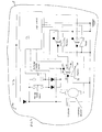
- figure 1 shows the system in normal operation when the primary power source is available at a power source and the logic controller is operating correctly. Under these circumstances the logic controller 12 energises the bypass switch 24 such that pole P 1 is connected to terminal T1.
- pole P1' is connected to terminal T2' (in view of the biasing action of spring 42) and pole P1" is connected to terminal T2" (in view of the biasing action of spring 46).
- the inside handle switch and outside handle switch are both in an open circuit position.
- Capacitor 22 is charged by the primary power source 20.
- the logic controller has predetermined security statuses and the vehicle operator can select one of the predetermined security statuses.
- the logic controller determines which of the inside handle switch or the outside handle switch have been operated.
- the logic controller compares the operation of the switch with the current security status of the latch to determine whether or not to energise the release switch 26.
- the logic controller will energise the coil 40 of the release switch 26 thereby momentarily connecting terminal T1' to pole P1'. This allows the unlatching actuator to be energised by the primary power source thereby unlatching the latch and enabling the door to be opened.
- the logic controller then deenergises the coil 40 of the release switch and energises the coil 44 of reset switch 28 to return the release actuator to its rest position.
- the reset switch is only energised for sufficient time to reset the unlatching actuator and is then deenergised by the logic controller. Subsequent closing of the door will then relatch the latch.
- the secondary power source in this case capacitor 22, remains charged. That is, none of the power required by the unlatching actuator is taken from the secondary power source under "normal” conditions. In other words, during "normal" unlatching the secondary power source is not discharged.
- the circuit adopts the configuration as shown in figure 2.
- this switch adopts the second switching configuration as shown in figure 2 wherein pole P1 is connected to terminal T2.
- the primary power source and the logic controller are therefore not "safety critical" components, so if they malfunction as the result of a crash for example, the vehicle doors can still be unlatched using power from the secondary power source.
- the secondary power source is a capacitor
- this "emergency" configuration will typically give a “one shot” operation of the unlatching actuator.
- the unlatching actuator can be actuated more than once.
- the system when the vehicle is parked and left unattended, the system may be configured to adopt the configuration as shown in figure 2, i.e. the bypass switch may not be energised in order to prevent depletion of the primary power source when the primary power source is a battery. Under these circumstances, it is preferable to discharge the secondary power source when it is a capacitor.
- the logic controller can additionally cause the capacitor to be drained. One way of draining the capacitor is to momentarily energise the reset switch thereby draining the capacitor through the unlatching actuator without actuating the latch.
- the logic controller can operate a switch (not shown) to isolate this secondary power source.
- This system is particularly applicable to the vehicle door latch system where manual unlatching means (such as inside door handles and outside door handles) are not present. Under these circumstances it is necessary to ensure that the vehicle can be unlatched in the event of a power failure whilst driving and that the control device, such as the logic controller cannot cause involuntary unlatching to take place. Under such circumstances, the security statuses can be determined by the software within the logic controller. Security statuses can be as follows:-
- the logic controller can define security statuses, but it can also define how those statuses change dependent upon actions taken by operators.
- the security statuses can be initially defined by buttons within the vehicle, or buttons or a sequence of button pushing on a remote locking device such as an infra red key fob device.
- a security setting has been defined by such a device that security setting can be changed either operation of the remote device or switches within the vehicle or alternatively the setting can be changed by operation of an inside handle or an outside handle.
- override unlocking operation can be provided for.
- operation of the outside switch will not open the door but operation of the inside switch will open the door.
- the logic controller is configured to provide override unlocking, then, starting with the locked front door, operation of the inside handle will open the door but will also change status of that door to unlocked so that when the door is subsequently closed, it is not locked. This is traditionally provided to ensure that keys or the like do not inadvertently get locked in the vehicle.
- Figures 1 and 2 show a vehicle 8 having an electric circuit arrangement 10 for controlling an unlatching actuator associated with a latch of a door having an associated inside handle switch and an outside handle switch.
- each door may have electric circuit arrangement shown in figures 1 and 2.
- each door may have electric circuit arrangement shown in figures 1 and 2.
- a vehicle has a plurality of doors
- the primary power source 20 it is advantageous for the primary power source 20 to be common to all doors. It is also advantageous for the logic controller 12 to be common to all doors.
- the secondary power source may be common to all doors.
- each door which is equipped with the circuit arrangement of figures 1 and 2 may have a dedicated secondary power source.
Landscapes
- Engineering & Computer Science (AREA)
- Power Engineering (AREA)
- Lock And Its Accessories (AREA)
Applications Claiming Priority (1)
| Application Number | Priority Date | Filing Date | Title |
|---|---|---|---|
| GB0612879A GB0612879D0 (en) | 2006-06-29 | 2006-06-29 | Electrical circuit arrangement |
Publications (1)
| Publication Number | Publication Date |
|---|---|
| EP1873335A2 true EP1873335A2 (de) | 2008-01-02 |
Family
ID=36888275
Family Applications (1)
| Application Number | Title | Priority Date | Filing Date |
|---|---|---|---|
| EP20070252456 Withdrawn EP1873335A2 (de) | 2006-06-29 | 2007-06-15 | Elektrische Schaltungsanordnung |
Country Status (4)
| Country | Link |
|---|---|
| US (1) | US7642669B2 (de) |
| EP (1) | EP1873335A2 (de) |
| CN (1) | CN101097633B (de) |
| GB (1) | GB0612879D0 (de) |
Cited By (1)
| Publication number | Priority date | Publication date | Assignee | Title |
|---|---|---|---|---|
| WO2021228741A1 (de) * | 2020-05-13 | 2021-11-18 | Brose Fahrzeugteile Se & Co. Kommanditgesellschaft, Bamberg | STEUERANORDNUNG FÜR DEN BETRIEB EINES KRAFFAHRZEUGSCHLIEßSYSTEMS |
Families Citing this family (45)
| Publication number | Priority date | Publication date | Assignee | Title |
|---|---|---|---|---|
| DE102008059104B4 (de) * | 2008-11-26 | 2011-03-10 | Audi Ag | Verfahren zur Steuerung eines Schließsystems eines Kraftfahrzeugs und Kraftfahrzeug |
| US9260882B2 (en) | 2009-03-12 | 2016-02-16 | Ford Global Technologies, Llc | Universal global latch system |
| US8534101B2 (en) * | 2010-02-22 | 2013-09-17 | GM Global Technology Operations LLC | Electronic unlatch system for vehicle door |
| US8466652B2 (en) | 2011-01-12 | 2013-06-18 | Arvinmeritor Technology, Llc | Method and apparatus for generating a charging circuit |
| US9551166B2 (en) * | 2011-11-02 | 2017-01-24 | Ford Global Technologies, Llc | Electronic interior door release system |
| US8924087B2 (en) * | 2012-05-15 | 2014-12-30 | GM Global Technology Operations LLC | Motor vehicle having a centralized door locking system |
| US9957737B2 (en) | 2012-06-29 | 2018-05-01 | Ford Global Technologies, Llc | Flush-mounted door handle for vehicles |
| US8958948B2 (en) * | 2012-09-27 | 2015-02-17 | GM Global Technology Operations LLC | Methods and systems for controlling an actuator of a vehicle latch |
| DE112013006196T5 (de) | 2012-12-24 | 2015-09-10 | Magna Closures Inc. | Unfallmanagementsystem und Verfahren in einem elektronischen Schloss einer Kraftfahrzeug-Schließvorrichtung |
| US8825287B2 (en) * | 2013-01-09 | 2014-09-02 | GM Global Technology Operations LLC | Vehicle door latch system and method |
| US9593514B2 (en) | 2013-02-18 | 2017-03-14 | Ford Global Technologies, Llc | Seamless exterior handle for a vehicle door |
| CN105324865B (zh) | 2013-03-12 | 2017-11-17 | 品谱股份有限公司 | 具有多源能量收集回路的电子锁具 |
| US9416565B2 (en) | 2013-11-21 | 2016-08-16 | Ford Global Technologies, Llc | Piezo based energy harvesting for e-latch systems |
| US10119308B2 (en) | 2014-05-13 | 2018-11-06 | Ford Global Technologies, Llc | Powered latch system for vehicle doors and control system therefor |
| US9903142B2 (en) | 2014-05-13 | 2018-02-27 | Ford Global Technologies, Llc | Vehicle door handle and powered latch system |
| US10323442B2 (en) | 2014-05-13 | 2019-06-18 | Ford Global Technologies, Llc | Electronic safe door unlatching operations |
| US10273725B2 (en) | 2014-05-13 | 2019-04-30 | Ford Global Technologies, Llc | Customer coaching method for location of E-latch backup handles |
| CN104123773A (zh) * | 2014-06-30 | 2014-10-29 | 周运雪 | 指纹识别无线遥控防盗门锁 |
| US9909344B2 (en) | 2014-08-26 | 2018-03-06 | Ford Global Technologies, Llc | Keyless vehicle door latch system with powered backup unlock feature |
| US9518408B1 (en) | 2015-05-21 | 2016-12-13 | Ford Global Technologies, Llc | Alternate backup entry for vehicles |
| DE102015108739A1 (de) * | 2015-06-02 | 2016-12-08 | Kiekert Ag | Verfahren zur Steuerung eines Kraftfahrzeugtürverschlusses |
| US10294699B2 (en) * | 2015-09-29 | 2019-05-21 | Faraday&Future Inc. | Electric door release system |
| US9725069B2 (en) | 2015-10-12 | 2017-08-08 | Ford Global Technologies, Llc | Keyless vehicle systems |
| US10227810B2 (en) | 2016-08-03 | 2019-03-12 | Ford Global Technologies, Llc | Priority driven power side door open/close operations |
| US10087671B2 (en) | 2016-08-04 | 2018-10-02 | Ford Global Technologies, Llc | Powered driven door presenter for vehicle doors |
| US10329823B2 (en) | 2016-08-24 | 2019-06-25 | Ford Global Technologies, Llc | Anti-pinch control system for powered vehicle doors |
| US10458171B2 (en) | 2016-09-19 | 2019-10-29 | Ford Global Technologies, Llc | Anti-pinch logic for door opening actuator |
| US10604970B2 (en) | 2017-05-04 | 2020-03-31 | Ford Global Technologies, Llc | Method to detect end-of-life in latches |
| US11053714B2 (en) * | 2017-09-14 | 2021-07-06 | Panasonic Intellectual Property Management Co., Ltd. | Door latch power supply device, door latch power supply system, and vehicle using same |
| US10907386B2 (en) | 2018-06-07 | 2021-02-02 | Ford Global Technologies, Llc | Side door pushbutton releases |
| US11319732B2 (en) * | 2018-08-17 | 2022-05-03 | Ford Global Technologies, Llc | Pre-fluxing motors of vehicle door e-latches |
| DE102019112874A1 (de) * | 2019-05-16 | 2020-11-19 | Schaeffler Technologies AG & Co. KG | Gewährleistung eines notfallbetriebs eines aktors |
| US11959315B2 (en) | 2019-05-23 | 2024-04-16 | Magna Closures Inc. | Latch assembly with hybrid backup energy source |
| CN110206408B (zh) * | 2019-07-08 | 2023-08-08 | 广东好太太智能家居有限公司 | 一种带稳定电控系统的智能门锁 |
| CN110525375B (zh) * | 2019-09-12 | 2021-08-20 | 上海科世达-华阳汽车电器有限公司 | 一种车辆及其解锁设备 |
| US11549287B2 (en) * | 2019-12-04 | 2023-01-10 | Kiekert Ag | Door latch, in particular motor vehicle door latch |
| US11668120B2 (en) * | 2020-07-27 | 2023-06-06 | Rivian Ip Holdings, Llc | Automatic door release with mechanical linkage |
| US12546150B2 (en) * | 2021-01-07 | 2026-02-10 | Ford Global Technologies, Llc | Door assembly for motor vehicle |
| US12077996B2 (en) * | 2021-03-08 | 2024-09-03 | Magna Closures Inc. | Closure latch assembly and electronic control systems for the closure latch assembly |
| JP7698968B2 (ja) * | 2021-03-31 | 2025-06-26 | ミネベアミツミ株式会社 | 車両用ドアラッチ装置 |
| DE102021111853A1 (de) * | 2021-05-06 | 2022-11-10 | Kiekert Aktiengesellschaft | Kraftfahrzeug-Schloss, insbesondere Elektro-Schloss |
| DE102021117217A1 (de) * | 2021-07-05 | 2023-01-05 | Kiekert Aktiengesellschaft | Türschloss, insbesondere Kraftfahrzeug-Türschloss |
| DE102022110206A1 (de) * | 2022-04-27 | 2023-11-02 | Brose Fahrzeugteile Se & Co. Kommanditgesellschaft, Bamberg | Steueranordnung für den Betrieb eines Kraftfahrzeugschließsystems |
| US20240229520A9 (en) * | 2022-10-24 | 2024-07-11 | Magna Mirrors Of America, Inc. | Vehicular door handle assembly with protruding handle portion |
| WO2025045609A1 (de) * | 2023-08-28 | 2025-03-06 | Brose Schliesssysteme Gmbh & Co. Kommanditgesellschaft | STEUERANORDNUNG ZUM BETRIEB EINES KRAFTFAHRZEUGSCHLIEßSYSTEMS |
Family Cites Families (9)
| Publication number | Priority date | Publication date | Assignee | Title |
|---|---|---|---|---|
| JPS61262026A (ja) * | 1985-05-15 | 1986-11-20 | 三菱電機株式会社 | 無停電電源装置の短絡保護方式 |
| DE4228234A1 (de) | 1992-08-25 | 1994-03-03 | Bayerische Motoren Werke Ag | Türschloß für Kraftfahrzeuge |
| US5547208A (en) | 1995-03-14 | 1996-08-20 | Dennis L. Chappell | Vehicle safety exit apparatus |
| US5827149A (en) * | 1996-07-30 | 1998-10-27 | Hi-Lex Corporation | Electrically operated park lock for automatic transmission |
| WO2000009839A1 (en) * | 1998-08-12 | 2000-02-24 | Star Lock Systems, Inc. | Electro-mechanical latching apparatus |
| US6463773B1 (en) | 1999-03-05 | 2002-10-15 | Strattec Security Corporation | Electronic latch apparatus and method |
| FR2835867B1 (fr) * | 2002-02-12 | 2004-08-20 | Meritor Light Vehicle Sys Ltd | Serrure de vehicule automobile |
| US7791218B2 (en) | 2003-11-13 | 2010-09-07 | Intier Automotive Closures Inc. | E-latch with microcontroller onboard latch and integrated backup sensor |
| US7261335B2 (en) | 2003-11-14 | 2007-08-28 | Intier Automotive Closures Inc. | Power release side door latch with emergency release system |
-
2006
- 2006-06-29 GB GB0612879A patent/GB0612879D0/en not_active Ceased
-
2007
- 2007-06-15 EP EP20070252456 patent/EP1873335A2/de not_active Withdrawn
- 2007-06-26 US US11/768,359 patent/US7642669B2/en not_active Expired - Fee Related
- 2007-06-29 CN CN2007101235926A patent/CN101097633B/zh not_active Expired - Fee Related
Cited By (2)
| Publication number | Priority date | Publication date | Assignee | Title |
|---|---|---|---|---|
| WO2021228741A1 (de) * | 2020-05-13 | 2021-11-18 | Brose Fahrzeugteile Se & Co. Kommanditgesellschaft, Bamberg | STEUERANORDNUNG FÜR DEN BETRIEB EINES KRAFFAHRZEUGSCHLIEßSYSTEMS |
| US12421769B2 (en) | 2020-05-13 | 2025-09-23 | Brose Fahrzeugteile Se & Co. Kommanditgesellschaft | Control assembly for operating a motor vehicle locking system |
Also Published As
| Publication number | Publication date |
|---|---|
| US7642669B2 (en) | 2010-01-05 |
| GB0612879D0 (en) | 2006-08-09 |
| CN101097633A (zh) | 2008-01-02 |
| CN101097633B (zh) | 2012-04-18 |
| US20080000711A1 (en) | 2008-01-03 |
Similar Documents
| Publication | Publication Date | Title |
|---|---|---|
| US7642669B2 (en) | Electrical circuit arrangement | |
| US5497641A (en) | Door lock for motor vehicles | |
| CN110924765B (zh) | 具有动力释放机构和马达控制系统的闭合闩锁组件 | |
| US12146351B2 (en) | Locking device for a vehicle door of a motor vehicle | |
| US20030182863A1 (en) | Control system for a vehicle door latch | |
| CA1106024A (en) | Vehicle security system | |
| EP3027832B1 (de) | Elektrisch bedienbares kraftfahrzeugtürschloss | |
| CN108930462A (zh) | 用于车门的具有双向电力释放功能的闭合闩锁 | |
| EP0245001A2 (de) | Zentral-Türverriegelungssystem | |
| CN103909899A (zh) | 车辆门闭锁系统和方法 | |
| CN104295168A (zh) | 车门锁系统与方法 | |
| JPH06185250A (ja) | 自動車用ドアロックの操作装置 | |
| US8918249B2 (en) | Dual function electronic control unit | |
| JPH03115677A (ja) | 車両及びそのロツクシステム | |
| US20060108874A1 (en) | Method and safety for a displacement device on a motor vehicle | |
| CA2487234A1 (en) | Door restrictor | |
| CN120641629A (zh) | 用于机动车锁的控制组件 | |
| JP3447528B2 (ja) | 車両におけるスライドドアのロック装置 | |
| CN117005765A (zh) | 一种车辆电动发盖锁系统 | |
| KR100256175B1 (ko) | 자동차 전동식 도어래치 | |
| KR100249478B1 (ko) | 자동차의도어로크(래치) | |
| CN118451238A (zh) | 机动车锁,特别是机动车门锁 | |
| EP1281826B1 (de) | Verriegelungsvorrichtung | |
| US12409811B2 (en) | Method of preparing for discharge of electric latch assembly | |
| RU81463U1 (ru) | Устройство для запирания автомобильных дверей, блокировки системы зажигания и блокировки топливной системы автомобиля |
Legal Events
| Date | Code | Title | Description |
|---|---|---|---|
| PUAI | Public reference made under article 153(3) epc to a published international application that has entered the european phase |
Free format text: ORIGINAL CODE: 0009012 |
|
| AK | Designated contracting states |
Kind code of ref document: A2 Designated state(s): AT BE BG CH CY CZ DE DK EE ES FI FR GB GR HU IE IS IT LI LT LU LV MC MT NL PL PT RO SE SI SK TR |
|
| AX | Request for extension of the european patent |
Extension state: AL BA HR MK YU |
|
| RAP1 | Party data changed (applicant data changed or rights of an application transferred) |
Owner name: BODY SYSTEMS USA, LLC |
|
| STAA | Information on the status of an ep patent application or granted ep patent |
Free format text: STATUS: THE APPLICATION HAS BEEN WITHDRAWN |
|
| 18W | Application withdrawn |
Effective date: 20120814 |