EP1873354B1 - Refroidissement du bord d'attaque utilisant des bandes à chevrons - Google Patents
Refroidissement du bord d'attaque utilisant des bandes à chevrons Download PDFInfo
- Publication number
- EP1873354B1 EP1873354B1 EP07252554A EP07252554A EP1873354B1 EP 1873354 B1 EP1873354 B1 EP 1873354B1 EP 07252554 A EP07252554 A EP 07252554A EP 07252554 A EP07252554 A EP 07252554A EP 1873354 B1 EP1873354 B1 EP 1873354B1
- Authority
- EP
- European Patent Office
- Prior art keywords
- leading edge
- trip strips
- trip
- cavity
- turbine engine
- Prior art date
- Legal status (The legal status is an assumption and is not a legal conclusion. Google has not performed a legal analysis and makes no representation as to the accuracy of the status listed.)
- Active
Links
Images

Classifications
-
- F—MECHANICAL ENGINEERING; LIGHTING; HEATING; WEAPONS; BLASTING
- F01—MACHINES OR ENGINES IN GENERAL; ENGINE PLANTS IN GENERAL; STEAM ENGINES
- F01D—NON-POSITIVE DISPLACEMENT MACHINES OR ENGINES, e.g. STEAM TURBINES
- F01D5/00—Blades; Blade-carrying members; Heating, heat-insulating, cooling or antivibration means on the blades or the members
- F01D5/12—Blades
- F01D5/14—Form or construction
- F01D5/18—Hollow blades, i.e. blades with cooling or heating channels or cavities; Heating, heat-insulating or cooling means on blades
- F01D5/187—Convection cooling
-
- F—MECHANICAL ENGINEERING; LIGHTING; HEATING; WEAPONS; BLASTING
- F05—INDEXING SCHEMES RELATING TO ENGINES OR PUMPS IN VARIOUS SUBCLASSES OF CLASSES F01-F04
- F05D—INDEXING SCHEME FOR ASPECTS RELATING TO NON-POSITIVE-DISPLACEMENT MACHINES OR ENGINES, GAS-TURBINES OR JET-PROPULSION PLANTS
- F05D2240/00—Components
- F05D2240/10—Stators
- F05D2240/12—Fluid guiding means, e.g. vanes
-
- F—MECHANICAL ENGINEERING; LIGHTING; HEATING; WEAPONS; BLASTING
- F05—INDEXING SCHEMES RELATING TO ENGINES OR PUMPS IN VARIOUS SUBCLASSES OF CLASSES F01-F04
- F05D—INDEXING SCHEME FOR ASPECTS RELATING TO NON-POSITIVE-DISPLACEMENT MACHINES OR ENGINES, GAS-TURBINES OR JET-PROPULSION PLANTS
- F05D2240/00—Components
- F05D2240/10—Stators
- F05D2240/12—Fluid guiding means, e.g. vanes
- F05D2240/121—Fluid guiding means, e.g. vanes related to the leading edge of a stator vane
-
- F—MECHANICAL ENGINEERING; LIGHTING; HEATING; WEAPONS; BLASTING
- F05—INDEXING SCHEMES RELATING TO ENGINES OR PUMPS IN VARIOUS SUBCLASSES OF CLASSES F01-F04
- F05D—INDEXING SCHEME FOR ASPECTS RELATING TO NON-POSITIVE-DISPLACEMENT MACHINES OR ENGINES, GAS-TURBINES OR JET-PROPULSION PLANTS
- F05D2240/00—Components
- F05D2240/20—Rotors
- F05D2240/30—Characteristics of rotor blades, i.e. of any element transforming dynamic fluid energy to or from rotational energy and being attached to a rotor
- F05D2240/303—Characteristics of rotor blades, i.e. of any element transforming dynamic fluid energy to or from rotational energy and being attached to a rotor related to the leading edge of a rotor blade
-
- F—MECHANICAL ENGINEERING; LIGHTING; HEATING; WEAPONS; BLASTING
- F05—INDEXING SCHEMES RELATING TO ENGINES OR PUMPS IN VARIOUS SUBCLASSES OF CLASSES F01-F04
- F05D—INDEXING SCHEME FOR ASPECTS RELATING TO NON-POSITIVE-DISPLACEMENT MACHINES OR ENGINES, GAS-TURBINES OR JET-PROPULSION PLANTS
- F05D2250/00—Geometry
- F05D2250/70—Shape
-
- F—MECHANICAL ENGINEERING; LIGHTING; HEATING; WEAPONS; BLASTING
- F05—INDEXING SCHEMES RELATING TO ENGINES OR PUMPS IN VARIOUS SUBCLASSES OF CLASSES F01-F04
- F05D—INDEXING SCHEME FOR ASPECTS RELATING TO NON-POSITIVE-DISPLACEMENT MACHINES OR ENGINES, GAS-TURBINES OR JET-PROPULSION PLANTS
- F05D2260/00—Function
- F05D2260/20—Heat transfer, e.g. cooling
- F05D2260/221—Improvement of heat transfer
- F05D2260/2212—Improvement of heat transfer by creating turbulence
-
- F—MECHANICAL ENGINEERING; LIGHTING; HEATING; WEAPONS; BLASTING
- F05—INDEXING SCHEMES RELATING TO ENGINES OR PUMPS IN VARIOUS SUBCLASSES OF CLASSES F01-F04
- F05D—INDEXING SCHEME FOR ASPECTS RELATING TO NON-POSITIVE-DISPLACEMENT MACHINES OR ENGINES, GAS-TURBINES OR JET-PROPULSION PLANTS
- F05D2260/00—Function
- F05D2260/20—Heat transfer, e.g. cooling
- F05D2260/221—Improvement of heat transfer
- F05D2260/2214—Improvement of heat transfer by increasing the heat transfer surface
- F05D2260/22141—Improvement of heat transfer by increasing the heat transfer surface using fins or ribs
Definitions
- the present invention relates to enhanced cooling of the leading edge of airfoil portions of turbine engine components using chevron shaped trip strips whose respective leading edges are located at the nose of the leading edge cavity.
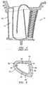
- FIG. 1 where there is shown an airfoil portion 10 of a turbine engine component 12. As can be seen from the figure, a radial flow leading edge cavity 14 is used to effect cooling of the leading edge region.
- FIG. 2 illustrates the leading edge 30 of an airfoil portion 32 of a turbine engine component.
- the leading edge 30 has a leading edge cavity 34 in which a cooling fluid, such as engine bleed air, flows in a radial direction.
- the leading edge 30 also has a nose portion 36 and an external stagnation region 38.
- trip strips are desirable to provide adequate cooling of the leading edge 30, especially at the nose portion 36 of the airfoil portion 32 adjacent to the external stagnation region 38.
- the trip strip arrangement which will be discussed hereinafter provides high heat transfer to the leading edge 30 of the airfoil portion 32.
- a plurality of trip strips 40 are positioned on the pressure side 42 of the airfoil portion 32, while a plurality of trip strips 44 are placed on the suction side 46 of the airfoil portion 32.
- the parallel trip strips 40 and the parallel trip strips 44 each extend in a direction 48 of flow in the leading edge cavity 34.
- the leading edges of the trip strips 40 and 44 are separated by a gap 45.
- the gap 45 is maintained at a distance up to five times the height of the trip strips 40 or 44.
- the gap 45 may be located on a parting line of the airfoil portion 32.
- the trip strips 40 on the pressure side 42 meet the trip strips 44 on the suction side 46 at the leading edge nose portion 36 and create a chevron shape as shown schematically in FIG. 5 .
- the orientation of the trip strips 40 and 44 in the cavity 34 also increases heat transfer at the leading edge of the airfoil portion 32.
- the trip strips 40 and 44 may be oriented at an angle ⁇ of approximately 45 degrees relative to an engine centerline 52.
- the leading edges 54 and 56 of the trip strips 40 and 44 are positioned in the region of highest heat load, in this case the leading edge nose 36.
- This trip strip orientation permits the creation of the turbulent vortex 49 in the cavity 34.
- the flow initially hits the leading edge of the trip strip and separates from the airfoil surface. The flow then re-attaches downstream of the trip strip leading edge and moves toward the divider rib 60 between the leading edge cavity 34 and the adjacent cavity 62.
- trip strip configuration allows for cooling flow to impinge on the leading edge nose 36, further enhancing heat transfer.
- the leading edges of the trip strips 40 and 44 are located at the nose 36 of the leading edge cavity 34.
- the trip strip configuration of the present invention may maintain a P/E ratio between 3.0 and 25 where P is the radial pitch (distance) between adjacent trip strips and E is trip strip height. Further, the trip strip configuration according to the invention maintains an E/H ratio of between 0.15 and 1.50 where E is trip strip height and H is the height of the cavity 34.
Landscapes
- Engineering & Computer Science (AREA)
- Mechanical Engineering (AREA)
- General Engineering & Computer Science (AREA)
- Turbine Rotor Nozzle Sealing (AREA)
Claims (5)
- Composant de moteur à turbine comportant :une partie (32) de profil aérodynamique présentant un bord d'attaque (30), un extrados (46) et un intrados (42) ;une cavité (34) de bord d'attaque à écoulement radial à travers laquelle circule un fluide de refroidissement servant à refroidir ledit bord d'attaque (30) ; et comportant en outre :un moyen servant à générer un tourbillon dans ladite cavité (34) de bord d'attaque qui frappe une partie (36) de nez de ladite cavité (34) de bord d'attaque, ledit moyen de génération de tourbillon comportant un premier ensemble de bandes (40) de déclenchement et un deuxième ensemble de bandes (44) de déclenchement dont les bords d'attaque (54 ; 56) respectifs sont situés au niveau de la partie (36) de nez du bord d'attaque ;ledit premier ensemble de bandes (40) de déclenchement comportant une pluralité de bandes de déclenchement parallèles s'étendant dans une direction d'écoulement (48) dans ladite cavité (34) de bord d'attaque ;ledit deuxième ensemble de bandes (44) de déclenchement comportant une pluralité de bandes de déclenchement parallèles s'étendant dans une direction d'écoulement (48) dans ladite cavité (34) de bord d'attaque ;et chacune desdites bandes (40 ; 44) de déclenchement présentant un rapport E/H compris entre 0,15 et 1,50 où E est la hauteur des bandes de déclenchement et H est la hauteur de la cavité (34) ;caractérisé en ce que les bords d'attaque (54) respectifs desdites premières bandes (40) de déclenchement sont opposés aux bords d'attaque (56) respectifs desdites deuxièmes bandes (44) de déclenchement dans la direction contournant le bord d'attaque de la partie (32) de profil aérodynamique et sont séparés de ceux-ci par une pluralité d'interstices (45) dans la direction contournant le bord d'attaque (30) de la partie (32) de profil aérodynamique ;chacun desdits interstices (45) étant maintenu à une distance allant jusqu'à cinq fois la hauteur de chacune desdites bandes (40 ; 44) de déclenchement.
- Composant de moteur à turbine selon la revendication 1, ladite pluralité d'interstices (45) étant située le long d'une ligne de division de ladite partie (32) de profil aérodynamique.
- Composant de moteur à turbine selon la revendication 1 ou 2, chacune desdites bandes (40 ; 44) de déclenchement étant orientée suivant un angle de 45 degrés par rapport à un axe de symétrie d'un moteur dont le composant fait partie.
- Composant de moteur à turbine selon l'une quelconque des revendications précédentes, ledit bord d'attaque (54 ; 56) de chacune desdites bandes (40 ; 44) de déclenchement étant positionné dans une région de charge thermique la plus élevée.
- Composant de moteur à turbine selon l'une quelconque des revendications précédentes, chacune desdites bandes (40 ; 44) de déclenchement présentant un rapport E/H situé dans l'intervalle allant de 3,0 à 25, où P est un pas radial entre des bandes (40 ; 44) de déclenchement adjacentes et E est la hauteur des bandes de déclenchement.
Applications Claiming Priority (1)
| Application Number | Priority Date | Filing Date | Title |
|---|---|---|---|
| US11/473,894 US8690538B2 (en) | 2006-06-22 | 2006-06-22 | Leading edge cooling using chevron trip strips |
Publications (3)
| Publication Number | Publication Date |
|---|---|
| EP1873354A2 EP1873354A2 (fr) | 2008-01-02 |
| EP1873354A3 EP1873354A3 (fr) | 2010-12-22 |
| EP1873354B1 true EP1873354B1 (fr) | 2013-03-13 |
Family
ID=38461941
Family Applications (1)
| Application Number | Title | Priority Date | Filing Date |
|---|---|---|---|
| EP07252554A Active EP1873354B1 (fr) | 2006-06-22 | 2007-06-22 | Refroidissement du bord d'attaque utilisant des bandes à chevrons |
Country Status (3)
| Country | Link |
|---|---|
| US (1) | US8690538B2 (fr) |
| EP (1) | EP1873354B1 (fr) |
| JP (1) | JP2008002465A (fr) |
Families Citing this family (31)
| Publication number | Priority date | Publication date | Assignee | Title |
|---|---|---|---|---|
| US20070297916A1 (en) * | 2006-06-22 | 2007-12-27 | United Technologies Corporation | Leading edge cooling using wrapped staggered-chevron trip strips |
| EP1921269A1 (fr) * | 2006-11-09 | 2008-05-14 | Siemens Aktiengesellschaft | Aube de turbine |
| US8376706B2 (en) * | 2007-09-28 | 2013-02-19 | General Electric Company | Turbine airfoil concave cooling passage using dual-swirl flow mechanism and method |
| US8128366B2 (en) * | 2008-06-06 | 2012-03-06 | United Technologies Corporation | Counter-vortex film cooling hole design |
| GB0909255D0 (en) | 2009-06-01 | 2009-07-15 | Rolls Royce Plc | Cooling arrangements |
| US9995148B2 (en) | 2012-10-04 | 2018-06-12 | General Electric Company | Method and apparatus for cooling gas turbine and rotor blades |
| US9850762B2 (en) | 2013-03-13 | 2017-12-26 | General Electric Company | Dust mitigation for turbine blade tip turns |
| EP3047102B1 (fr) | 2013-09-16 | 2020-05-06 | United Technologies Corporation | Turbine à gaz dotée d'un disque dont la périphérie est pourvue de saillies |
| WO2016025054A2 (fr) | 2014-05-29 | 2016-02-18 | General Electric Company | Éléments de turbine à gaz ayant des caractéristiques de refroidissement |
| US9957816B2 (en) | 2014-05-29 | 2018-05-01 | General Electric Company | Angled impingement insert |
| US10422235B2 (en) | 2014-05-29 | 2019-09-24 | General Electric Company | Angled impingement inserts with cooling features |
| US10563514B2 (en) | 2014-05-29 | 2020-02-18 | General Electric Company | Fastback turbulator |
| US10364684B2 (en) | 2014-05-29 | 2019-07-30 | General Electric Company | Fastback vorticor pin |
| US10119404B2 (en) | 2014-10-15 | 2018-11-06 | Honeywell International Inc. | Gas turbine engines with improved leading edge airfoil cooling |
| US10233775B2 (en) | 2014-10-31 | 2019-03-19 | General Electric Company | Engine component for a gas turbine engine |
| US10280785B2 (en) | 2014-10-31 | 2019-05-07 | General Electric Company | Shroud assembly for a turbine engine |
| US10577947B2 (en) | 2015-12-07 | 2020-03-03 | United Technologies Corporation | Baffle insert for a gas turbine engine component |
| US10280841B2 (en) | 2015-12-07 | 2019-05-07 | United Technologies Corporation | Baffle insert for a gas turbine engine component and method of cooling |
| US10337334B2 (en) * | 2015-12-07 | 2019-07-02 | United Technologies Corporation | Gas turbine engine component with a baffle insert |
| US10422233B2 (en) | 2015-12-07 | 2019-09-24 | United Technologies Corporation | Baffle insert for a gas turbine engine component and component with baffle insert |
| US10830051B2 (en) * | 2015-12-11 | 2020-11-10 | General Electric Company | Engine component with film cooling |
| US10352177B2 (en) | 2016-02-16 | 2019-07-16 | General Electric Company | Airfoil having impingement openings |
| US10519779B2 (en) * | 2016-03-16 | 2019-12-31 | General Electric Company | Radial CMC wall thickness variation for stress response |
| US10208604B2 (en) * | 2016-04-27 | 2019-02-19 | United Technologies Corporation | Cooling features with three dimensional chevron geometry |
| US10830060B2 (en) * | 2016-12-02 | 2020-11-10 | General Electric Company | Engine component with flow enhancer |
| US10590778B2 (en) | 2017-08-03 | 2020-03-17 | General Electric Company | Engine component with non-uniform chevron pins |
| US10577944B2 (en) | 2017-08-03 | 2020-03-03 | General Electric Company | Engine component with hollow turbulators |
| US20200240275A1 (en) * | 2019-01-30 | 2020-07-30 | United Technologies Corporation | Gas turbine engine components having interlaced trip strip arrays |
| US11788416B2 (en) * | 2019-01-30 | 2023-10-17 | Rtx Corporation | Gas turbine engine components having interlaced trip strip arrays |
| CN110700893A (zh) * | 2019-10-14 | 2020-01-17 | 哈尔滨工程大学 | 一种包括v肋-凹坑复合冷却结构的燃气轮机涡轮叶片 |
| CN114526125B (zh) * | 2022-04-24 | 2022-07-26 | 中国航发四川燃气涡轮研究院 | 一种囊袋旋腔冷却单元及涡轮叶片结构 |
Family Cites Families (20)
| Publication number | Priority date | Publication date | Assignee | Title |
|---|---|---|---|---|
| US4257737A (en) * | 1978-07-10 | 1981-03-24 | United Technologies Corporation | Cooled rotor blade |
| US4775296A (en) * | 1981-12-28 | 1988-10-04 | United Technologies Corporation | Coolable airfoil for a rotary machine |
| US4514144A (en) * | 1983-06-20 | 1985-04-30 | General Electric Company | Angled turbulence promoter |
| US5232343A (en) * | 1984-05-24 | 1993-08-03 | General Electric Company | Turbine blade |
| US5052889A (en) * | 1990-05-17 | 1991-10-01 | Pratt & Whintey Canada | Offset ribs for heat transfer surface |
| US5246340A (en) * | 1991-11-19 | 1993-09-21 | Allied-Signal Inc. | Internally cooled airfoil |
| US5700132A (en) * | 1991-12-17 | 1997-12-23 | General Electric Company | Turbine blade having opposing wall turbulators |
| US5681144A (en) * | 1991-12-17 | 1997-10-28 | General Electric Company | Turbine blade having offset turbulators |
| US5695321A (en) * | 1991-12-17 | 1997-12-09 | General Electric Company | Turbine blade having variable configuration turbulators |
| JP3268070B2 (ja) * | 1993-06-29 | 2002-03-25 | 三菱重工業株式会社 | ガスタービンの中空冷却動翼 |
| US5431537A (en) * | 1994-04-19 | 1995-07-11 | United Technologies Corporation | Cooled gas turbine blade |
| JPH08338202A (ja) * | 1995-06-09 | 1996-12-24 | Hitachi Ltd | ガスタービン動翼 |
| JPH10280905A (ja) * | 1997-04-02 | 1998-10-20 | Mitsubishi Heavy Ind Ltd | ガスタービン冷却翼のタービュレータ |
| JPH1122489A (ja) * | 1997-07-04 | 1999-01-26 | Toshiba Corp | タービン冷却翼 |
| EP0892149B1 (fr) | 1997-07-14 | 2003-01-22 | ALSTOM (Switzerland) Ltd | Système de refroidissement pour le bord d'attac d'une aube creuse pour turbine à gaz |
| US6406260B1 (en) * | 1999-10-22 | 2002-06-18 | Pratt & Whitney Canada Corp. | Heat transfer promotion structure for internally convectively cooled airfoils |
| GB0222352D0 (en) * | 2002-09-26 | 2002-11-06 | Dorling Kevin | Turbine blade turbulator cooling design |
| US6884036B2 (en) * | 2003-04-15 | 2005-04-26 | General Electric Company | Complementary cooled turbine nozzle |
| FR2858352B1 (fr) * | 2003-08-01 | 2006-01-20 | Snecma Moteurs | Circuit de refroidissement pour aube de turbine |
| US20070297916A1 (en) * | 2006-06-22 | 2007-12-27 | United Technologies Corporation | Leading edge cooling using wrapped staggered-chevron trip strips |
-
2006
- 2006-06-22 US US11/473,894 patent/US8690538B2/en active Active
-
2007
- 2007-06-19 JP JP2007160905A patent/JP2008002465A/ja active Pending
- 2007-06-22 EP EP07252554A patent/EP1873354B1/fr active Active
Also Published As
| Publication number | Publication date |
|---|---|
| EP1873354A2 (fr) | 2008-01-02 |
| EP1873354A3 (fr) | 2010-12-22 |
| US8690538B2 (en) | 2014-04-08 |
| JP2008002465A (ja) | 2008-01-10 |
| US20070297917A1 (en) | 2007-12-27 |
Similar Documents
| Publication | Publication Date | Title |
|---|---|---|
| US8690538B2 (en) | Leading edge cooling using chevron trip strips | |
| EP1870561B1 (fr) | Refroidissement du bord d'attaque d'un composant de turbine à gaz par générateurs de turbulence | |
| EP2131108B1 (fr) | Conception d'un trou de refroidissement à film à vortex inversé | |
| US8066484B1 (en) | Film cooling hole for a turbine airfoil | |
| JP4063937B2 (ja) | ガスタービンエンジン内の翼の冷却通路の乱流促進構造 | |
| US8066485B1 (en) | Turbine blade with tip section cooling | |
| US8011888B1 (en) | Turbine blade with serpentine cooling | |
| US8435004B1 (en) | Turbine blade with tip rail cooling | |
| US8777569B1 (en) | Turbine vane with impingement cooling insert | |
| US8182221B1 (en) | Turbine blade with tip sealing and cooling | |
| US4515526A (en) | Coolable airfoil for a rotary machine | |
| KR101434926B1 (ko) | 터빈 블레이드, 및 엔진 부품 | |
| US8562295B1 (en) | Three piece bonded thin wall cooled blade | |
| US8801377B1 (en) | Turbine blade with tip cooling and sealing | |
| US8398370B1 (en) | Turbine blade with multi-impingement cooling | |
| US7955053B1 (en) | Turbine blade with serpentine cooling circuit | |
| US8221055B1 (en) | Turbine stator vane with endwall cooling | |
| US7690894B1 (en) | Ceramic core assembly for serpentine flow circuit in a turbine blade | |
| EP0852285A1 (fr) | Turbulateurs pour les passages de réfroidissement des aubes rotoriques d'une turbine à gas | |
| US7637720B1 (en) | Turbulator for a turbine airfoil cooling passage | |
| JP4929097B2 (ja) | ガスタービン翼 | |
| EP2876258B1 (fr) | Aube de turbine à gaz | |
| EP3696377B1 (fr) | Composant de moteur à turbine à gaz comprenant un refroidissement de bord de fuite par impact incliné sur une surface améliorée avec des agencements de chevron coulés | |
| US20180230815A1 (en) | Turbine airfoil with thin trailing edge cooling circuit | |
| US8491263B1 (en) | Turbine blade with cooling and sealing |
Legal Events
| Date | Code | Title | Description |
|---|---|---|---|
| PUAI | Public reference made under article 153(3) epc to a published international application that has entered the european phase |
Free format text: ORIGINAL CODE: 0009012 |
|
| AK | Designated contracting states |
Kind code of ref document: A2 Designated state(s): AT BE BG CH CY CZ DE DK EE ES FI FR GB GR HU IE IS IT LI LT LU LV MC MT NL PL PT RO SE SI SK TR |
|
| AX | Request for extension of the european patent |
Extension state: AL BA HR MK YU |
|
| PUAL | Search report despatched |
Free format text: ORIGINAL CODE: 0009013 |
|
| AK | Designated contracting states |
Kind code of ref document: A3 Designated state(s): AT BE BG CH CY CZ DE DK EE ES FI FR GB GR HU IE IS IT LI LT LU LV MC MT NL PL PT RO SE SI SK TR |
|
| AX | Request for extension of the european patent |
Extension state: AL BA HR MK RS |
|
| 17P | Request for examination filed |
Effective date: 20110621 |
|
| AKX | Designation fees paid |
Designated state(s): DE GB |
|
| GRAP | Despatch of communication of intention to grant a patent |
Free format text: ORIGINAL CODE: EPIDOSNIGR1 |
|
| GRAS | Grant fee paid |
Free format text: ORIGINAL CODE: EPIDOSNIGR3 |
|
| GRAA | (expected) grant |
Free format text: ORIGINAL CODE: 0009210 |
|
| AK | Designated contracting states |
Kind code of ref document: B1 Designated state(s): DE GB |
|
| REG | Reference to a national code |
Ref country code: GB Ref legal event code: FG4D |
|
| REG | Reference to a national code |
Ref country code: DE Ref legal event code: R096 Ref document number: 602007029010 Country of ref document: DE Effective date: 20130508 |
|
| PLBE | No opposition filed within time limit |
Free format text: ORIGINAL CODE: 0009261 |
|
| STAA | Information on the status of an ep patent application or granted ep patent |
Free format text: STATUS: NO OPPOSITION FILED WITHIN TIME LIMIT |
|
| 26N | No opposition filed |
Effective date: 20131216 |
|
| REG | Reference to a national code |
Ref country code: DE Ref legal event code: R097 Ref document number: 602007029010 Country of ref document: DE Effective date: 20131216 |
|
| REG | Reference to a national code |
Ref country code: DE Ref legal event code: R082 Ref document number: 602007029010 Country of ref document: DE Representative=s name: SCHMITT-NILSON SCHRAUD WAIBEL WOHLFROM PATENTA, DE |
|
| REG | Reference to a national code |
Ref country code: DE Ref legal event code: R082 Ref document number: 602007029010 Country of ref document: DE Representative=s name: SCHMITT-NILSON SCHRAUD WAIBEL WOHLFROM PATENTA, DE Ref country code: DE Ref legal event code: R081 Ref document number: 602007029010 Country of ref document: DE Owner name: UNITED TECHNOLOGIES CORP. (N.D.GES.D. STAATES , US Free format text: FORMER OWNER: UNITED TECHNOLOGIES CORPORATION, HARTFORD, CONN., US |
|
| REG | Reference to a national code |
Ref country code: DE Ref legal event code: R081 Ref document number: 602007029010 Country of ref document: DE Owner name: RAYTHEON TECHNOLOGIES CORPORATION (N.D.GES.D.S, US Free format text: FORMER OWNER: UNITED TECHNOLOGIES CORP. (N.D.GES.D. STAATES DELAWARE), FARMINGTON, CONN., US Ref country code: DE Ref legal event code: R081 Ref document number: 602007029010 Country of ref document: DE Owner name: RTX CORPORATION (N.D.GES.D. STAATES DELAWARE),, US Free format text: FORMER OWNER: UNITED TECHNOLOGIES CORP. (N.D.GES.D. STAATES DELAWARE), FARMINGTON, CONN., US |
|
| P01 | Opt-out of the competence of the unified patent court (upc) registered |
Effective date: 20230519 |
|
| PGFP | Annual fee paid to national office [announced via postgrant information from national office to epo] |
Ref country code: DE Payment date: 20250520 Year of fee payment: 19 |
|
| PGFP | Annual fee paid to national office [announced via postgrant information from national office to epo] |
Ref country code: GB Payment date: 20250520 Year of fee payment: 19 |
|
| REG | Reference to a national code |
Ref country code: DE Ref legal event code: R081 Ref document number: 602007029010 Country of ref document: DE Owner name: RTX CORPORATION (N.D.GES.D. STAATES DELAWARE),, US Free format text: FORMER OWNER: RAYTHEON TECHNOLOGIES CORPORATION (N.D.GES.D.STAATES DELAWARE), ARLINGTON, VA, US |