EP1873375A2 - Kühlsystem für einen Verdichter einer Gasturbine - Google Patents
Kühlsystem für einen Verdichter einer Gasturbine Download PDFInfo
- Publication number
- EP1873375A2 EP1873375A2 EP07012501A EP07012501A EP1873375A2 EP 1873375 A2 EP1873375 A2 EP 1873375A2 EP 07012501 A EP07012501 A EP 07012501A EP 07012501 A EP07012501 A EP 07012501A EP 1873375 A2 EP1873375 A2 EP 1873375A2
- Authority
- EP
- European Patent Office
- Prior art keywords
- gas
- liquid
- compressor
- compressed
- water
- Prior art date
- Legal status (The legal status is an assumption and is not a legal conclusion. Google has not performed a legal analysis and makes no representation as to the accuracy of the status listed.)
- Withdrawn
Links
Images






Classifications
-
- F—MECHANICAL ENGINEERING; LIGHTING; HEATING; WEAPONS; BLASTING
- F02—COMBUSTION ENGINES; HOT-GAS OR COMBUSTION-PRODUCT ENGINE PLANTS
- F02C—GAS-TURBINE PLANTS; AIR INTAKES FOR JET-PROPULSION PLANTS; CONTROLLING FUEL SUPPLY IN AIR-BREATHING JET-PROPULSION PLANTS
- F02C7/00—Features, components parts, details or accessories, not provided for in, or of interest apart form groups F02C1/00 - F02C6/00; Air intakes for jet-propulsion plants
- F02C7/12—Cooling of plants
- F02C7/14—Cooling of plants of fluids in the plant, e.g. lubricant or fuel
- F02C7/141—Cooling of plants of fluids in the plant, e.g. lubricant or fuel of working fluid
- F02C7/143—Cooling of plants of fluids in the plant, e.g. lubricant or fuel of working fluid before or between the compressor stages
- F02C7/1435—Cooling of plants of fluids in the plant, e.g. lubricant or fuel of working fluid before or between the compressor stages by water injection
-
- F—MECHANICAL ENGINEERING; LIGHTING; HEATING; WEAPONS; BLASTING
- F04—POSITIVE - DISPLACEMENT MACHINES FOR LIQUIDS; PUMPS FOR LIQUIDS OR ELASTIC FLUIDS
- F04D—NON-POSITIVE-DISPLACEMENT PUMPS
- F04D29/00—Details, component parts, or accessories
- F04D29/58—Cooling; Heating; Diminishing heat transfer
- F04D29/582—Cooling; Heating; Diminishing heat transfer specially adapted for elastic fluid pumps
- F04D29/5846—Cooling; Heating; Diminishing heat transfer specially adapted for elastic fluid pumps cooling by injection
Definitions
- the present invention relates to a cooling apparatus adapted to cool compressed fluid from a gas compressor which compresses air, steam, etc., a gas turbine system using a cooling apparatus, a heat pump system using a cooling apparatus, a cooling method, and a method for operating a cooling apparatus.
- JP-A-2005-274070 discloses an apparatus which injects desuperheated water into superheated steam to desuperheat the steam close to a saturation temperature.
- a cooling apparatus as an intercooling system according to the present invention, which is located between a plurality of compression stages of a gas compressor to cool a gas compressed in the above-mentioned compressor, the apparatus comprising means for cooling the abovementioned compressed gas by sprinkling a desired amount or more of liquid while restraining inflow of the liquid into the above-mentioned compression stages.
- a technique used for improving the compression efficiency of a compressor will be explained below.
- intercooling of a compressed gas is performed to increase the density of the gas to reduce the power necessary for compression, thus improving the compression efficiency.
- water is sprinkled into the gas sucked in the compressor to cool the compressed gas, and the sprinkled water is evaporated by the heat of the compressed gas and an effect of temperature rise within the compressor, thus increasing the flow rate of the compressed gas, which is a mainstream fluid of the compressor, while reducing the compression power.
- the flow rate of the compressed gas can be increased while reducing the compression power of the compressor.
- Increasing the flow rate of the gas in the intercooler means that more amount of gas has been compressed by the same compression power, resulting in improved compression efficiency.
- the compression efficiency of the compressor is improved thanks to two different effects: one is an effect of cooling the compressed gas and the other is an effect of increased amount of the compressed gas through evaporation of sprinkled water.
- the compression efficiency is maximized when the gas is cooled to the saturation temperature. Therefore, in order to improve the compression efficiency, it is desirable to sprinkle such a large amount of water that can cool the compressed gas to the saturation temperature.
- the temperature of the compressed gas for example, at the intercooler outlet as a reference.
- the mainstream pressure of the compressor is an approximately constant value and, if the pressure is constant, the saturation temperature at the relevant pressure will be accordingly determined. If the temperature of the compressed gas at the intercooler outlet is set up to 5 to 10°C higher than the saturation temperature, the compressed gas is superheated at the intercooler outlet and therefore there is little possibility that the sprinkled water has not evaporated and flows into the compressor as a liquid.
- the temperature of the compressed gas is set up to 5 to 10°C higher than the saturation temperature because it is necessary to take a margin in consideration of a measurement error of gas temperature as well as a time difference from the start of measurement to completion of adjustment of the amount of water distribution. It is necessary to take this margin so that the temperature of the compressed gas becomes high. If the temperature of the compressed gas becomes lower than the saturation temperature at the intercooler outlet, the compressed gas here has been saturated and therefore part of the sprinkled water has not completely evaporated or remains liquid, resulting in degraded reliability of the compressor.
- a technique based on a measurement value other than the temperature at the intercooler outlet can also be considered.
- an intercooler of embodiments of the present invention is not based on control of the amount of water distribution but configured so that the compressed gas be cooled down to the saturation temperature while structurally restraining the degradation of the reliability of the compressor.
- the intercooler is provided with means for restraining inflow of sprinkled water into the compressor, and configured so that the compressed gas be cooled with a desired amount or more of water distribution.
- the desired amount of water means such an amount of water that can cool the temperature of the compressed gas at the intercooler outlet to the saturation temperature.
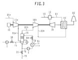
- FIG. 3 illustrates a recuperated-cycle gas turbine system having an intercooling system of a compressor according to an embodiment of the present invention.
- the recuperated-cycle gas turbine system mainly includes compressors 10a and 10b which compress air, a recuperator 60 which heats compressed air obtained by compressing air with the compressor 10b using exhaust gas of a gas turbine, a combustor 12 which combusts air heated by the recuperator 60 and fuel 50 to generate combustion gas, a turbine 14 which is driven by the above-mentioned combustion gas generated by the combustor 12, and a stack 82 which discharges combustion gas as exhaust gas, the combustion gas being produced by driving the turbine 14 and performing heat exchange with compressed air by the recuperator 60.
- the present embodiment assumes that the pressure ratio of the gas turbine is 16, the pressure ratio of the compressors 10a and 10b is respectively 4, and the inlet flow rate of the gas turbine is 10 kg/s. Furthermore, the present embodiment assumes that the temperature efficiency of the recuperator is 90% and the polytropic efficiency of the compressors and the turbine is 88%.
- the motive energy obtained from an output shaft of the gas turbine is transformed into electric power by a dynamo 16 and then connected to the transmission grid.
- a characteristic component according to the present embodiment is the cooling tower 36 which is an intercooling system provided to a discharge pipe 86 of the compressor 10a.
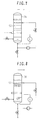
- the cooling tower 36 will be explained in detail below with reference to Fig. 2.
- Fig. 2 is a detailed diagram showing the cooling tower 36.
- a cooling tower 36a shown in Fig. 2 is provided to a circulating pump 6 which recirculates circulating water dropped to the bottom of the tower to an upper part of packing 71 in the tower. Furthermore, makeup water can be supplied to a reservoir 74 by a feed pump 7 and a regulating valve 38.
- a gas distributor 70 which compressed air enters is provided to distribute the compressed air led from the compressor 10a through a discharge pipe 86a so that the air may not concentrate at a certain portion in the cooling tower 36a. This gas distributor 70 is provided with a downward opening in order to avoid inflow of droplets dropping from above.
- the cooling tower 36 shown in Fig. 2 is a packed tower using the packing 71.
- the packing 71 is provided in order to increase the effective area of gas-liquid contact above the gas distributor 70.
- As the packing 71 a structure having a large surface area per unit volume is used, which is generally used in chemical plants for example.
- random packing commercially available is used as the packing 71.
- a cooling tower 36a having a tower diameter of 1.8 m is applied based on flooding characteristics generally disclosed as performance specifications of the packing 71.
- Flooding refers to a phenomenon in which, when the flow velocity of gas increases in a packed tower or perforated plate tower for letting a liquid film flow down against an upward gas flow, sprinkled water cannot flow downward because of upward force exerted from the gas flow.
- the embodiment applies the packing 71 with a packing height of 0.8 m assuming that, when water with a temperature of about 35°C is sprinkled, the air temperature at the outlet of the cooling tower 36a becomes around 60°C.
- a demister 72 which is a liquid passage restrainer for restraining inflow of liquid into the compressor removes droplets, such as entrainment produced by shearing force between upward air flow on the surface of the packing 71 and downward liquid film flow, to restrain inflow of droplets into the compressor 10b located downstream. For this reason, it is desirable to locate the demister 72 above the packing 71 and the liquid distributor 80.
- the circulating pump 6 sucks in liquidus water from the reservoir 74 at the bottom of the cooling tower 36a through a pipe 76.
- a heat exchanger 90 performs heat exchange between discharge water of the circulating pump 6 and low-temperature cooling water 91.
- the circulating water cooled by the heat exchanger 90 is supplied through the liquid distributor 80 located above the packing to the cooling tower 36a.
- the liquid distributor 80 generally used in chemical plants, etc., is provided with a function for distributing liquidus water as evenly as possible to the entire area of the packing.
- a water gauge 78 is provided to the cooling tower 36a. If the water level of the reservoir 74 drops, the regulating valve 38 on a pipe 75 is operated to supply makeup water from a water source. If the water level of the reservoir 74 rises, a regulating valve 39 on a pipe 79 is operated to discharge liquidus water out of the system.
- Figs. 5A to 5C are graphs respectively showing distributions of temperature, absolute humidity, and amount of humidification in terms of heightwise positions at the location of packing 71 in the cooling tower 36 of the present embodiment.
- air indicated with a solid line
- a liquid film dotted line
- a gas-liquid interface between the liquid film and the air is covered by humid air having saturated steam pressure corresponding to the temperature of the liquid film.
- the absolute humidity (indicated with a dotted line) of humid air on the liquid film surface is higher than the absolute humidity (solid line) of the mainstream humid air at the lower part of the packing 71. Therefore, as shown in Fig. 5C, steam transfers into the mainstream air from the liquid film surface because a difference in the steam pressure acts as motive force. As a result, the absolute humidity of the mainstream air rises as it flows upward. At the upper part of the packing 71, however, this relationship is interchanged because of low temperature of liquid film water; as a result, the absolute humidity of the mainstream air rises and accordingly moisture in the mainstream air condenses and transfers toward the liquid film.
- the amount of humidification from the low-temperature water to the compressed air is comparatively small, i.e., about 0.6 % by mass of air.
- the air temperature at the outlet of the cooling tower is cooled down to about 62°C, which means that the mainstream air has been cooled by more than 100°C in the cooling tower 36.
- Liquid film water dropped from the packing 71 flows down into the reservoir 74 in the cooling tower 36.
- Moisture lost by evaporation is replenished into the reservoir 74 through the feed pump 7 and the regulating valve 38.
- Hot water with a temperature of about 55°C is supplied from the reservoir 74 to the heat exchanger 90 by the circulating pump 6.
- hot water with a temperature of about 55°C is cooled down to about 35°C through heat exchange with the low-temperature cooling water 91 and then supplied again to the cooling tower 36.
- the compressed air cooled down to about 62°C by the cooling tower 36 is sucked in through an inlet pipe 85b to the compressor 10b and then compressed to 1600kPa.
- the temperature at this time becomes about 240°C.
- the inlet air temperature and discharge temperature of the compressor 10b are comparatively low (about 62°C and about 240°C, respectively), the compression power can remarkably be reduced in comparison with a case when these temperatures are high.
- Table 1 indicates comparison of compression power between a case when an intercooling system is prepared and a case when it is not, with a virtual compressor having a pressure ratio of 16 consisting of two compressors having a pressure ratio of 4 connected in series, shown in the present embodiment. It is clear that, when the mainstream air has been cooled down to about 62°C by the intercooling system, the compression power can be reduced by about 17%.
- Table 1 Intercooling system Required compression power [kW] (With an inlet flow rate of 10 kg/s) Compressor 10a Compressor 10b Total Without cooling tower 1600 2500 4100 With cooling tower (up to about 62°C) 1600 1900 3500
- the compressed air with a temperature of about 240°C in a discharge pipe 86b flows into a heated fluid path of the recuperator 60, and performs heat exchange with exhaust gas with a temperature of about 560°C in the turbine 14 to be heated to about 530°C.
- This compressed air is supplied through a heated fluid outlet pipe 61 of the recuperator 60 to the combustor 12, and is combusted with fuel 50 to become combustion gas with a temperature of about 1300°C. Since the compressed air to be supplied to the combustor 12 has been heated by the recuperator 60, it is possible to remarkably save the flow rate of the fuel 50 required at this time in comparison with a case when the recuperator 60 is not used, resulting in improved plant thermal efficiency.
- liquid water before distribution in the cooling tower 36 is cooled by the heat exchanger 90.
- the heat exchanger 90 performs heat exchange between liquids, the overall thermal conductivity thereof is larger than that of a heat exchanger which performs heat exchange between gas and liquid, providing an advantage that the heat exchanger can be configured compactly.
- the temperature of water flowing in the heat exchanger 90 is about 55°C at maximum, high corrosion resistance is not required. Therefore, a comparatively inexpensive heat exchanger, such as a plate type heat exchanger, can be used as the heat exchanger 90.
- the present embodiment utilizes the liquid water of the reservoir 74 as sprinkling water from the liquid distributor 80 by circulating the liquid water of the reservoir 74 using the circulating pump 6.
- the sprinkled water water that has not completely evaporated or remains liquid after heat exchange with the mainstream air flows down into the reservoir 74.
- a pressure vessel, the packing 71, etc. of the cooling tower 36 are mass-production products which are comparatively inexpensive and generally used in chemical plants. Furthermore, of circulating water circulating from the cooling tower 36 through the heat exchanger 90, part of the liquid film surface evaporates. Impurities are condensed to circulating water. In order to restrain water quality deterioration of the reservoir 74 caused by the condensing of impurities contained in makeup water, it is desirable to operate the regulating valve 39 to discharge part of the liquidus water continuously or intermittently out of the system.
- Fig. 1 shows a simple-cycle gas turbine which applies the intercooling system according to the present embodiment. So far, an example which applies an intercooling system to the recuperated-cycle gas turbine has been explained with reference to Fig. 3. However, as shown in Fig. 1, it may be possible to apply the intercooling system according to the present embodiment to a simple-cycle gas turbine. Application of the intercooling system to a simple-cycle or recuperated-cycle gas turbine is advantageous in that the compression power can be reduced as mentioned above. Furthermore, by cooling compressed air, this case also provides an effect of preventing components of compressor from being heated to high temperature to prolong the operating life. When using bleed air from compressor to cool hot components of the turbine, the temperature of cooling air used to cool components of the turbine can be decreased by performing intercooling of the compressor, thus saving the amount of cooling air.
- the recuperated-cycle gas turbine since the discharge temperature of the compressor 10b also decreases because of intercooling effect, can provide an effect of increasing the amount of exhaust heat which can be recovered from exhaust gas by the recuperator 60. Specifically, in terms of the power generation efficiency, a case when the intercooling system according to the present embodiment is applied to the recuperated-cycle gas turbine shown in Fig. 3 can obtain higher effect than a case when it is applied to a simple-cycle gas turbine.
- Fig. 7 is a detailed diagram showing the cooling tower 36.
- the cooling tower 36b shown in Fig. 7 is a perforated plate tower using a perforated plate 92 instead of the packing 71 used in the cooling tower 36a shown in Fig. 2.
- the use of the perforated plate 92 for the cooling tower 36 is characterized by favorable geometric flow rate distribution of the gas and liquid in the tower and higher immunity to contamination in comparison with a packed tower.
- the packed tower is more advantageous than the perforated plate tower in higher contact efficiency per unit volume and lower pressure loss.
- Fig. 8 is a detailed diagram showing the cooling tower 36.
- the cooling tower 36c shown in Fig. 8 is a spray tower in which large volume of droplets are sprinkled (or sprayed) from a spray nozzle 93 instead of installing the packing 71 in the cooling tower 36a shown in Fig. 2.
- the spray tower is more advantageous than the packed tower and the perforated plate tower in lower pressure loss.
- the predetermined size means such a size with which water has not completely evaporate for each droplet, i.e., some droplets have not completely evaporated or remain liquid and flow down into the reservoir 74.
- a packed tower which is the cooling tower 36a shown in Fig. 2 is used as an intercooling system of the compressor, it may be possible to use the perforated plate tower shown in Fig. 7 or the spray tower shown in Fig. 8 instead of the packed tower. What is necessary is to increase the contact area of the mainstream air and droplets. By increasing the gas-liquid contact area, the efficiency of heat exchange can be improved and efficient evaporation of droplets promoted, resulting in reduced size and cost of the cooling tower 36. The cooling efficiency of the cooling tower 36 can further be improved.
- the predetermined water level refers to a design water level uniquely determined for each system, i.e., a water level that can secure such an amount of water that does not cause shortage of circulating water at least during operation of the cooling tower. Then, the water in the reservoir 74 in the cooling tower 36 is supplied to the heat exchanger 90 by means of the circulating pump 6.
- the water that has been heat-exchanged with the low-temperature cooling water 91 by the heat exchanger 90 is supplied to the liquid distributor 80 of the cooling tower 36 through the regulating valve 84.
- the water sprinkled on the surface of the packing 71 from the liquid distributor 80 flows down into the reservoir 74, is sucked in by the circulating pump 6, and then is circulated through the same path.
- the compressors 10a and 10b are driven by a drive unit (not shown).
- the dew-point temperature of air rises as the pressure rises in the compressors. While the temperature of components of the compressor 10a is low, moisture in the air condenses to produce condensate water. This condensate water is caught by the demister 72 in the cooling tower 36 and then flows down into the reservoir 74. If there is large amount of condensate water, the water level of the reservoir 74 rises and therefore the regulating valve 39 on the pipe 79 is automatically controlled to discharge excessive water out of the system. If components of the compressor 10a are warmed and the discharge air temperature of the compressor 10a has become steady with time, the downstream path of the inlet pipe 85 of the compressor 10b also reaches steady state through operation of the cooling tower 36.
- the compressor is driven without water distribution to the cooling tower 36, the internal temperature of the cooling tower 36 is increased to about 174°C and accordingly the temperatures of the devices and pipes also become high. If water is sprinkled in the cooling tower 36 with such high temperature, the pressure may rapidly rise because of the bumping phenomenon of the liquidus water which is in contact with hot components.
- the demister 72 is installed in the cooling tower 36 and therefore there is little possibility that drain flows into the compressors even if water distribution is started before activating the compressors. Therefore, even if water distribution is started before activating the compressors, it is not necessary to prepare means for suppressing erosion.
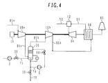
- FIG. 4 shows a recuperated-cycle gas turbine system having an intercooling system of compressor according to an embodiment of the present invention.
- the recuperated-cycle gas turbine system having the intercooling system shown in the first embodiment provides an effect of cooling compressed air by 100°C or more and the amount of humidification for the compressed air is 0.6 % by mass of air.
- the present embodiment indicates a recuperated-cycle gas turbine system having an intercooling system which provides a smaller effect of cooling compressed air and accordingly a larger effect of humidifying compressed air than the system shown in the first embodiment.
- the system shown in the present embodiment differs from the system shown in the first embodiment in that neither the heat exchanger 90 nor the cooling water 91 is used. After the flow rate has been adjusted by means of the regulating valve 84 without cooling, the discharge water of the circulating pump 6 is supplied to the liquid distributor 80 located above the packing.
- Figs. 6A to 6C show graphs of distributions of temperature, absolute humidity, and amount of humidification in terms of height positions at the location of packing 71 in the cooling tower 36 of the present embodiment.
- Figs 6A, 6B, and 6C indicate temperature, absolute humidity, and amount of humidification, respectively.
- air solid line
- a liquid film dotted line
- the absolute humidity (dotted line) of humid air on the liquid film surface is higher than the absolute humidity (solid line) of the mainstream air in the entire area of the location of packing 71. Therefore, as shown in Fig. 6C, steam transfers into the mainstream air from the liquid film surface because a difference in the steam pressure acts as motive force. As a result, the absolute humidity in the mainstream air monotonically increases as it flows upward.
- the absolute humidity of the mainstream air and that of the air on the liquid film surface are interchanged at the upper part of the packing. In accordance with the present embodiment, however, they are not interchanged.
- the amount of humidification for air is 3.2 % by mass of air.
- the air temperature at the outlet of the cooling tower is 82°C.
- the air is cooled down to about 90°C in the cooling tower 36.
- Liquid film water dropped from the packing flows down into the reservoir 74 in the cooling tower 36.
- Moisture lost in evaporation is replenished through the feed pump 7 and the regulating valve 38, and is supplied from the circulating pump 6 to the heat exchanger 90 as hot water with a temperature of about 65°C.
- the system shown in the present embodiment differs from the first embodiment in that there is comparatively large volume of makeup water in the cooling tower 36, i.e., the amount of evaporation is about 3.2 % by mass of air for the present embodiment or about 0.6 % by mass of air for the first embodiment.
- An increase in the amount of evaporation by about 3.2 % by mass of air flow rate means that the compressor 10a has compressed humid air with a mass flow rate of 103.2% at compression work required for a mass flow rate of 100%, i.e., the compression power per unit mass flow rate has been reduced.
- the temperature at this time is about 260°C.
- the inlet air temperature and discharge temperature of the compressor 10b are comparatively low (about 82°C and about 260°C, respectively), the compression power can remarkably be reduced in comparison with a case when these temperatures are high.
- Other operations and functions are the same as those of the first embodiment.
- Activation and deactivation methods of the cooling tower 36 according to the present embodiment is almost the same as those of the first embodiment, only with a difference in that the heat exchanger 90 located downstream of the circulating water pump 6 is not activated.
- FIG. 9 shows a steam heat pump system having an intercooling system of compressor according to a third embodiment of the present invention.
- the present embodiment differs from the first and second embodiments in that the fluid which flows in the compressors is steam instead of air.
- the present embodiment mainly includes an evaporator 42 which evaporates liquid water 35 with the heat of warm water 40 introduced from outside under conditions below the atmospheric pressure to generate steam; compressors 110a, 110b, 110c, and 110d driven by a drive unit (not shown), which pressurize the steam generated by the evaporator 42; and a discharge pipe 25 which supplies the hot steam pressurized by the above-mentioned compressor 110d to a target location.
- Compressors 110a, 110b, 110c, and 110d are connected in series on the same shaft and configured to gradually raise the steam pressure.
- characteristic components of the present embodiment includes a cooling tower 136a connected to a discharge pipe 186a of the compressor 110a, a cooling tower 136b connected to a discharge pipe 186b of the compressor 110b, and a cooling tower 136c connected to a discharge pipe 186c of the compressor 110c.
- These cooling towers 136a, 136b, and 136c are respectively provided with circulating pumps 6a, 6b, and 6c which recirculate circulating water, dropped to the bottom of the tower, to the upper part above packing 71.
- required amount of makeup water 31 can be supplied to an evaporator 42 by means of a makeup water pump 5 and a regulating valve 83.
- Liquid water 35 of the evaporator 42 can be supplied to the cooling tower 136a by means of a feed pump 7 and a regulating valve 38a. Furthermore, discharge pipes of circulating pumps 6a and 6b of the cooling towers 136a and 136b are respectively connected to the cooling towers 136b and 136c so as to supply discharge water. These pipes are respectively provided with regulating valves 38b and 38c. Structure and function of the cooling towers 136a, 136b, and 136c are almost the same as those of the cooling tower 36 of the first embodiment. However, if the internal pressure of the cooling tower 36 is lower than the pressure outside the system like the present embodiment, a pressurizing pump (not shown) is located on a pipe 79 to discharge liquidus water by making the pressure thereof higher than the pressure outside the system.
- a pressurizing pump (not shown) is located on a pipe 79 to discharge liquidus water by making the pressure thereof higher than the pressure outside the system.
- Warm water 40 warmed to about 70°C by an external heat source is supplied to the evaporator 42.
- An example of external heat source used is exhaust heat from a factory, a garbage incineration plant, a thermal power station, a combustion engine, etc.
- the liquid water 35 of the above-mentioned evaporator 42 is retained at about 63°C through indirect heat exchange with the warm water 40.
- the liquid water is retained at about 63°C, for example, by controlling the supply flow rate and temperature of the warm water 40.
- the surface of the liquid water 35 retained at about 63°C will be in gas-liquid equilibrium between 63°C steam with a saturated steam pressure of about 23 kPa and liquidus water with a temperature of about 63°C.
- the air at the upper space in the evaporator 42 has been discharged and the space is filled with steam having an absolute pressure of about 23 kPa.
- steam with a volume according to the inlet capacity of the compressor 110a is absorbed through an inlet pipe 185a. With this absorption, the liquid water 35 continuously evaporates from the surface thereof to generate steam, depriving large volume of evaporation latent heat from the liquid water 35. This deprived heat is covered through heat exchange with the warm water 40.
- the steam with a temperature of about 63°C and a pressure of about 23kPa which has been absorbed by the compressor 110a is pressurized by the compressor 110a up to about 48 kPa to become superheated steam with a temperature of about 145°C.
- This superheated steam with a temperature of about 145°C flows into the cooling tower 136a through a gas distributor 70 in the cooling tower 136a and is subject to gas-liquid contact with the liquid film of hot water at temperature lower than about 80°C or the saturation temperature sprinkled from the liquid distributor 80, on the surface of the packing 71.
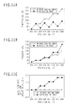
- Figs. 10A to 10C shows graphs of distributions of temperature, flow rate, and steam pressure in terms of height positions at the location of packing 71 in the cooling tower 36 of the present embodiment.
- Figs. 10A, 10B, and 10C indicate temperature, flow rate, and steam pressure, respectively.
- the sprinkled hot water flows down to the surface of the packing 71 while forming a liquid film.
- hot water is heated through heat transmission based on the temperature difference from the hot superheated steam, becoming hotter as it flows downward, as shown in Fig. 10A.
- the upper limit temperature to which the hot water is heated is about 80°C or the saturation temperature for the internal pressure of the tower.
- hot water is heated through heat transmission based on the temperature difference by the superheated steam with a temperature of about 145°C, and accordingly hot water with a temperature of about 80°C flowing down on the surface of the packing is heated.
- This heat quantity is used not for temperature rise of hot water since the saturation temperature in the tower is about 80°C but as latent heat with which hot water evaporates. Then, as shown in Fig. 10B, part of the hot water becomes steam. With this effect, the mass flow rate of the steam increases by about 5 percent after it has passed the packing. On the other hand, sensible heat is deprived from the superheated steam by the hot water and the temperature decreases as the superheated steam flows upward, as shown in Fig. 10A.
- the evaporating water is pure steam which contains no impurities. If solid matters, metal ions, oxides, or other impurities are contained in makeup water, they remain in the liquid film water and condense.
- the steam added to the mainstream steam in the cooling tower 136 contains no impurities, and accordingly compressors and devices located downstream of the cooling tower 136 are not affected.
- the use of the cooling tower 36 of the present embodiment makes it possible to suppress the degradation of the reliability of compressors and gauges, even without using makeup water from which impurities have been removed to an infinitesimal level.
- the temperature of the sprinkled water which ran down from the packing becomes about 80°C or the saturation temperature. Then, the sprinkled water drops into the reservoir 74 in the cooling tower 136a for collection. Since the amount of water which flows down decreases by evaporation as shown in Fig. 10B, the water level is measured with a water gauge 78, the regulating valve 38 is automatically controlled, and makeup water is supplied from the pipe 75 to maintain the amount of water of the reservoir 74. Through mixing with low-temperature water, the water temperature of the reservoir 74 becomes lower than about 80°C or the saturation temperature by several degrees.
- the temperature of the superheated steam decreases to about 80°C or the saturation temperature in the cooling tower 136, resulting in a slight increase in the flow rate.
- the energy of sensible heat of the superheated steam has been transformed into energy of latent heat, resulting in decreased temperature of the steam and increased flow rate. Since the compressor 110a requires only the power for compressing the steam of the flow rate before increase, steam of more amount of mass flow rate has been compressed with less compression power.
- Fine mist called entrainment is generated from the liquid film surface by a shearing force between the liquid film flowing down on the surface of the packing 71 and the steam flowing upward.
- the steam and fine mist which flow upward in the path of the packing 71 pass the packing 71 and then flow into the demister 72 at the upper part.
- the demister 72 eliminates most of mist, and dry steam at the saturation temperature coming out of the cooling tower 36a flows into the compressor 10b through a pipe 73.
- the purpose of eliminating mist is to prevent droplets from hitting the rotational section of the compressor and prevent mechanical corrosion called erosion from occurring.
- mist caught by the demister gathers together and has become large droplets, they drop by the gravity and then flow down on the packing surface as sprinkling water.
- the compressor 110b of the present embodiment compresses steam with a temperature lower than that of steam compressed without intercooling. Therefore, when compressing steam with the same pressure ratio, it can be compressed with less power.
- Discharge steam of the compressor 110b of the present embodiment is superheated steam having a pressure of about 95 kPa and a temperature of about 158°C.
- the superheated steam is cooled by the cooling tower 136b nearly to the saturation temperature with the same operation as that explained for the cooling tower 136a and then adjusted to steam with slightly increased mass flow rate.
- the superheated steam is cooled down nearly to the saturation temperature by the cooling tower 136c to increase the mass flow rate.
- the steam temperature at the inlet of the compressor 110d becomes about 117°C and the pressure becomes about 179 kPa; and the steam temperature at the outlet of the compressor 110d becomes about 187°C and the pressure becomes about 312 kPa.
- This superheating steam is supplied to a heat application facility through the discharge pipe 25.
- the compressors 110b, 110c, and 110d can compress steam with more amount of mass flow rate with less compression power through operation of the cooling towers 136a, 136b, and 136c, respectively. Since each compressor compresses saturated steam at temperature lower than that of the superheated steam, compression can be performed with less power. As the entire system, more amount of steam can be compressed with less power and the cooling efficiency increases synergistically.
- Figs. 11A to 11C shows transitions of temperature, pressure, and mass flow rate in two cases when the cooling tower 136 of the present embodiment is operated and when it is not operated.
- Figs. 11A, 11B, and 11C indicate temperature, pressure, and mass flow rate, respectively.
- the temperature of a discharge pipe 186d of the compressor 110d is about 187°C as shown by the solid line of Fig. 11A in the case where the cooling tower is operated or about 370°C as shown by the dotted line in the case where the cooling tower is not operated.
- the discharge pressure is about 312 kPa in the former case and about 206 kPa in the latter case.
- the utility value of steam largely differs for pressure of about 312 kPa and about 206 kPa.
- the cooling tower 136 is operated, the amount of steam increases 1.17 times; otherwise, the amount of increase is zero.
- a water source at as close temperature as possible was planned to be used as a source of makeup water for the reservoir 74 in the cooling towers 136a, 136b, and 136c, it may be possible to directly supply water from the low-temperature makeup water 31 to respective cooling tower. Also in this case, basic operations are almost the same. However, since the temperature of distribution water from each liquid distributor 80 decreases, sensible heat deprived from the superheated steam increases and accordingly the amount of steam generated decreases, but an effect of cooling the mainstream steam increases.
- the present embodiment assumes a mechanical pump as the circulating pump 6 and the feed pump 7, it is also possible to configure a steam jet pump using higher-pressure steam of the discharge pipe 25 and the discharge pipe 186. In this case, it is possible to simplify devices and, in comparison with a mechanical pump, decrease the possibility of leak of fluid from the shaft seal part and mixing of impurities from outside.
- a method of activating the steam heat pump system according to the present embodiment will be explained below.
- water is injected into the cooling towers 136a, 136b, and 136c up to a predetermined water level.
- regulating valves 84a, 84b, and 84c are opened to sprinkle water to the packing 71 of the cooling towers 136a, 136b, and 136c, and circulate water in the cooling towers by means of circulating pumps 6a, 6b, and 6c, respectively.
- the compressors 110a, 110b, 110c, and 110d are driven to gradually discharge air present in the inlet pipe 185, the discharge pipe 186, and the cooling tower 136 through the discharge pipe 25 and an exhaust gas stack (not shown) into atmosphere, based on fluid drive effect of the compressors.
- the upper space of the evaporator 42 will be filled with steam having an absolute pressure of about 23kPa. Furthermore, in the cooling towers 136a, 136b, and 136c, when the compressors 110a, 110b, 110c, and 110d have been driven, the temperature and pressure will reach the steady state and activation completes. In the course of temperature rise, the heat of steam is used to increase the temperature of the cooling tower 136, the inlet pipe 185, and the discharge pipe 186 which were low temperature at the time of activation, and part of the steam condenses. This condensate water is caught by the demister 72 in the cooling tower 136, and flows down into the reservoir 74. If there is large amount of condensation of steam at the time of activation, the water level of the reservoir 74 rises and therefore the regulating valve 39 of the pipe 79 is automatically controlled to discharge the liquidus water out of the system.
- Each of the above-mentioned embodiments uses a plurality of compressors, and the cooling tower 36 and the cooling tower 136 are located between compressors.
- the present invention is not limited to a case when a plurality of compressors are used but applicable to a case when a single multi-stage compressor is used.
- a multi-stage compressor is used, the same effect as shown in each embodiment can be obtained by preparing the cooling tower 36 and the cooling tower 136 between stages of the compressor.
Landscapes
- Engineering & Computer Science (AREA)
- Mechanical Engineering (AREA)
- General Engineering & Computer Science (AREA)
- Chemical & Material Sciences (AREA)
- Combustion & Propulsion (AREA)
- Physics & Mathematics (AREA)
- Thermal Sciences (AREA)
- Structures Of Non-Positive Displacement Pumps (AREA)
Applications Claiming Priority (1)
| Application Number | Priority Date | Filing Date | Title |
|---|---|---|---|
| JP2006174723A JP4311415B2 (ja) | 2006-06-26 | 2006-06-26 | 冷却装置,冷却装置を用いたガスタービンシステム,冷却機構を用いたヒートポンプシステム,冷却方法,冷却装置の運転方法 |
Publications (2)
| Publication Number | Publication Date |
|---|---|
| EP1873375A2 true EP1873375A2 (de) | 2008-01-02 |
| EP1873375A3 EP1873375A3 (de) | 2014-05-14 |
Family
ID=38227731
Family Applications (1)
| Application Number | Title | Priority Date | Filing Date |
|---|---|---|---|
| EP07012501.8A Withdrawn EP1873375A3 (de) | 2006-06-26 | 2007-06-26 | Kühlsystem für einen Verdichter einer Gasturbine |
Country Status (3)
| Country | Link |
|---|---|
| US (2) | US8240122B2 (de) |
| EP (1) | EP1873375A3 (de) |
| JP (1) | JP4311415B2 (de) |
Cited By (5)
| Publication number | Priority date | Publication date | Assignee | Title |
|---|---|---|---|---|
| RU2418991C1 (ru) * | 2009-11-17 | 2011-05-20 | Общество с ограниченной ответственностью "Газпром трансгаз Казань" | Способ перекачки газа (варианты) и компрессорная станция для его осуществления (варианты) |
| US8192144B2 (en) | 2007-09-28 | 2012-06-05 | Hitachi, Ltd. | Compressor and heat pump system |
| CN103032172A (zh) * | 2011-10-03 | 2013-04-10 | 通用电气公司 | 使用固定床涓流塔的除雾/除湿 |
| WO2017144761A1 (es) * | 2016-02-26 | 2017-08-31 | Desco Sanchez Alejandro | Turbina de gas, y método de operación asociado, con dos etapas de compresión y enfriamiento intermedio mediante máquina frigorífica |
| FR3111416A1 (fr) * | 2020-06-12 | 2021-12-17 | Clauger | Desurchauffeur de fluide frigorigene sous forme gazeuse et installation mettant en œuvre un cycle frigorifique associee |
Families Citing this family (15)
| Publication number | Priority date | Publication date | Assignee | Title |
|---|---|---|---|---|
| JP4972708B2 (ja) * | 2009-01-30 | 2012-07-11 | 株式会社日立製作所 | 蒸気を利用するプラント及びそのプラントの運転方法並びに蒸気供給装置及び蒸気供給方法 |
| WO2011033559A1 (ja) * | 2009-09-16 | 2011-03-24 | 株式会社日立製作所 | 熱併給発電プラント及びバイオマス改質複合発電プラント |
| WO2011061169A1 (en) * | 2009-11-18 | 2011-05-26 | Shell Internationale Research Maatschappij B.V. | Method of handling a boil off gas stream and an apparatus therefor |
| US9546574B2 (en) * | 2010-12-28 | 2017-01-17 | Rolls-Royce Corporation | Engine liquid injection |
| US20120060535A1 (en) * | 2011-03-04 | 2012-03-15 | General Electric Company | Heat pump water heater with external inlet tube |
| FR2983245B1 (fr) | 2011-11-25 | 2014-01-10 | Air Liquide | Procede et appareil d'alimentation en azote d'une chambre de combustion |
| ITCO20120030A1 (it) * | 2012-06-06 | 2013-12-07 | Nuovo Pignone Srl | Compressori ad alto rapporto di pressione con intercooler multiplo e relativi metodi |
| CN103277346B (zh) * | 2013-06-28 | 2015-06-24 | 唐山怡人鼓风机制造有限公司 | 可水冷却降温的多级鼓风机 |
| KR101582297B1 (ko) * | 2013-12-30 | 2016-01-06 | 선테코 유한회사 | 기계식 증기 재압축기를 위한 과열증기 냉각장치 |
| CN105102195B (zh) * | 2014-02-11 | 2017-10-13 | 刘凯 | 泵式蒸压系统及其蒸汽和压力的提供方法 |
| US10767561B2 (en) * | 2014-10-10 | 2020-09-08 | Stellar Energy Americas, Inc. | Method and apparatus for cooling the ambient air at the inlet of gas combustion turbine generators |
| CN107036319B (zh) * | 2016-02-04 | 2020-10-02 | 松下知识产权经营株式会社 | 制冷循环装置 |
| US10895172B2 (en) * | 2017-04-11 | 2021-01-19 | Siemens Aktiengesellschaft | Preservation method |
| CN112302964B (zh) * | 2020-10-29 | 2022-07-08 | 西安西热节能技术有限公司 | 一种独立凝汽式汽动给水泵效率的测定方法 |
| CN115888149A (zh) * | 2022-11-17 | 2023-04-04 | 广东凯链环保科技有限公司 | 一种蒸馏系统及蒸馏方法 |
Family Cites Families (27)
| Publication number | Priority date | Publication date | Assignee | Title |
|---|---|---|---|---|
| US2784571A (en) * | 1957-03-12 | Evaporative air cycle cooler | ||
| US1471112A (en) * | 1919-12-13 | 1923-10-16 | B F Sturtevant Co | Apparatus for cooling air |
| US2407165A (en) * | 1941-06-21 | 1946-09-03 | Kreitner Johann | Method and means for improving power production in combustion turbines |
| US2372846A (en) * | 1942-08-05 | 1945-04-03 | Nettel Frederick | Water distillation |
| US4051888A (en) * | 1973-07-07 | 1977-10-04 | Daikin Kogyo Co., Ltd. | Low temperature energy carrying apparatus and method |
| DE2638983A1 (de) * | 1976-08-30 | 1978-03-02 | Kurt Dipl Chem Dr Dannhaeuser | Verfahren und anordnung zur kuehlleistungsgesteuerten regelung der abflutwassermenge in wasser-rueckkuehlern |
| FR2404737A1 (fr) * | 1977-09-28 | 1979-04-27 | Uniscrew Ltd | Machine motrice a injection d'eau |
| JPS55160265A (en) * | 1979-04-25 | 1980-12-13 | Gen Electric | Multiistage open cycle heat pump |
| JPS5786600A (en) | 1980-11-18 | 1982-05-29 | Setsuo Yamamoto | Gas compressor |
| JPH03128281A (ja) | 1989-10-16 | 1991-05-31 | Fujitsu Ltd | 熱転写インクシートの製造方法 |
| JPH03279683A (ja) | 1990-03-28 | 1991-12-10 | Hitachi Ltd | 多段圧縮機 |
| JP3128281B2 (ja) | 1991-09-09 | 2001-01-29 | ダイセル化学工業株式会社 | 新規な化合物及び分離剤 |
| US5669217A (en) * | 1995-09-25 | 1997-09-23 | Anderson; J. Hilbert | Method and apparatus for intercooling gas turbines |
| ATE218673T1 (de) * | 1996-07-10 | 2002-06-15 | Vattenfall Ab Publ | Verfahren und vorrichtung zum liefern von mechanischer arbeit und, wenn gewünscht, wärme in einem gasverdampfungsturbinenprozess |
| JPH11270352A (ja) * | 1998-03-24 | 1999-10-05 | Mitsubishi Heavy Ind Ltd | 吸気冷却型ガスタービン発電設備及び同発電設備を用いた複合発電プラント |
| US6484508B2 (en) * | 1998-07-24 | 2002-11-26 | General Electric Company | Methods for operating gas turbine engines |
| EP1257349B1 (de) * | 2000-02-23 | 2008-08-13 | Schlom, Leslie | Wärmetauscher zum kühlen und zur verwendung im vorkühler der turbinenluft-aufbereitung |
| US20010054354A1 (en) * | 2000-06-21 | 2001-12-27 | Baudat Ned P. | Direct turbine air chiller/scrubber system |
| GB0211350D0 (en) * | 2002-05-16 | 2002-06-26 | Rolls Royce Plc | A gas turbine engine |
| JP4179496B2 (ja) * | 2002-10-08 | 2008-11-12 | 川崎重工業株式会社 | 常圧燃焼タービンシステム |
| JP2004300928A (ja) | 2003-03-28 | 2004-10-28 | Tokyo Electric Power Co Inc:The | 多段圧縮機、ヒートポンプ、並びに熱利用装置 |
| JP4100316B2 (ja) | 2003-09-30 | 2008-06-11 | 株式会社日立製作所 | ガスタービン設備 |
| DE10355353A1 (de) * | 2003-11-25 | 2005-07-21 | Alstom Technology Ltd | Verfahren und Vorrichtung zum Kühlen einer Gasströmung |
| JP2005274070A (ja) | 2004-03-25 | 2005-10-06 | Shinei Giken:Kk | 過熱蒸気の減温方法及びその装置 |
| JP5151014B2 (ja) | 2005-06-30 | 2013-02-27 | 株式会社日立製作所 | ヒートポンプ装置及びヒートポンプの運転方法 |
| US7712301B1 (en) * | 2006-09-11 | 2010-05-11 | Gas Turbine Efficiency Sweden Ab | System and method for augmenting turbine power output |
| JP4371278B2 (ja) * | 2007-08-07 | 2009-11-25 | 株式会社日立製作所 | 高湿分利用ガスタービン設備 |
-
2006
- 2006-06-26 JP JP2006174723A patent/JP4311415B2/ja not_active Expired - Fee Related
-
2007
- 2007-06-25 US US11/767,805 patent/US8240122B2/en not_active Expired - Fee Related
- 2007-06-26 EP EP07012501.8A patent/EP1873375A3/de not_active Withdrawn
-
2012
- 2012-07-23 US US13/555,888 patent/US8402735B2/en not_active Expired - Fee Related
Cited By (5)
| Publication number | Priority date | Publication date | Assignee | Title |
|---|---|---|---|---|
| US8192144B2 (en) | 2007-09-28 | 2012-06-05 | Hitachi, Ltd. | Compressor and heat pump system |
| RU2418991C1 (ru) * | 2009-11-17 | 2011-05-20 | Общество с ограниченной ответственностью "Газпром трансгаз Казань" | Способ перекачки газа (варианты) и компрессорная станция для его осуществления (варианты) |
| CN103032172A (zh) * | 2011-10-03 | 2013-04-10 | 通用电气公司 | 使用固定床涓流塔的除雾/除湿 |
| WO2017144761A1 (es) * | 2016-02-26 | 2017-08-31 | Desco Sanchez Alejandro | Turbina de gas, y método de operación asociado, con dos etapas de compresión y enfriamiento intermedio mediante máquina frigorífica |
| FR3111416A1 (fr) * | 2020-06-12 | 2021-12-17 | Clauger | Desurchauffeur de fluide frigorigene sous forme gazeuse et installation mettant en œuvre un cycle frigorifique associee |
Also Published As
| Publication number | Publication date |
|---|---|
| US20120282080A1 (en) | 2012-11-08 |
| JP2008002413A (ja) | 2008-01-10 |
| US8240122B2 (en) | 2012-08-14 |
| US8402735B2 (en) | 2013-03-26 |
| JP4311415B2 (ja) | 2009-08-12 |
| US20090056303A1 (en) | 2009-03-05 |
| EP1873375A3 (de) | 2014-05-14 |
Similar Documents
| Publication | Publication Date | Title |
|---|---|---|
| US8402735B2 (en) | Cooling apparatus, gas turbine system using cooling apparatus, heat pump system using cooling system, cooling method, and method for operating cooling apparatus | |
| JP2877098B2 (ja) | ガスタービン,コンバインドサイクルプラント及び圧縮機 | |
| US6247302B1 (en) | Gas turbine power plant | |
| CN101059101B (zh) | 燃气轮机进口调节系统和方法 | |
| US6634165B2 (en) | Control system for gas turbine inlet-air water-saturation and supersaturation system | |
| JPH0587651B2 (de) | ||
| US9657585B2 (en) | Axial compressor and operation method of the same | |
| JP2008175149A (ja) | 圧縮機の吸気噴霧装置 | |
| US20050066664A1 (en) | Gas turbine installation | |
| US20110173947A1 (en) | System and method for gas turbine power augmentation | |
| JPH1172027A (ja) | 排気再循環型コンバインドプラント | |
| JP2001173459A (ja) | ガスタービンの氷結防止運転方法 | |
| CN105841407A (zh) | 一种空调稳压节能器及方法 | |
| JPH11173162A5 (de) | ||
| JP2009133318A (ja) | 複数の中間冷却器を備えた圧縮機を有するシステム,冷却方法 | |
| JPS63248931A (ja) | 圧縮機入口空気水分の氷結防止法 | |
| JP2980095B2 (ja) | ガスタービン,コンバインドサイクルプラント及び圧縮機 | |
| CN116717379B (zh) | 一种适用于燃气轮机进气冷却的步进式空气冷却系统 | |
| JP3567090B2 (ja) | ガスタービン,コンバインドサイクルプラント及び圧縮機 | |
| JP5483625B2 (ja) | ガスタービンシステム | |
| JP4923010B2 (ja) | 吸気に水を噴霧する圧縮機を有する設備 | |
| JP2010112259A (ja) | 蒸気圧縮装置 | |
| JP2006097596A (ja) | ガスタービン設備とその制御装置,ガスタービン設備の制御方法及びタービン冷却部の冷却方法 | |
| JPH1193692A (ja) | コンバインドサイクルシステムとその夏期における吸気冷却方法 | |
| IL107530A (en) | Method of and apparatus for augmenting power produced by gas turbines |
Legal Events
| Date | Code | Title | Description |
|---|---|---|---|
| PUAI | Public reference made under article 153(3) epc to a published international application that has entered the european phase |
Free format text: ORIGINAL CODE: 0009012 |
|
| AK | Designated contracting states |
Kind code of ref document: A2 Designated state(s): AT BE BG CH CY CZ DE DK EE ES FI FR GB GR HU IE IS IT LI LT LU LV MC MT NL PL PT RO SE SI SK TR |
|
| AX | Request for extension of the european patent |
Extension state: AL BA HR MK YU |
|
| 17P | Request for examination filed |
Effective date: 20090408 |
|
| PUAL | Search report despatched |
Free format text: ORIGINAL CODE: 0009013 |
|
| AK | Designated contracting states |
Kind code of ref document: A3 Designated state(s): AT BE BG CH CY CZ DE DK EE ES FI FR GB GR HU IE IS IT LI LT LU LV MC MT NL PL PT RO SE SI SK TR |
|
| AX | Request for extension of the european patent |
Extension state: AL BA HR MK RS |
|
| RIC1 | Information provided on ipc code assigned before grant |
Ipc: F02C 7/143 20060101AFI20140404BHEP |
|
| AKX | Designation fees paid |
Designated state(s): DE FR GB IT |
|
| AXX | Extension fees paid |
Extension state: HR Extension state: MK Extension state: BA Extension state: AL Extension state: RS |
|
| STAA | Information on the status of an ep patent application or granted ep patent |
Free format text: STATUS: THE APPLICATION HAS BEEN WITHDRAWN |
|
| 18W | Application withdrawn |
Effective date: 20150512 |