EP1873386B1 - Buse à fente variable pour nacelle de ventilateur de moteur à turbine à gaz - Google Patents
Buse à fente variable pour nacelle de ventilateur de moteur à turbine à gaz Download PDFInfo
- Publication number
- EP1873386B1 EP1873386B1 EP07252550A EP07252550A EP1873386B1 EP 1873386 B1 EP1873386 B1 EP 1873386B1 EP 07252550 A EP07252550 A EP 07252550A EP 07252550 A EP07252550 A EP 07252550A EP 1873386 B1 EP1873386 B1 EP 1873386B1
- Authority
- EP
- European Patent Office
- Prior art keywords
- nacelle
- assembly
- fan
- flap
- recited
- Prior art date
- Legal status (The legal status is an assumption and is not a legal conclusion. Google has not performed a legal analysis and makes no representation as to the accuracy of the status listed.)
- Active
Links
Images


Classifications
-
- F—MECHANICAL ENGINEERING; LIGHTING; HEATING; WEAPONS; BLASTING
- F01—MACHINES OR ENGINES IN GENERAL; ENGINE PLANTS IN GENERAL; STEAM ENGINES
- F01D—NON-POSITIVE DISPLACEMENT MACHINES OR ENGINES, e.g. STEAM TURBINES
- F01D17/00—Regulating or controlling by varying flow
- F01D17/10—Final actuators
- F01D17/12—Final actuators arranged in stator parts
- F01D17/14—Final actuators arranged in stator parts varying effective cross-sectional area of nozzles or guide conduits
- F01D17/141—Final actuators arranged in stator parts varying effective cross-sectional area of nozzles or guide conduits by means of shiftable members or valves obturating part of the flow path
-
- F—MECHANICAL ENGINEERING; LIGHTING; HEATING; WEAPONS; BLASTING
- F02—COMBUSTION ENGINES; HOT-GAS OR COMBUSTION-PRODUCT ENGINE PLANTS
- F02K—JET-PROPULSION PLANTS
- F02K1/00—Plants characterised by the form or arrangement of the jet pipe or nozzle; Jet pipes or nozzles peculiar thereto
- F02K1/06—Varying effective area of jet pipe or nozzle
- F02K1/12—Varying effective area of jet pipe or nozzle by means of pivoted flaps
- F02K1/1207—Varying effective area of jet pipe or nozzle by means of pivoted flaps of one series of flaps hinged at their upstream ends on a fixed structure
-
- F—MECHANICAL ENGINEERING; LIGHTING; HEATING; WEAPONS; BLASTING
- F02—COMBUSTION ENGINES; HOT-GAS OR COMBUSTION-PRODUCT ENGINE PLANTS
- F02K—JET-PROPULSION PLANTS
- F02K1/00—Plants characterised by the form or arrangement of the jet pipe or nozzle; Jet pipes or nozzles peculiar thereto
- F02K1/06—Varying effective area of jet pipe or nozzle
- F02K1/15—Control or regulation
-
- F—MECHANICAL ENGINEERING; LIGHTING; HEATING; WEAPONS; BLASTING
- F02—COMBUSTION ENGINES; HOT-GAS OR COMBUSTION-PRODUCT ENGINE PLANTS
- F02K—JET-PROPULSION PLANTS
- F02K3/00—Plants including a gas turbine driving a compressor or a ducted fan
- F02K3/02—Plants including a gas turbine driving a compressor or a ducted fan in which part of the working fluid by-passes the turbine and combustion chamber
- F02K3/04—Plants including a gas turbine driving a compressor or a ducted fan in which part of the working fluid by-passes the turbine and combustion chamber the plant including ducted fans, i.e. fans with high volume, low pressure outputs, for augmenting the jet thrust, e.g. of double-flow type
- F02K3/06—Plants including a gas turbine driving a compressor or a ducted fan in which part of the working fluid by-passes the turbine and combustion chamber the plant including ducted fans, i.e. fans with high volume, low pressure outputs, for augmenting the jet thrust, e.g. of double-flow type with front fan
-
- F—MECHANICAL ENGINEERING; LIGHTING; HEATING; WEAPONS; BLASTING
- F02—COMBUSTION ENGINES; HOT-GAS OR COMBUSTION-PRODUCT ENGINE PLANTS
- F02K—JET-PROPULSION PLANTS
- F02K3/00—Plants including a gas turbine driving a compressor or a ducted fan
- F02K3/02—Plants including a gas turbine driving a compressor or a ducted fan in which part of the working fluid by-passes the turbine and combustion chamber
- F02K3/04—Plants including a gas turbine driving a compressor or a ducted fan in which part of the working fluid by-passes the turbine and combustion chamber the plant including ducted fans, i.e. fans with high volume, low pressure outputs, for augmenting the jet thrust, e.g. of double-flow type
- F02K3/075—Plants including a gas turbine driving a compressor or a ducted fan in which part of the working fluid by-passes the turbine and combustion chamber the plant including ducted fans, i.e. fans with high volume, low pressure outputs, for augmenting the jet thrust, e.g. of double-flow type controlling flow ratio between flows
-
- F—MECHANICAL ENGINEERING; LIGHTING; HEATING; WEAPONS; BLASTING
- F05—INDEXING SCHEMES RELATING TO ENGINES OR PUMPS IN VARIOUS SUBCLASSES OF CLASSES F01-F04
- F05D—INDEXING SCHEME FOR ASPECTS RELATING TO NON-POSITIVE-DISPLACEMENT MACHINES OR ENGINES, GAS-TURBINES OR JET-PROPULSION PLANTS
- F05D2260/00—Function
- F05D2260/50—Kinematic linkage, i.e. transmission of position
-
- F—MECHANICAL ENGINEERING; LIGHTING; HEATING; WEAPONS; BLASTING
- F05—INDEXING SCHEMES RELATING TO ENGINES OR PUMPS IN VARIOUS SUBCLASSES OF CLASSES F01-F04
- F05D—INDEXING SCHEME FOR ASPECTS RELATING TO NON-POSITIVE-DISPLACEMENT MACHINES OR ENGINES, GAS-TURBINES OR JET-PROPULSION PLANTS
- F05D2270/00—Control
- F05D2270/60—Control system actuates means
- F05D2270/62—Electrical actuators
Definitions
- the present invention relates to a gas turbine engine, and more particularly to a turbofan gas turbine engine having a variable area nozzle structure within the fan nacelle thereof.
- air is pressurized in a compressor and mixed with fuel in a combustor for generating hot combustion gases which flow downstream through turbine stages that extract energy therefrom.
- a high pressure turbine powers the compressor, and a low pressure turbine powers a fan disposed upstream of the compressor.
- Combustion gases are discharged from the core engine through a core exhaust nozzle, and fan air is discharged through an annular fan exhaust nozzle defined at least partially by a nacelle surrounding the core engine.
- a majority of propulsion thrust is provided by the pressurized fan air discharged through the fan exhaust nozzle, the remaining thrust provided from the combustion gases discharged through the core exhaust nozzle.
- variable area nozzle for a gas turbine engine fan nacelle.
- Nacelle assemblies having flaps provided in a wall of the fan nacelle are disclosed in US 2005/151012 A1 , US 2005/103933 A1 and US 2005/126174 A1 .
- a nacelle assembly for a gas turbine engine as set forth in claim 1.
- the synchronizing ring is mounted within a multitude of slider tracks that are affixed within the fan nacelle.
- An actuator assembly selectively rotates the synchronizing ring relative the static ring to adjust the flap assembly through the linkage to vary the annular fan exit area defined by the FVAN through which fan air is discharged.
- the linkage for each flap of the flap assembly may generally include a hinge beam which extends from each flap, a slider block assembly and a hinge pin mounted to the slider block assembly.
- the slider blocks are located within a slot formed in the synchronizing ring.
- the slots formed within the synchronizing ring are non-circumferentially located about the engine longitudinal centerline axis.
- the actuator assembly rotates the synchronizing ring circumferentially about the engine longitudinal centerline axis.
- the slider block assembly moves within the slot such that a rod which extends from the hinge beam translates slider block radial motion to a rod tangential moment about the hinge.
- the resulting flap assembly moment about the flap hinge varies the diameter of the flap assembly and thus the annular fan exit area within the fan nacelle.
- the present invention therefore provides an effective, relatively inexpensive variable area nozzle for a gas turbine engine fan nacelle.
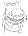
- FIG 1A illustrates a general partial fragmentary view of a gas turbofan engine 10 suspended from an engine pylon 12 as typical of an aircraft designed for subsonic operation.
- the engine 10 is preferably a high-bypass turbofan aircraft engine.
- the engine 10 typically includes in serial flow communication a fan 14 with a low pressure compressor, a high pressure compressor 16, an annular combustor 18, high pressure turbine 20, and low pressure turbine 22.
- air is pressurized in the compressor and mixed with fuel in the combustor for generating hot combustion gases which flow through the high and low pressure turbines that extract energy therefrom.
- the high pressure turbine powers the compressor through a shaft therebetween, and the low pressure turbine powers the fan through another shaft therebetween.
- the exemplary turbofan engine 10 is in the form of a high bypass ratio engine mounted within a nacelle assembly 24 in which most of the air pressurized by the fan bypasses the core engine itself for generating propulsion thrust.
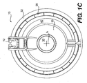
- the fan air F is discharged from the engine 10 through a fan variable area nozzle (FVAN) 28 (also illustrated in Figures 1B and 1C ) defined radially between a core nacelle 30 and a fan nacelle 32.
- the core exhaust gases C are discharged from the core engine through a core exhaust nozzle 34 defined between the core nacelle 30 and a center plug 36 ( Figure 1C ) disposed coaxially therein around an engine longitudinal centerline axis A of the engine 10 and nacelle.
- the FVAN 28 of the fan nacelle 32 coaxially or concentrically surrounds the core nacelle 30 to define a variable diameter nozzle downstream of an annular fan duct D for discharging axially the fan air F pressurized by the upstream fan 14.
- a segment of the FVAN 28 generally includes a synchronizing ring 40, a static ring 42, and a flap assembly 44.
- the flap assembly 44 is pivotally mounted to the static ring 42 at a multitude of hinges 45 and linked to the synchronizing ring 40 through a linkage 46.
- An actuator assembly 48 (only one shown) selectively rotates the synchronizing ring 40 relative the static ring 42 to adjust the flap assembly 44 through the linkage 46 to vary the area defined by the FVAN 28 through which the fan air F is discharged.
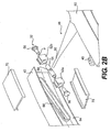
- the linkage 46 for each flap 44a of the flap assembly 44 generally includes a hinge beam 50, a slider block assembly 52 and a hinge pin 54 mounted to the slider block assembly 52 through a fastener 56.
- the slider block assembly 52 preferably includes a first slider block 52a and a second slider block 52b between which the hinge pin 54 is mounted through the fasteners 56 for rotation about the longitudinal axis P thereof.
- the hinge pin 54 includes an aperture 58 which receives a hinge beam rod 60.
- Each flap 44a preferably includes a machined aluminum honeycomb core 62 and carbon fiber skins 64 mounted to the hinge beam 50 ( Figure 3A ).
- Each flap 44a includes a nested tongue and groove arrangement such that the flaps are nested when assembled ( Figure 3B ). That is, each flap 44a engages the adjacent flaps 44a to provide a circumferential seal which defines the exit area.
- the slider blocks 52a, 52b are located within a slot 66 formed in the synchronizing ring 40.
- the slots 66 formed within the synchronizing ring 40 are non-circumferentially located about the engine longitudinal centerline axis A. That is, a mean line M defined by each slot 66 is transverse to a concentric circle S defined by the synchronizing ring 40 about axis A ( Figure 2C ).
- the slots 66 include a radial assembly opening 64 to receive the slider blocks 52a, 52b in an extended length of the slot 66 to facilitate assembly.
- the slider blocks 52a, 52b may be formed of a multitude of pieces to facilitate assembly into a slot 66 which does not include a radial assembly opening 64.
- the synchronizing ring 40 is mounted within a multitude of slider tracks 70 that are affixed within the fan nacelle 32 ( Figure 1B ).
- the actuator assembly 48 includes linear actuators which rotate the synchronizing ring 40 thereby transferring relative significant force through a relatively uncomplicated, low-profile system.
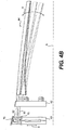
- the actuator assembly 48 rotates the synchronizing ring 40 circumferentially about the engine longitudinal centerline axis A (double headed arrow X; Figure 4A ).
- the slider block assembly 52 moves within the slot 66 such that the hinge beam rod 60 converts radial moment to tangential moment for flap assembly 44.
- the actuator assembly 48 communicates with an engine controller or the like to adjust the position of the FVAN 28.
- other control systems including flight control systems may likewise be usable with the present invention.
Landscapes
- Engineering & Computer Science (AREA)
- Mechanical Engineering (AREA)
- General Engineering & Computer Science (AREA)
- Chemical & Material Sciences (AREA)
- Combustion & Propulsion (AREA)
- Structures Of Non-Positive Displacement Pumps (AREA)
- Control Of Turbines (AREA)
Claims (10)
- Ensemble de nacelle (24) pour moteur à turbine à gaz (10) comprenant :une nacelle de ventilateur (32) délimitée autour d'un axe ;une nacelle de coeur (34) contenue au moins en partie dans ladite nacelle de ventilateur (32) ;un ensemble de volet (44) monté pivotant sur ladite nacelle de ventilateur (32) ;une bague de synchronisation (40) apte à tourner autour dudit axe relativement à ladite nacelle de ventilateur (32) ; et caractérisé par :une timonerie (46) montée sur ladite bague de synchronisation (40) et ledit ensemble de volet (44) pour régler une région annulaire de sortie du ventilateur entre ladite nacelle de ventilateur (32) et ladite nacelle de coeur (34), ledit ensemble de volet (44) délimitant un segment le plus arrière de ladite nacelle de ventilateur (32).
- Ensemble de nacelle selon la revendication 1, comprenant en outre : une bague fixe (42) délimitée autour dudit axe, adjacente à ladite bague de synchronisation (40), ledit ensemble de volet (44) étant monté pivotant sur ladite bague fixe (42).
- Ensemble de nacelle selon la revendication 2, dans lequel ladite bague fixe (42) est disposée entre ladite bague de synchronisation (40) et ledit ensemble de volet (44).
- Ensemble de nacelle selon la revendication 3, dans lequel ledit ensemble de volet (44) comprend une tige de longeron d'articulation (60) qui s'étend à travers ladite bague fixe (42).
- Ensemble de nacelle selon la revendication 4, dans lequel ladite tige de longeron d'articulation (60) coopère avec un bloc coulissant (52a, 52b) qui se déplace dans une encoche (66) délimitée dans ladite bague de synchronisation (40).
- Ensemble de nacelle selon la revendication 5, dans lequel ladite encoche (66) délimite une ligne moyenne transversale à un cercle concentrique délimité par ladite bague de synchronisation (40) autour dudit axe.
- Ensemble de nacelle selon la revendication 5 ou 6, dans lequel ladite tige de longeron d'articulation (60) coopère avec un axe (54) monté sur ledit bloc coulissant (52a, 52b), ledit axe (54) étant rotatif relativement audit bloc coulissant (52a, 52b).
- Ensemble de nacelle selon la revendication 7, dans lequel chaque volet (44a) dudit ensemble de volet (44) comporte un longeron d'articulation (50) et une âme (62) prise en sandwich entre un revêtement supérieur et un revêtement inférieur (64), ladite tige de longeron d'articulation (60) s'étendant à partir dudit longeron d'articulation (50) vers l'opposée de ladite âme (62).
- Ensemble de nacelle selon l'une quelconque des revendications précédentes, comprenant en outre un actionneur linéaire (48) qui fait tourner ladite bague de synchronisation (40) autour dudit axe relativement à ladite bague fixe (42).
- Ensemble de nacelle selon l'une quelconque des revendications précédentes, dans lequel ledit ensemble de volet (44) comporte une pluralité de volets (44a) unis les uns aux autres par un assemblage à languette et rainure.
Applications Claiming Priority (1)
| Application Number | Priority Date | Filing Date | Title |
|---|---|---|---|
| US11/478,009 US7721551B2 (en) | 2006-06-29 | 2006-06-29 | Fan variable area nozzle for a gas turbine engine fan nacelle |
Publications (3)
| Publication Number | Publication Date |
|---|---|
| EP1873386A2 EP1873386A2 (fr) | 2008-01-02 |
| EP1873386A3 EP1873386A3 (fr) | 2010-12-29 |
| EP1873386B1 true EP1873386B1 (fr) | 2012-04-18 |
Family
ID=38542111
Family Applications (1)
| Application Number | Title | Priority Date | Filing Date |
|---|---|---|---|
| EP07252550A Active EP1873386B1 (fr) | 2006-06-29 | 2007-06-22 | Buse à fente variable pour nacelle de ventilateur de moteur à turbine à gaz |
Country Status (3)
| Country | Link |
|---|---|
| US (4) | US7721551B2 (fr) |
| EP (1) | EP1873386B1 (fr) |
| JP (1) | JP4593598B2 (fr) |
Families Citing this family (58)
| Publication number | Priority date | Publication date | Assignee | Title |
|---|---|---|---|---|
| US7721551B2 (en) * | 2006-06-29 | 2010-05-25 | United Technologies Corporation | Fan variable area nozzle for a gas turbine engine fan nacelle |
| US7966824B2 (en) * | 2006-08-09 | 2011-06-28 | The Boeing Company | Jet engine nozzle exit configurations and associated systems and methods |
| US7870722B2 (en) * | 2006-12-06 | 2011-01-18 | The Boeing Company | Systems and methods for passively directing aircraft engine nozzle flows |
| US7966826B2 (en) * | 2007-02-14 | 2011-06-28 | The Boeing Company | Systems and methods for reducing noise from jet engine exhaust |
| WO2008108847A1 (fr) * | 2007-03-05 | 2008-09-12 | United Technologies Corporation | Buse d'éjection de zone variable de soufflante pour une nacelle à soufflante de turbine à gaz à système d'actionnement à anneau d'entraînement |
| US7963099B2 (en) * | 2007-05-21 | 2011-06-21 | General Electric Company | Fluted chevron exhaust nozzle |
| US7926285B2 (en) * | 2007-07-18 | 2011-04-19 | General Electric Company | Modular chevron exhaust nozzle |
| WO2009029401A2 (fr) | 2007-08-08 | 2009-03-05 | Rohr, Inc. | Buse de ventilateur à surface variable avec écoulement de dérivation |
| US9759087B2 (en) | 2007-08-08 | 2017-09-12 | Rohr, Inc. | Translating variable area fan nozzle providing an upstream bypass flow exit |
| US8047004B2 (en) * | 2008-02-12 | 2011-11-01 | The Boeing Company | Stave and ring CMC nozzle |
| US7716932B2 (en) * | 2008-07-24 | 2010-05-18 | Spirit Aerosystems, Inc. | Dilating fan duct nozzle |
| US9181899B2 (en) * | 2008-08-27 | 2015-11-10 | General Electric Company | Variable slope exhaust nozzle |
| US9816441B2 (en) * | 2009-03-30 | 2017-11-14 | United Technologies Corporation | Gas turbine engine with stacked accessory components |
| US20110004388A1 (en) * | 2009-07-01 | 2011-01-06 | United Technologies Corporation | Turbofan temperature control with variable area nozzle |
| US8781737B2 (en) * | 2009-11-20 | 2014-07-15 | Qualcomm Incorporated | Spatial alignment determination for an inertial measurement unit (IMU) |
| US9057286B2 (en) * | 2010-03-30 | 2015-06-16 | United Technologies Corporation | Non-circular aft nacelle cowling geometry |
| US10041442B2 (en) | 2010-06-11 | 2018-08-07 | United Technologies Corporation | Variable area fan nozzle |
| US8549834B2 (en) | 2010-10-21 | 2013-10-08 | United Technologies Corporation | Gas turbine engine with variable area fan nozzle |
| JP5724391B2 (ja) * | 2011-01-07 | 2015-05-27 | 株式会社Ihi | エンジン排気ノズル及び航空機エンジン |
| US8720183B2 (en) * | 2011-03-02 | 2014-05-13 | Spirit Aerosystems, Inc. | Thrust reverser translating sleeve assembly |
| US8613398B2 (en) | 2011-06-17 | 2013-12-24 | General Electric Company | Apparatus and methods for linear actuation of flow altering components of jet engine nozzle |
| GB201112045D0 (en) * | 2011-07-14 | 2011-08-31 | Rolls Royce Plc | A gas turbine engine exhaust nozzle |
| US9359972B2 (en) | 2011-08-31 | 2016-06-07 | United Technologies Corporation | Multi axis slide carriage system |
| US8375699B1 (en) | 2012-01-31 | 2013-02-19 | United Technologies Corporation | Variable area fan nozzle with wall thickness distribution |
| US9394852B2 (en) | 2012-01-31 | 2016-07-19 | United Technologies Corporation | Variable area fan nozzle with wall thickness distribution |
| FR2988439B1 (fr) * | 2012-03-20 | 2014-11-28 | Aircelle Sa | Tuyere a section variable et nacelle pour turboreacteur d'aeronef equipee d'une telle tuyere |
| US9091230B2 (en) | 2012-05-16 | 2015-07-28 | The Boeing Company | Linked ring petal actuation for variable area fan nozzle |
| US9194296B2 (en) | 2012-05-18 | 2015-11-24 | Pratt & Whitney Canada Corp. | Inner bypass duct wall attachment |
| FR2993932B1 (fr) * | 2012-07-27 | 2015-09-25 | Aircelle Sa | Dispositif d'entrainement de volets notamment pour tuyere adaptative |
| US9989009B2 (en) * | 2012-10-31 | 2018-06-05 | The Boeing Company | Methods and apparatus for sealing variable area fan nozzles of jet engines |
| WO2014172016A2 (fr) | 2013-03-04 | 2014-10-23 | United Technologies Corporation | Inverseur de poussée à portes pivotantes comportant une buse de section variable |
| US9845768B2 (en) | 2013-03-13 | 2017-12-19 | Rolls-Royce North American Technologies, Inc. | Three stream, variable area, vectorable nozzle |
| WO2014143267A1 (fr) * | 2013-03-15 | 2014-09-18 | United Technologies Corporation | Moteur à turbine à gaz à faible bruit de soufflante |
| US9581145B2 (en) * | 2013-05-14 | 2017-02-28 | The Boeing Company | Shape memory alloy actuation system for variable area fan nozzle |
| US10144524B2 (en) * | 2013-06-14 | 2018-12-04 | Rohr, Inc. | Assembly for mounting a turbine engine to a pylon |
| US9488130B2 (en) | 2013-10-17 | 2016-11-08 | Honeywell International Inc. | Variable area fan nozzle systems with improved drive couplings |
| US9863367B2 (en) * | 2013-11-01 | 2018-01-09 | The Boeing Company | Fan nozzle drive systems that lock thrust reversers |
| US10077739B2 (en) * | 2014-04-24 | 2018-09-18 | Rohr, Inc. | Dual actuation system for cascade and thrust reverser panel for an integral cascade variable area fan nozzle |
| US9869190B2 (en) | 2014-05-30 | 2018-01-16 | General Electric Company | Variable-pitch rotor with remote counterweights |
| US9499275B2 (en) * | 2014-10-16 | 2016-11-22 | Rohr, Inc. | Stress-relieving joint between materials with differing coefficients of thermal expansion |
| US10072510B2 (en) | 2014-11-21 | 2018-09-11 | General Electric Company | Variable pitch fan for gas turbine engine and method of assembling the same |
| US9669938B2 (en) | 2015-01-16 | 2017-06-06 | United Technologies Corporation | Upper bifi frame for a gas turbine engine and methods therefor |
| US10329945B2 (en) * | 2015-04-21 | 2019-06-25 | Siemens Energy, Inc. | High performance robust gas turbine exhaust with variable (adaptive) exhaust diffuser geometry |
| US9810178B2 (en) | 2015-08-05 | 2017-11-07 | General Electric Company | Exhaust nozzle with non-coplanar and/or non-axisymmetric shape |
| US10100653B2 (en) | 2015-10-08 | 2018-10-16 | General Electric Company | Variable pitch fan blade retention system |
| US10570926B2 (en) | 2015-12-03 | 2020-02-25 | The Boeing Company | Variable-geometry ducted fan |
| DE202017006759U1 (de) * | 2016-02-05 | 2018-04-24 | Bayern-Chemie Gesellschaft Für Flugchemische Antriebe Mbh | Vorrichtung und System zur Steuerung von Flugkörpern und Kill-Vehicles, die mit gelförmigen Treibstoffen betrieben wird |
| GB201609071D0 (en) | 2016-05-24 | 2016-07-06 | Rolls Royce Plc | Aircraft gas turbine engine nacelle |
| US10724543B2 (en) * | 2017-08-11 | 2020-07-28 | Raytheon Technologies Corporation | Bridge bracket for variable-pitch vane system |
| FR3083577B1 (fr) * | 2018-07-06 | 2021-05-07 | Safran Aircraft Engines | Turbomachine pour aeronef comportant une pluralite de vannes de decharge variable et procede de commande |
| US11056880B1 (en) * | 2020-03-31 | 2021-07-06 | Western Digital Technologies, Inc. | Snapback electrostatic discharge protection for electronic circuits |
| FR3115834B1 (fr) * | 2020-11-03 | 2023-11-10 | Safran Aircraft Engines | Tuyere d'ejection des gaz de combustion a geometrie variable, pour turboreacteur d'aeronef |
| US11674435B2 (en) | 2021-06-29 | 2023-06-13 | General Electric Company | Levered counterweight feathering system |
| US11795964B2 (en) | 2021-07-16 | 2023-10-24 | General Electric Company | Levered counterweight feathering system |
| US11668311B2 (en) * | 2021-11-05 | 2023-06-06 | Techtronic Cordless Gp | Blowers with variable nozzles |
| CN114671033B (zh) * | 2022-04-28 | 2023-01-17 | 中国航发沈阳发动机研究所 | 一种高隐身低尾阻轻质的非接触式飞发搭接结构 |
| CN115614179B (zh) * | 2022-08-31 | 2024-04-05 | 中国航发四川燃气涡轮研究院 | 喉道面积的调节机构 |
| US12601271B2 (en) | 2022-10-21 | 2026-04-14 | General Electric Company | Variable pitch fan of a gas turbine engine |
Family Cites Families (51)
| Publication number | Priority date | Publication date | Assignee | Title |
|---|---|---|---|---|
| US2778190A (en) * | 1950-06-08 | 1957-01-22 | Republic Aviat Corp | Variable area nozzle for jet engines |
| US2980199A (en) * | 1956-03-16 | 1961-04-18 | Rolls Royce | Variable area jet propulsion nozzles |
| US2934966A (en) * | 1957-11-12 | 1960-05-03 | Westinghouse Electric Corp | Control apparatus |
| US3892358A (en) * | 1971-03-17 | 1975-07-01 | Gen Electric | Nozzle seal |
| US4044973A (en) * | 1975-12-29 | 1977-08-30 | The Boeing Company | Nacelle assembly and mounting structures for a turbofan jet propulsion engine |
| US4147027A (en) * | 1976-04-06 | 1979-04-03 | Grumman Aerospace Corporation | Thrust reverser nozzle |
| US4205813A (en) * | 1978-06-19 | 1980-06-03 | General Electric Company | Thrust vectoring apparatus for a VTOL aircraft |
| US4505443A (en) * | 1978-12-29 | 1985-03-19 | General Dynamics Corporation | Propulsion system for a V/STOL airplane |
| US4301980A (en) * | 1978-12-29 | 1981-11-24 | General Dynamics Corporation | Propulsion system for a V/STOL airplane |
| US4410150A (en) * | 1980-03-03 | 1983-10-18 | General Electric Company | Drag-reducing nacelle |
| US4391409A (en) * | 1980-09-30 | 1983-07-05 | The Boeing Company | Positioning and control system for fan thrust reverser cowls in a turbofan engine |
| US4466587A (en) * | 1981-12-21 | 1984-08-21 | General Electric Company | Nacelle installation |
| GB8811698D0 (en) * | 1988-05-18 | 1988-10-05 | Dowty Defence & Air Systems Lt | Hydraulic actuator system |
| US5261605A (en) * | 1990-08-23 | 1993-11-16 | United Technologies Corporation | Axisymmetric nozzle with gimbled unison ring |
| FR2676779B1 (fr) * | 1991-05-21 | 1994-06-03 | Lair Jean Pierre | Tuyere a section variable. |
| US5261227A (en) * | 1992-11-24 | 1993-11-16 | General Electric Company | Variable specific thrust turbofan engine |
| US5315821A (en) * | 1993-02-05 | 1994-05-31 | General Electric Company | Aircraft bypass turbofan engine thrust reverser |
| GB9424495D0 (en) * | 1994-12-05 | 1995-01-25 | Short Brothers Plc | Aerodynamic low drag structure |
| JPH08192484A (ja) * | 1995-01-13 | 1996-07-30 | Showa Aircraft Ind Co Ltd | 接着装置 |
| FR2737256B1 (fr) * | 1995-07-26 | 1997-10-17 | Aerospatiale | Turboreacteur a double flux a portes d'inversion de poussee non soumises au flux secondaire dans leur position inactive |
| DE69514224T2 (de) * | 1995-09-13 | 2000-08-10 | Societe De Construction Des Avions Hurel-Dubois (S.A.), Meudon-La-Foret | Elektrohydraulische Schubumkehrvorrichtung mit zwei Klappen |
| FR2742482B1 (fr) * | 1995-12-19 | 1998-02-06 | Hurel Dubois Avions | Inverseur de poussee a tuyere a section reglable pour moteur d'avion a reaction |
| US5806302A (en) * | 1996-09-24 | 1998-09-15 | Rohr, Inc. | Variable fan exhaust area nozzle for aircraft gas turbine engine with thrust reverser |
| ES2136528B1 (es) | 1996-12-26 | 2000-05-01 | Sener Ing & Sist | Perfeccionamientos en toberas axisimetricas de geometria variable y orientacion del flujo destinadasa propulsores de turbina de gas |
| US6109021A (en) * | 1998-07-22 | 2000-08-29 | General Electric Company | Vectoring nozzle calibration |
| US6212877B1 (en) * | 1998-09-04 | 2001-04-10 | General Electric Company | Vectoring ring support and actuation mechanism for axisymmetric vectoring nozzle with a universal joint |
| ES2224580T3 (es) * | 1999-05-13 | 2005-03-01 | Industria De Turbo Propulsores S.A. | Mecanismo de control del area de salida en toberas convergente-divergentes. |
| US6318070B1 (en) * | 2000-03-03 | 2001-11-20 | United Technologies Corporation | Variable area nozzle for gas turbine engines driven by shape memory alloy actuators |
| US6340135B1 (en) * | 2000-05-30 | 2002-01-22 | Rohr, Inc. | Translating independently mounted air inlet system for aircraft turbofan jet engine |
| US6938408B2 (en) * | 2001-04-26 | 2005-09-06 | Propulsion Vectoring, L.P. | Thrust vectoring and variable exhaust area for jet engine nozzle |
| US6598386B2 (en) * | 2001-10-16 | 2003-07-29 | Honeywell International, Inc. | Jet engine thrust reverser system having torque limited synchronization |
| US6983588B2 (en) * | 2002-01-09 | 2006-01-10 | The Nordam Group, Inc. | Turbofan variable fan nozzle |
| WO2003099654A2 (fr) * | 2002-05-21 | 2003-12-04 | The Nordam Group, Inc. | Buse de reacteur a double flux bifurquee |
| US6769868B2 (en) * | 2002-07-31 | 2004-08-03 | General Electric Company | Stator vane actuator in gas turbine engine |
| FR2846378B1 (fr) * | 2002-10-25 | 2006-06-30 | Hispano Suiza Sa | Inverseur de poussee electromecanique pour turboreacteur a synchronisation des dispositifs de verrouillage |
| US6966175B2 (en) * | 2003-05-09 | 2005-11-22 | The Nordam Group, Inc. | Rotary adjustable exhaust nozzle |
| US7093793B2 (en) * | 2003-08-29 | 2006-08-22 | The Nordam Group, Inc. | Variable cam exhaust nozzle |
| US7264203B2 (en) * | 2003-10-02 | 2007-09-04 | The Nordam Group, Inc. | Spider actuated thrust reverser |
| US7458221B1 (en) * | 2003-10-23 | 2008-12-02 | The United States Of America As Represented By The Administrator Of The National Aeronautics And Space Administration | Variable area nozzle including a plurality of convexly vanes with a crowned contour, in a vane to vane sealing arrangement and with nonuniform lengths |
| US7032835B2 (en) * | 2004-01-28 | 2006-04-25 | United Technologies Corporation | Convergent/divergent nozzle with modulated cooling |
| US7216831B2 (en) * | 2004-11-12 | 2007-05-15 | The Boeing Company | Shape changing structure |
| US7624567B2 (en) * | 2005-09-20 | 2009-12-01 | United Technologies Corporation | Convergent divergent nozzle with interlocking divergent flaps |
| US8235325B2 (en) * | 2005-10-04 | 2012-08-07 | United Technologies Corporation | Fan variable area nozzle positional measurement system |
| US7721551B2 (en) * | 2006-06-29 | 2010-05-25 | United Technologies Corporation | Fan variable area nozzle for a gas turbine engine fan nacelle |
| US20080028763A1 (en) * | 2006-08-03 | 2008-02-07 | United Technologies Corporation | Thermal management system with thrust recovery for a gas turbine engine fan nacelle assembly |
| EP2074301B1 (fr) | 2006-10-12 | 2016-02-24 | United Technologies Corporation | Turboréacteur à double-flux avec une tuyère de poussée controlée pour décollage et atterrissage |
| EP2074313B1 (fr) * | 2006-10-12 | 2014-07-09 | United Technologies Corporation | Tuyère à section variable à soufflante avec actionneur électromécanique |
| US9194328B2 (en) * | 2006-10-12 | 2015-11-24 | United Technologies Corporation | Fan variable area nozzle for a gas turbine engine fan nacelle with sliding actuation system |
| WO2008045050A1 (fr) | 2006-10-12 | 2008-04-17 | United Technologies Corporation | Turbine à gaz avec tuyère à section variable à soufflante, ensemble nacelle et méthode permettant de varier la surface de sortie de la tuyère de soufflante |
| US7797944B2 (en) * | 2006-10-20 | 2010-09-21 | United Technologies Corporation | Gas turbine engine having slim-line nacelle |
| US7976138B2 (en) * | 2006-12-21 | 2011-07-12 | Eastman Kodak Company | Data-providing-component securing mechanism for printing apparatus reservoir |
-
2006
- 2006-06-29 US US11/478,009 patent/US7721551B2/en active Active
- 2006-10-17 US US11/582,219 patent/US7637095B2/en not_active Expired - Fee Related
-
2007
- 2007-06-22 EP EP07252550A patent/EP1873386B1/fr active Active
- 2007-06-25 JP JP2007165776A patent/JP4593598B2/ja active Active
-
2009
- 2009-11-11 US US12/616,750 patent/US8769925B2/en active Active
- 2009-11-11 US US12/616,759 patent/US8806850B2/en active Active
Also Published As
| Publication number | Publication date |
|---|---|
| US20100050596A1 (en) | 2010-03-04 |
| EP1873386A2 (fr) | 2008-01-02 |
| JP2008008292A (ja) | 2008-01-17 |
| JP4593598B2 (ja) | 2010-12-08 |
| US7637095B2 (en) | 2009-12-29 |
| EP1873386A3 (fr) | 2010-12-29 |
| US7721551B2 (en) | 2010-05-25 |
| US8769925B2 (en) | 2014-07-08 |
| US20080001039A1 (en) | 2008-01-03 |
| US20080000235A1 (en) | 2008-01-03 |
| US20100139285A1 (en) | 2010-06-10 |
| US8806850B2 (en) | 2014-08-19 |
Similar Documents
| Publication | Publication Date | Title |
|---|---|---|
| EP1873386B1 (fr) | Buse à fente variable pour nacelle de ventilateur de moteur à turbine à gaz | |
| US11396847B2 (en) | Flutter sensing and control system for a gas turbine engine | |
| US8727267B2 (en) | Variable contraction ratio nacelle assembly for a gas turbine engine | |
| EP1470328B1 (fr) | Tuyère de turbofan et procédé de réduction du bruit dans une telle tuyêre | |
| EP2504552B1 (fr) | Rail de support pour buse de soufflante à section variable | |
| EP2074312B1 (fr) | Tuyère à section variable pour nacelle de soufflante de moteur à turbine à gaz équipée d' un système d'actionnement coulissant | |
| US8857151B2 (en) | Corrugated core cowl for a gas turbine engine | |
| EP2069629B1 (fr) | Tuyère à section variable d'une soufflante de turboréacteur double flux équipée d'un système à pièces rapportées pivotantes | |
| EP2061964B1 (fr) | Moteur à turboréacteur à structure interne fixée comprenant des passages carénés | |
| EP2074319B1 (fr) | Moteur à turbine à gaz avec tuyère d'éjection variable, ensemble nacelle de ce moteur et procédé de fonctionnement correspondant | |
| EP2069630B1 (fr) | Agencement de nacelle et procédé associé | |
| EP1916405B1 (fr) | Tuyère à section variable de contrôle du vecteur de poussée pour nacelle de soufflante de turboréacteur | |
| EP2074307B1 (fr) | Capot mobile de nacelle centrale avec éléments de volet aérodynamiques | |
| EP1995442B1 (fr) | Valve de moteur à turbine | |
| EP2074303B1 (fr) | Profil aérodynamique pour capot de corps central de turbine à gaz | |
| EP4108897B1 (fr) | Système de propulsion d'aéronef doté d'une entrée à surface variable |
Legal Events
| Date | Code | Title | Description |
|---|---|---|---|
| PUAI | Public reference made under article 153(3) epc to a published international application that has entered the european phase |
Free format text: ORIGINAL CODE: 0009012 |
|
| AK | Designated contracting states |
Kind code of ref document: A2 Designated state(s): AT BE BG CH CY CZ DE DK EE ES FI FR GB GR HU IE IS IT LI LT LU LV MC MT NL PL PT RO SE SI SK TR |
|
| AX | Request for extension of the european patent |
Extension state: AL BA HR MK YU |
|
| PUAL | Search report despatched |
Free format text: ORIGINAL CODE: 0009013 |
|
| AK | Designated contracting states |
Kind code of ref document: A3 Designated state(s): AT BE BG CH CY CZ DE DK EE ES FI FR GB GR HU IE IS IT LI LT LU LV MC MT NL PL PT RO SE SI SK TR |
|
| AX | Request for extension of the european patent |
Extension state: AL BA HR MK RS |
|
| RIC1 | Information provided on ipc code assigned before grant |
Ipc: F02K 1/12 20060101ALI20101124BHEP Ipc: F02K 3/075 20060101ALI20101124BHEP Ipc: F02K 3/06 20060101ALI20101124BHEP Ipc: F02K 1/15 20060101ALI20101124BHEP Ipc: F02K 1/06 20060101AFI20071009BHEP |
|
| 17P | Request for examination filed |
Effective date: 20110629 |
|
| AKX | Designation fees paid |
Designated state(s): DE FR GB |
|
| GRAP | Despatch of communication of intention to grant a patent |
Free format text: ORIGINAL CODE: EPIDOSNIGR1 |
|
| GRAS | Grant fee paid |
Free format text: ORIGINAL CODE: EPIDOSNIGR3 |
|
| GRAA | (expected) grant |
Free format text: ORIGINAL CODE: 0009210 |
|
| AK | Designated contracting states |
Kind code of ref document: B1 Designated state(s): DE FR GB |
|
| REG | Reference to a national code |
Ref country code: GB Ref legal event code: FG4D |
|
| REG | Reference to a national code |
Ref country code: DE Ref legal event code: R096 Ref document number: 602007022071 Country of ref document: DE Effective date: 20120614 |
|
| PLBE | No opposition filed within time limit |
Free format text: ORIGINAL CODE: 0009261 |
|
| STAA | Information on the status of an ep patent application or granted ep patent |
Free format text: STATUS: NO OPPOSITION FILED WITHIN TIME LIMIT |
|
| 26N | No opposition filed |
Effective date: 20130121 |
|
| REG | Reference to a national code |
Ref country code: FR Ref legal event code: ST Effective date: 20130228 |
|
| PG25 | Lapsed in a contracting state [announced via postgrant information from national office to epo] |
Ref country code: FR Free format text: LAPSE BECAUSE OF NON-PAYMENT OF DUE FEES Effective date: 20120702 |
|
| REG | Reference to a national code |
Ref country code: DE Ref legal event code: R097 Ref document number: 602007022071 Country of ref document: DE Effective date: 20130121 |
|
| REG | Reference to a national code |
Ref country code: DE Ref legal event code: R082 Ref document number: 602007022071 Country of ref document: DE Representative=s name: SCHMITT-NILSON SCHRAUD WAIBEL WOHLFROM PATENTA, DE |
|
| REG | Reference to a national code |
Ref country code: DE Ref legal event code: R082 Ref document number: 602007022071 Country of ref document: DE Representative=s name: SCHMITT-NILSON SCHRAUD WAIBEL WOHLFROM PATENTA, DE Ref country code: DE Ref legal event code: R081 Ref document number: 602007022071 Country of ref document: DE Owner name: UNITED TECHNOLOGIES CORP. (N.D.GES.D. STAATES , US Free format text: FORMER OWNER: UNITED TECHNOLOGIES CORP., HARTFORD, CONN., US |
|
| REG | Reference to a national code |
Ref country code: DE Ref legal event code: R081 Ref document number: 602007022071 Country of ref document: DE Owner name: RAYTHEON TECHNOLOGIES CORPORATION (N.D.GES.D.S, US Free format text: FORMER OWNER: UNITED TECHNOLOGIES CORP. (N.D.GES.D. STAATES DELAWARE), FARMINGTON, CONN., US Ref country code: DE Ref legal event code: R081 Ref document number: 602007022071 Country of ref document: DE Owner name: RTX CORPORATION (N.D.GES.D. STAATES DELAWARE),, US Free format text: FORMER OWNER: UNITED TECHNOLOGIES CORP. (N.D.GES.D. STAATES DELAWARE), FARMINGTON, CONN., US |
|
| P01 | Opt-out of the competence of the unified patent court (upc) registered |
Effective date: 20230519 |
|
| PGFP | Annual fee paid to national office [announced via postgrant information from national office to epo] |
Ref country code: DE Payment date: 20250520 Year of fee payment: 19 |
|
| PGFP | Annual fee paid to national office [announced via postgrant information from national office to epo] |
Ref country code: GB Payment date: 20250520 Year of fee payment: 19 |
|
| REG | Reference to a national code |
Ref country code: DE Ref legal event code: R081 Ref document number: 602007022071 Country of ref document: DE Owner name: RTX CORPORATION (N.D.GES.D. STAATES DELAWARE),, US Free format text: FORMER OWNER: RAYTHEON TECHNOLOGIES CORPORATION (N.D.GES.D.STAATES DELAWARE), ARLINGTON, VA, US |