EP1873416A1 - Leistungskopplungsvorrichtung - Google Patents
Leistungskopplungsvorrichtung Download PDFInfo
- Publication number
- EP1873416A1 EP1873416A1 EP07010915A EP07010915A EP1873416A1 EP 1873416 A1 EP1873416 A1 EP 1873416A1 EP 07010915 A EP07010915 A EP 07010915A EP 07010915 A EP07010915 A EP 07010915A EP 1873416 A1 EP1873416 A1 EP 1873416A1
- Authority
- EP
- European Patent Office
- Prior art keywords
- strut
- coupling member
- coupling device
- coupling
- Prior art date
- Legal status (The legal status is an assumption and is not a legal conclusion. Google has not performed a legal analysis and makes no representation as to the accuracy of the status listed.)
- Granted
Links
- 230000008878 coupling Effects 0.000 title claims abstract description 188
- 238000010168 coupling process Methods 0.000 title claims abstract description 188
- 238000005859 coupling reaction Methods 0.000 title claims abstract description 188
- 230000002457 bidirectional effect Effects 0.000 abstract description 17
- 230000007935 neutral effect Effects 0.000 abstract description 11
- 230000033001 locomotion Effects 0.000 description 10
- 239000012530 fluid Substances 0.000 description 7
- XEEYBQQBJWHFJM-UHFFFAOYSA-N Iron Chemical compound [Fe] XEEYBQQBJWHFJM-UHFFFAOYSA-N 0.000 description 6
- 230000005540 biological transmission Effects 0.000 description 5
- 239000002184 metal Substances 0.000 description 4
- 229910052751 metal Inorganic materials 0.000 description 4
- 229910052742 iron Inorganic materials 0.000 description 3
- 230000008901 benefit Effects 0.000 description 2
- 238000006243 chemical reaction Methods 0.000 description 1
- 230000001419 dependent effect Effects 0.000 description 1
- 238000010586 diagram Methods 0.000 description 1
- 230000007246 mechanism Effects 0.000 description 1
- 230000000149 penetrating effect Effects 0.000 description 1
- 230000001105 regulatory effect Effects 0.000 description 1
- 230000000717 retained effect Effects 0.000 description 1
- 239000000126 substance Substances 0.000 description 1
Images




Classifications
-
- F—MECHANICAL ENGINEERING; LIGHTING; HEATING; WEAPONS; BLASTING
- F16—ENGINEERING ELEMENTS AND UNITS; GENERAL MEASURES FOR PRODUCING AND MAINTAINING EFFECTIVE FUNCTIONING OF MACHINES OR INSTALLATIONS; THERMAL INSULATION IN GENERAL
- F16D—COUPLINGS FOR TRANSMITTING ROTATION; CLUTCHES; BRAKES
- F16D41/00—Freewheels or freewheel clutches
- F16D41/12—Freewheels or freewheel clutches with hinged pawl co-operating with teeth, cogs, or the like
- F16D41/125—Freewheels or freewheel clutches with hinged pawl co-operating with teeth, cogs, or the like the pawl movement having an axial component
-
- F—MECHANICAL ENGINEERING; LIGHTING; HEATING; WEAPONS; BLASTING
- F16—ENGINEERING ELEMENTS AND UNITS; GENERAL MEASURES FOR PRODUCING AND MAINTAINING EFFECTIVE FUNCTIONING OF MACHINES OR INSTALLATIONS; THERMAL INSULATION IN GENERAL
- F16D—COUPLINGS FOR TRANSMITTING ROTATION; CLUTCHES; BRAKES
- F16D41/00—Freewheels or freewheel clutches
- F16D41/12—Freewheels or freewheel clutches with hinged pawl co-operating with teeth, cogs, or the like
- F16D41/14—Freewheels or freewheel clutches with hinged pawl co-operating with teeth, cogs, or the like the effective stroke of the pawl being adjustable
-
- F—MECHANICAL ENGINEERING; LIGHTING; HEATING; WEAPONS; BLASTING
- F16—ENGINEERING ELEMENTS AND UNITS; GENERAL MEASURES FOR PRODUCING AND MAINTAINING EFFECTIVE FUNCTIONING OF MACHINES OR INSTALLATIONS; THERMAL INSULATION IN GENERAL
- F16D—COUPLINGS FOR TRANSMITTING ROTATION; CLUTCHES; BRAKES
- F16D41/00—Freewheels or freewheel clutches
- F16D41/12—Freewheels or freewheel clutches with hinged pawl co-operating with teeth, cogs, or the like
- F16D41/16—Freewheels or freewheel clutches with hinged pawl co-operating with teeth, cogs, or the like the action being reversible
Definitions
- the present description relates to a power coupling device which can switch a torque transmission state between two coupling members.
- a power coupling device which may engage and disengage two rotational coupling members depending on a direction of torque transfer. When a torque transfer between the two coupling members is in one direction, the power coupling device engages the two coupling members and transfers torque from one to the other. When the torque transfer is in the other direction, the power coupling device disengages the two rotational members and permits a freewheeling overrunning motion between the two coupling members.
- the retainer plate retains the first strut in a pocket of the first coupling member, and instead a second strut pivoted at its end opposite to that of the first strut in the circumferential direction penetrates a hole of the retainer plates. Then, the relative rotation between the first and second coupling members in the other direction is permitted by the second strut running over the first pivot, but it is prevented in the one direction by the second strut engaging with the recess of the second coupling member.
- the coupling device of the '965 patents can lock the relative rotation between the first and second coupling members in either of the forward and reverse directions, and a forward lock state and a reverse lock state can be achieved. However, it can not enable a free rotation in the both directions nor a complete engagement between the first and second coupling members.
- a power coupling device comprising first and second coupling members, at least one of which is capable of rotating about a common axis and relative to each other.
- the first coupling member has a pocket, and the second coupling member has notches.
- the power coupling member also comprises first and second struts arranged at least partly in the pocket. Each of the first and second struts is urged to at least partly emerge from the pocket and capable of engaging with one of the notches.
- the first strut is capable of transmitting torque between the first and second coupling members only in a first direction
- the second strut is capable of transmitting torque between the first and second coupling members only in a second direction that is opposite to the first direction.
- the power coupling device further comprises first and second retainer plates at least partly arranged between the first and second coupling members capable of moving in a plane perpendicular to the common axis and independently from each other.
- the first retainer plate has a first hole which the first or second strut can pass through.
- the second retainer plates has a second hole which the first or second strut can pass through when the second hole is aligned with the first hole and the first or second strut.
- the first and second retainer plates by moving the first and second retainer plates independently, it is possible to individually retract the first and second struts at least partly into the pocket and let them at least partly emerge from the pocket.
- the second retainer plate at least partly covers the first hole, none of the first and second struts engages with any of the recesses of the second coupling member. Therefore, the first and second coupling members can rotate relative to each other in either direction, and a neutral state can be achieved.
- the first and second coupling members can be engaged with each other in the both directions, and a bidirectional lock state can be achieved.
- this power coupling device can achieve the neutral state and the bidirectional lock state in addition to forward and reverse lock states.
- first and second retainer plates may be configured to be capable of rotating about the common axis so that a common shaft can be arranged penetrating the first and second coupling members and retainer plates.
- said first strut is pivoted at its pivot end
- said second strut is pivoted at its pivot end that is opposite to said pivot end of said first strut in a circumferential direction of said first and second coupling members.
- swing ends of said first and second struts that are substantially opposite to said pivot ends are urged to emerge from said pocket.
- the power coupling device further comprises springs at least partly arranged in said pockets to urge said swing ends of said first and second struts.
- said first and second retainer plates are capable of rotating about said common axis .
- the power coupling device further comprises a casing which fixedly supports said first coupling member and rotatably supports said second coupling member.
- said pocket comprises: a first pocket which accommodates said first strut and a first spring that urges said first strut out of said first pocket; and a second pocket which accommodates said second strut and a second spring that urges said second strut out of said second pocket.
- the coupling device further comprises: a first actuator capable of moving said first retainer plate; and a second actuator capable of moving said second retainer plate.
- said first hole and said second hole are of same shape and size.
- said first and second plates are of same shape and size.
- a power coupling device comprising: first and second coupling members, at least one of which is capable of rotating about a common axis and relative to each other, said first coupling member having a pocket, said second coupling member having notches; first and second struts arranged at least partly in said pocket, each of said first and second struts being urged to emerge from said pocket and capable of engaging with one of said notches, said first strut being capable of transmitting torque between said first and second coupling members only in a first direction, said second strut being capable of transmitting torque between said first and second coupling members only in a second direction that is opposite to said first direction; and first and second retainer plates arranged between said first and second coupling members capable of rotating about said common axis and independently from each other, said first retainer plate having a first hole which said first or second strut can pass through, said second retainer plate having a second hole which said first or second strut can pass through when said second hole is align
- said pocket comprises: a first pocket which accommodates said first strut and a first spring that urges said first strut out of said first pocket; and a second pocket which accommodates said second strut and a second spring that urges said second strut out of said second pocket.
- said first strut is pivoted at its one end
- said second strut is pivoted at its one end that is opposite to said one end of said first strut in a circumferential direction of said first and second coupling members
- said first spring urges the other end of said first strut
- said second spring urges the other end of said second strut.
- the power coupling device further comprises a casing which fixedly supports said first coupling member and rotatably supports said second coupling member.
- the coupling device further comprises: a first actuator attached to said casing and capable of rotating said first retainer plate; and a second actuator attached to said casing and capable of rotating said second retainer plate.
- said first and second retainer plates are configured to be enable said first and second struts to simultaneously or individually pass through both said first and second holes.
- said first and second plates are configured to be able to simultaneously block said both first and second struts.
- said first and second plates are configured to respectively take two angular positions to enable said first and second struts to individually or simultaneously pass through said first and second holes and to simultaneously be blocked.
- said first hole and said second hole are of same shape and size.
- said first and second plates are of same shape and size.
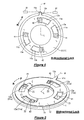
- FIGs 1 through 8 a power coupling device according to a first embodiment of the present description will be described.
- a first coupling member 1 and a second coupling member 2 both of which preferably are formed in a circular disk shape centered in a common axis L (shown in Figures 4 through 8).
- the power coupling device may selectively lock relative rotation between the first coupling member 1 and the second coupling member 2 as described in greater detail below.
- first coupling member 1 may be permanently fixed to a case of a power transmission apparatus such as an automatic transmission of an automotive vehicle.
- the second coupling member 2 may be rotated about the common axis L and selectively locked in either direction. Therefore, the power coupling device 100 may function as a brake. Otherwise, each of the first and second coupling members 1 and 2 may rotate about the common axis L so that the power coupling device may function as a clutch.
- first retainer plate 11 and a second retainer plate 12 at least partly arranged between the first and second coupling members 1 and 2.
- the first coupling member 1, the first retainer plate 11, the second retainer plate 12 and the second coupling member 2 are arranged in this order in the direction of the common axis L.
- the first and second coupling members 1 and 2 are (preferably formed thicker so as to be) capable of transmitting torque between them. On the other hand, preferably neither of the first and second retainer plates 11 and 12 transmits torque so that they are formed thinner.
- the coupling members 1 and 2 and the retainer plates 11 and 12 are made with metal such as an iron based metal.
- first pockets or recesses (concave portion) 21 on an opposing side surface of the first coupling member 1 which faces substantially toward the second coupling member 2.
- the first pockets 21 preferably are angularly spaced with each other by about 180° in the circumferential direction of the first coupling member 1.
- two second pockets 22 preferably also angularly spaced with each other by about 180°.
- the neighboring first and second pockets 21 and 22 preferably are angularly spaced with each other by about 90° and/or have same size and shape.
- two first recesses 31 (only one is illustrated in Figure 1) on a substantially opposing surface of the second coupling member 2 which faces substantially toward the first coupling member 1.
- the two first recesses 31 preferably are arranged angularly spaced with each other by about 180° and angularly corresponding to the two pockets 21 or 22 of the first coupling member 1.
- two second recesses 32 (only one is illustrated in Figure 1) which preferably are arranged angularly spaced with reach other by about 180° and/or substantially angularly corresponding to the two pockets 21 or 22 of the first coupling member 1.
- the neighboring recesses 31 and 32 are angularly spaced with each other by about 90° and formed substantially symmetrically in the circumferential direction around the common axis L. Therefore, the first recesses 31 may be substantially angularly aligned with the first pockets 21, and the second recesses 32 may be substantially angularly aligned with the second pockets 22.
- the first and second retainer plates 11 and 12 can be rotated about the common axis L. They preferably are configured with same shape and size although in Figure 4 they are illustrated slightly different from each other to show clearly the first retainer plate 11 arranged under the second retainer plate 12.
- the first retainer plate 11 has one or more, preferably four holes (openings) 11 a angularly spaced with each other and has one or more non-openings 11 b anywhere else.
- the second retainer plate 12 has one or more, preferably four holes 12a angularly spaced with each other and has one or more non-openings 12b.
- first and second retainer plates 11 and 12 when they are in a predetermined or predeterminable relative angular relationship, they may have their holes 11 a and 12a (preferably perfectly) aligned with each other.
- the holes 11 a and 12a are of an annular shape centered substantially at the common axis L. Their width in the radial direction of the retainer plates 11 and 12 is substantially same as that of the pockets 21 and 22. Their length in the circumferential direction of the retainer plates 11 and 12 is substantially longer than that of the pockets 21 and 22.
- a first strut 41 is arranged in the first pocket 21 of the first coupling member 1, and it is pivoted at its pivot end in the circumferential direction so that a swing end can be retained within the first pocket 21 or can eject from the first pocket 21 toward the second coupling member 2.
- the first strut 41 preferably is made rigid from iron based metal, for example, so as to have a larger torque capacity.
- a second strut 42 is arranged in the second pocket 22 of the first coupling member 1, and it is pivoted at its pivot end in the circumferential direction in the substantially same manner as the first strut 41 is. But, the pivot end of the second strut 42 is arranged opposite to that of the first strut 41 in the circumferential direction.
- the second strut 42 preferably is (also) made rigid from iron based metal.
- first spring 51 acting as a first biasing member to urge the swing end of the first strut 41 to eject from the pocket 21.
- second spring 52 acting as a second biasing member at least partly in the second pocket 22 in the same manner as the first spring 51.
- the first and second springs 51 and 52 preferably are coil springs with same size and/or shape.
- a coil axis of the spring 51 or 52 extends substantially in the radial direction of the first coupling member 1.
- One end 51 a or 52a of the coil spring 51 or 52 contacts with the lower surface of the strut 41 or 42.
- the other end 51 b or 52b contacts with the bottom surface of the pocket 21 or 22.
- an angle between the ends 51 a and 51 b (or 52a and 52b) is smaller than when the strut 41 or 42 ejects from the pocket 21 or 22 as shown in Figure 1.
- a concave spring storage 21 a or 22a at the bottom of the pocket 21 or 22.
- the spring storage 21 a or 22a make it possible to arrange the spring 51 or 52 substantially lower (or longitudinally more outward or displaced) so that the angle between the ends 51 a and 51 b (or 52a and 52b) can be made an appropriate angle even when swing end of the strut 41 or 42 is retracted into the pocket 21 or 22.
- the pocket 21 or 22 may be upwardly tilted by an angle of between about 25 to about 50 degrees e.g. by about 30 or 40 degrees compared to when it is retracted.
- the swing end of the strut 41 or 42 contacts in plane with a contact surface or notch 31 a or 32a of the recess 31 or 32.
- the notch 31 a or 32a is tilted less than another end surface of the recess as shown in Figures 1 through 3.
- the pivot end of the strut 41 or 42 contacts substantially in plane (or substantially in surface contact) with one of end surfaces of the pocket 21 or 22 substantially in the circumferential direction of the first coupling member 1.
- a protruding portion 11c is formed at the periphery of the first retainer plate 11.
- a first actuator 61 is coupled to the protruding portion 11c and attached to the casing.
- a protruding portion 12c is formed at the periphery of the second retainer plate 12, and a second actuator 62 is coupled to the protruding portion 12c and attached to the casing.
- Each of the first and second retainer plates can be rotated about the common axis L and independently from each other by a corresponding one of the first and second actuators 61 and 62.
- the second coupling member 2 is angularly regulated or controlled or locked with respect to the first coupling member 1 in the both directions about the common axis L.
- the both protruding portions 11c and 12c are at a reference angular position ⁇ .
- the all openings 11 a and 11 b of the first and second retainer plates 11 and 12 are perfectly aligned with the pockets 21 and 22.
- the swing end of the first strut 41 ejects from the pocket 21, passes through the openings 11 a and 12a of the first and second retainer plates 11 and 12 and engages with notch 31 a of the first recess 31 as shown in Figure 1.
- the first strut 41 transmits torque from the second coupling member 2 to the first coupling member 1 in the forward direction F or vice versa in the reverse direction R and engages the second coupling member 2 with the first coupling member 1 in the forward direction F.
- the swing end of the second strut 42 at least partly ejects from the pocket 22, penetrates through the openings 11 a and 12a of the first and second retainer plates 11 and 12 and engages with the notch 32a of the second recess 32 as shown in Figure 1.
- the second strut 42 transmits torque from the second coupling member 2 to the first coupling member in the reverse direction R or vice versa in the forward direction F and engages the second coupling member 2 with the first coupling member 1 in the reverse direction R.
- first retainer plate 11 is rotated slightly in the forward direction F from the reference position ⁇
- second retainer plate 12 is rotated slightly in the reverse direction R from the reference position ⁇ to retract the both first and second struts 41 and 42 into the first and second pockets 21 and 22 respectively.
- This achieves a neutral state where neither of the first and second struts 41 and 42 restricts the rotation of the second coupling member 2 in terms of the first coupling member 1.
- the second coupling member 2 can rotate in the forward and reverse directions F and R in this neutral state, where the second retainer plate 12 retracts the first strut 41 and the first retainer plate 11 retracts the second strut 42.
- the first retainer plate 11 is adjusted angularly into one or more positions, preferably into the three positions including the reference position ⁇ while the second retainer plate 12 is adjusted angularly into one or more positions, preferably into the two positions including the reference position ⁇ .
- the combinations of the angular positions of the first and second retainer plates 11 and 12 preferably may achieve the bidirectional lock state, the forward lock state, the reverse lock state, and the neutral state.
- the two actuators 61 and 62 individually and respectively activate the first and second retainer plates 11 and 12 in order to achieve the four states described above. Since the first and second retainer plates 11 and 12 preferably are in the substantially same size and/or shape, the plurality of (preferably four) states may also be achieved by opposite angular relationships between the two plates 11 and 12.
- FIG. 9 there is shown a power coupling device according to a second embodiment of the present description. Same or similar components have the same reference numerals as in the first embodiment described above and will not be explained for simplicity of the description.
- the strut 41 or 42 is attached through a pin 41 to the first coupling member 1 so that the strut 41 or 42 can be pivot about the axis of the pin 41.
- the pin 41 may make the pivot movement of the strut smoother.
- the pin 41 is inserted in a hole opened passing through the strut 41 or 42 in the radial direction of the first coupling member 1.
- the cross section of the hole may be in a substantially circular shape conforming to that of the pin 41. Or, it may be extended in the longitudinal direction of the strut 41 or 42 so that its end at the pivot side may contact to the corresponding end surface of the pocket 21 or 22 and transmit torque between the first and second coupling members 1 and 2 without torque transmission through the pin 41.
- a leaf spring 50 illustrated in Figure 10 may be used as one or all biasing member(s).
- the spring 50, 51 or 52 and its arrangement are not limited to those described above, but they may be any type of spring and its arrangement including a coil spring with its spring force in coil axis direction used which is shown in Figure 6 of U.S. Patent no. 6,186,299 , wherein the corresponding disclosure is included herein by reference.
- the first and second retainer plates 11 and 12 respectively take two angular positions instead of one taking three and the other taking two in the first embodiment. Therefore, the second embodiment can improve accuracy of the retainer position and simplicity of control of the actuators.
- the bidirectional lock state shown in Figure 11 substantially corresponds to that in Figure 4, but the protruding portions 11c and 12c are located differently from in Figure 4. From the bidirectional lock state, by turning the first retainer plate 11 in the forward direction F, the protruding portion 11c of the first retainer plate 11 substantially aligns with the protruding portion 12c of the second retainer plate 12, and the forward lock state is achieved as shown in Figure 12.
- the neutral state may be achieved as shown in Figure 14, for example, by turning the first retainer plate 11 in the forward direction F and turning the second retainer plate 12 in the reverse direction R from the bidirectional lock state in Figure 11 until the protruding portions 11c and 12c of the first and second retainer plates 11 and 12 replace their angular positions with each other.
- a valve body 90 has two cylinders 91 a and 91 b formed therein.
- a first piston 92a and a second piston 92b are arranged respectively in the cylinders 91 a and 91 b so that the pistons are capable of reciprocating in the cylinders.
- one or more electromagnetic actuators may be used.
- Springs 93a and 93b respectively urge the first and second pistons 92a and 92b in the substantially opposite directions.
- the valve body 90 and the first and second pistons 92 and 92b define hydraulic chambers 94a and 94b.
- a hydraulic pump 96 and an accumulator 97 may deliver preferably hydraulic or fluid pressure to the hydraulic or fluid chambers 94a and 94b respectively through switching valves 95a and 95b.
- the switching valve 95a (preferably hydraulically) connects the hydraulic chamber 94a to the pump 96 and the accumulator 97, the hydraulic or fluid pressure displaces the first piston 92a against the force of the spring 93a from one end to the other end of the piston stroke.
- the switching valve 95a drains the hydraulic or fluid pressure in the hydraulic chamber 94a, the spring 93a returns the first piston 92a to the one end of the piston stroke.
- the first piston 92a has the extension arm 98a integrally or unitarily formed therewith, which extends out of the valve body 90 and has a pin 99a arranged at or near its end.
- the pin 99a engages with a concave end of the protruding portion 11c of the first retainer plate 11 so as to convert the linear movement of the first piston 92a to the angular movement of the first retainer plate 11.
- the second piston 92b and related components are configured in the similar or same way and put the same reference numerals with “b” instead of "a” as for the first piston 92a and the related components. Therefore, by operating the switching valve 95b, the second piston 92b is substantially linearly displaced, and the substantially linear movement of the second piston 92b is converted into the substantially angular movement of the second retainer plate 12.
- the hydraulic pump 96 and the accumulator 97 are commonly used for both the first and second pistons 92a and 92b.
- the force of the springs 93a and 93b may be set with respect to the hydraulic or fluid pressure from the pump side so as to achieve the intended end positions of the piston stroke, and the first and second pistons 92a and 92b may be placed accurately in the two stroke end positions. Therefore, the first and second retainer plates 11 and 12 may be accurately placed respectively in the two angular positions.
- the first and second retainer plates 11 and 12 preferably are substantially in the ring shape and capable of rotating about the common axis L. Thereby, a rotational shaft can be readily arranged extending through the first and second retainer plates 11 and 12.
- the first and second pockets 21 and 22 are provided individually for the respective first and second struts 41 and 42 and the related components including the springs 51 and 52. Thereby, any interference between the functions of the first and second struts 41 and 42 can be securely prevented, and flexibility of arrangement of the first and second struts 41 and 42 and related components can be improved.
- the first coupling member 1 is permanently fixed to the casing, and does not rotate. Therefore, the struts 41 and 42 arranged on the first coupling member and the related components do not rotate about the common axis L, and this arrangement can make the operation of the power coupling device more stable.
- the actuators are provided individually for the first and second retainer plates 11 and 12. Thereby, the angular position of the one retainer plate can be readily adjusted without being affected from the angular position of the other retainer plate.
- first coupling member 1, the second coupling member 2, the first retainer plate 11 and the second retainer plate 12 are not limited to the ring shape illustrated in the figures, but they may be any shape pertinent for the power coupling devices including a disk shape or elliptical shape with or without a center hole to at least partly accommodate a shaft.
- the pockets 21 and 22, the struts 41 and 42 and the springs 51 and 52 are arranged in the first coupling members which is not rotating, they may be arranged in one of the first and second coupling members 1 and 2 which is not rotating (the second coupling member 2 in the embodiments).
- an electromagnetic actuator and/or a link mechanism may be provided for converting movement from a single actuator to the movements of the first and second retainer plates 11 and 12 in order to achieve the four states shown in Figures 5 through 8 or the four states shown in Figures 11 through 14.
- first and second retainer plates 11 and 12 may be moved substantially linearly in a plane perpendicular to the common axis L.
- the actuators 61 and 62 may be of hydraulic, actuated by fluid, electric, electromagnetic or any type pertinent to actuate the first and second retainer plates 11 and 12.
- Number of sets of the first or second pocket 21 or 22 and the components therein such as the strut 41 or 42 is not limited to two described above, but may be one or three or more. Also, the number of sets may be different between the first and second struts 41 and 42 and the related components, for example, in a case where magnitude of transmitted torque are different between the rotational directions.
- a power coupling device comprising first and second coupling members, at least one of which is capable of rotating about a common axis and relative to each other.
- the first coupling member has a pocket, and the second coupling member has notches.
- the power coupling member also comprises first and second struts arranged at least partly in the pocket. Each of the first and second struts is urged to emerge from the pocket and capable of engaging with one of the notches.
- the first strut is capable of transmitting torque between the first and second coupling members only in a first direction
- the second strut is capable of transmitting torque between the first and second coupling members only in a second direction that is opposite to the first direction.
- the power coupling device further comprises first and second retainer plates arranged between the first and second coupling members capable of moving in a plane perpendicular to the common axis, for example, of rotating about the common axis, and independently from each other.
- the first retainer plate has a first hole which the first or second strut can pass through.
- the second retainer plates has a second hole which the first or second strut can pass through when the second hole is aligned with the first hole and the first or second strut.
Landscapes
- Engineering & Computer Science (AREA)
- General Engineering & Computer Science (AREA)
- Mechanical Engineering (AREA)
- Braking Arrangements (AREA)
Applications Claiming Priority (1)
| Application Number | Priority Date | Filing Date | Title |
|---|---|---|---|
| JP2006181105A JP4887941B2 (ja) | 2006-06-30 | 2006-06-30 | 動力伝達装置 |
Publications (2)
| Publication Number | Publication Date |
|---|---|
| EP1873416A1 true EP1873416A1 (de) | 2008-01-02 |
| EP1873416B1 EP1873416B1 (de) | 2010-03-03 |
Family
ID=38611089
Family Applications (1)
| Application Number | Title | Priority Date | Filing Date |
|---|---|---|---|
| EP07010915A Ceased EP1873416B1 (de) | 2006-06-30 | 2007-06-01 | Leistungskopplungsvorrichtung |
Country Status (4)
| Country | Link |
|---|---|
| US (1) | US7721860B2 (de) |
| EP (1) | EP1873416B1 (de) |
| JP (1) | JP4887941B2 (de) |
| DE (1) | DE602007005051D1 (de) |
Cited By (8)
| Publication number | Priority date | Publication date | Assignee | Title |
|---|---|---|---|---|
| DE102008047354A1 (de) * | 2008-09-15 | 2010-04-15 | Sulo Umwelttechnik Gmbh | Sperrvorrichtung |
| US20140116832A1 (en) * | 2012-09-12 | 2014-05-01 | Means Industries, Inc. | Controllable or selectable coupling assembly having an overrun mode and a retained control element |
| WO2014079427A1 (de) * | 2012-11-22 | 2014-05-30 | Schaeffler Technologies AG & Co. KG | Drehmomentübertragungseinrichtung |
| CN103939499A (zh) * | 2013-01-22 | 2014-07-23 | 通用汽车环球科技运作有限责任公司 | 使用控制轨道的可选择性单向扭矩传输装置 |
| WO2015014361A3 (de) * | 2013-07-31 | 2015-03-26 | Schaeffler Technologies AG & Co. KG | Fahrzeug mit riemenscheibe und standklimatisierung |
| CN106050979A (zh) * | 2015-04-01 | 2016-10-26 | 丰田自动车株式会社 | 可选择的单向离合器 |
| WO2020074269A1 (de) * | 2018-10-08 | 2020-04-16 | Bayerische Motoren Werke Aktiengesellschaft | Schaltbare bidirektionale freilaufkoppeleinrichtung und antriebseinrichtung für ein kraftfahrzeug mit der koppeleinrichtung |
| EP3896307A1 (de) * | 2020-04-17 | 2021-10-20 | Volvo Car Corporation | Kupplungseinheit |
Families Citing this family (33)
| Publication number | Priority date | Publication date | Assignee | Title |
|---|---|---|---|---|
| US8267231B2 (en) * | 2007-09-28 | 2012-09-18 | GM Global Technology Operations LLC | Electrically variable transmission with an axially-moveable selectable one-way clutch assembly |
| US8061496B2 (en) * | 2008-07-22 | 2011-11-22 | GM Global Technology Operations LLC | Compact selection mechanism for a selectable one-way clutch |
| CN102171480B (zh) * | 2008-09-19 | 2015-03-11 | 舍弗勒技术股份两合公司 | 用于变速器、尤其是用于机动车的曲柄式cvt的可转换的空转装置 |
| US8272488B2 (en) * | 2009-02-06 | 2012-09-25 | Means Industries, Inc. | Overrunning coupling and control assembly including apparatus having a latching mechanism |
| US8087502B2 (en) * | 2009-04-02 | 2012-01-03 | GM Global Technology Operations LLC | Actuator for shifting a selectable one-way clutch |
| US8622186B2 (en) * | 2010-12-03 | 2014-01-07 | GM Global Technology Operations LLC | Method of operation of a selectable one way clutch selection mechanism |
| US8618388B2 (en) * | 2011-12-30 | 2013-12-31 | Lowell Stevens | Bearing and shaft assemblies, including tuning keys and tuner assemblies for stringed instruments, methods of using bearing and shaft assemblies, and methods of making bearing and shaft assemblies |
| KR101905551B1 (ko) * | 2012-12-28 | 2018-10-08 | 현대자동차 주식회사 | 전기식 사륜 구동장치의 클러치 어셈블리 및 그의 작동 제어 방법 |
| DE112014002530B4 (de) * | 2013-05-22 | 2023-07-27 | Schaeffler Technologies AG & Co. KG | Freilauf und Drehmomentübertragungsvorrichtung mit einem Freilauf |
| US9151345B2 (en) * | 2013-08-30 | 2015-10-06 | Borgwarner, Inc. | Actuator for multi-mode clutch module |
| JP6210334B2 (ja) | 2015-02-10 | 2017-10-11 | トヨタ自動車株式会社 | セレクタブルワンウェイクラッチ |
| US9657791B2 (en) * | 2015-03-12 | 2017-05-23 | GM Global Technology Operations LLC | Ultra-low-loss transmission brake utilizing a dual-solenoid electro-mechanical actuator |
| US10451122B2 (en) | 2015-04-14 | 2019-10-22 | Borgwarner Inc. | Multi-mode clutch system with sliding cam profiles |
| WO2016168018A1 (en) * | 2015-04-14 | 2016-10-20 | Borgwarner Inc. | Multi-mode clutch system with electromechanical actuation device |
| DE112016001904T5 (de) * | 2015-05-28 | 2018-01-04 | Borgwarner Inc. | Abkuppeln vom Antriebsstrang bei Verwendung von mehrere Betriebsarten aufweisenden Kupplungen |
| JP6354682B2 (ja) * | 2015-07-02 | 2018-07-11 | トヨタ自動車株式会社 | セレクタブルワンウェイクラッチ |
| JP6493238B2 (ja) * | 2016-02-02 | 2019-04-03 | トヨタ自動車株式会社 | セレクタブルワンウェイクラッチ |
| US10280989B2 (en) * | 2016-03-01 | 2019-05-07 | Borgwarner Inc. | Twin hydraulic piston for a selectable clutch module |
| US10247261B2 (en) * | 2016-03-01 | 2019-04-02 | Borgwarner Inc. | Clutch actuation using differential pressure |
| US10677297B2 (en) | 2017-02-10 | 2020-06-09 | Toyota Jidosha Kabushiki Kaisha | Selectable one-way clutch |
| US10583729B2 (en) | 2017-02-10 | 2020-03-10 | Toyota Jidosha Kabushiki Kaisha | Selectable one-way clutch |
| US10563710B2 (en) | 2017-03-17 | 2020-02-18 | Toyota Jidosha Kabushiki Kaisha | Selectable one-way clutch |
| US10989257B2 (en) | 2017-05-25 | 2021-04-27 | Means Industries, Inc. | Overrunning coupling and control assembly and system to prevent the uncommanded engagement of the assembly |
| US10598233B2 (en) | 2017-05-25 | 2020-03-24 | Means Industries, Inc. | Overrunning coupling and control assembly and system to prevent the inadvertent engagement of the assembly |
| US10590998B2 (en) | 2017-05-25 | 2020-03-17 | Means Industries, Inc. | Overrunning coupling and control assembly and system to prevent the inadvertent engagement of the assembly |
| US11067137B2 (en) * | 2017-10-04 | 2021-07-20 | Toyota Jidosha Kabushiki Kaisha | Selectable one-way clutch |
| DE102018130783A1 (de) * | 2018-12-04 | 2020-06-04 | Bayerische Motoren Werke Aktiengesellschaft | Freilauf für einen Kraftfahrzeugantriebsstrang |
| DE102019003004A1 (de) * | 2019-04-25 | 2020-10-29 | Borgwarner Inc. | Getriebe für den Antriebsstrang eines Elektro- oder Hybridfahrzeugs, Antriebsstrang und Verfahren zum Betrieb eines solchen Antriebsstrangs |
| US10982725B2 (en) * | 2019-08-07 | 2021-04-20 | Schaeffler Technologies AG & Co. KG | Switchable ratcheting clutch |
| DE102019126422A1 (de) * | 2019-10-01 | 2021-04-01 | Bayerische Motoren Werke Aktiengesellschaft | Koppeleinrichtung, insbesondere für einen Antriebsstrang eines Kraftfahrzeugs, sowie Antriebseinrichtung für ein Kraftfahrzeug |
| US11215243B2 (en) * | 2019-10-03 | 2022-01-04 | Schaeffler Technologies AG & Co. KG | Switchable i-brake for hybrid transmission |
| US11339837B2 (en) * | 2020-10-13 | 2022-05-24 | Schaeffler Technologies AG & Co. KG | Two-mode rocker clutch |
| US11692598B2 (en) * | 2021-09-28 | 2023-07-04 | Schaeffler Technologies AG & Co. KG | Switchable one-way clutch |
Citations (4)
| Publication number | Priority date | Publication date | Assignee | Title |
|---|---|---|---|---|
| US5343992A (en) * | 1990-02-08 | 1994-09-06 | Ina Walalager Schaeffler Kg | Switchable freewheel with locking elements |
| US5927455A (en) * | 1997-07-21 | 1999-07-27 | Warn Industries | Overrunning pawl clutch |
| US6186299B1 (en) | 1999-08-13 | 2001-02-13 | Means Industries, Inc. | Overrunning coupling assembly |
| US6244965B1 (en) | 1997-04-28 | 2001-06-12 | Means Industries, Inc. | Controllable overrunning coupling |
Family Cites Families (8)
| Publication number | Priority date | Publication date | Assignee | Title |
|---|---|---|---|---|
| US2485738A (en) * | 1946-05-03 | 1949-10-25 | Jeschke Ernest | Intermittent clutch |
| US4222473A (en) * | 1979-03-05 | 1980-09-16 | General Motors Corporation | Four way pawl clutch |
| US5937980A (en) * | 1997-02-24 | 1999-08-17 | Dana Corporation | Bi-directional one-way clutch |
| DE69824577T2 (de) * | 1997-04-28 | 2005-06-09 | Means Industries, Inc., Saginaw | Steuerbare freilaufkupplung |
| US6116394A (en) | 1999-08-13 | 2000-09-12 | Means Industries, Inc. | Overrunning coupling assembly |
| US6814201B2 (en) | 2003-02-13 | 2004-11-09 | Borgwarner, Inc. | Bi-directional axially applied pawl clutch assembly |
| US6905009B2 (en) * | 2003-05-30 | 2005-06-14 | Borgwarner, Inc. | Bi-directional clutch having a momentary latching actuator |
| US7101306B2 (en) | 2004-04-30 | 2006-09-05 | Borgwarner Inc. | Bi-directional four-mode clutch for providing low and reverse gear ratios in a transmission |
-
2006
- 2006-06-30 JP JP2006181105A patent/JP4887941B2/ja not_active Expired - Fee Related
-
2007
- 2007-06-01 DE DE602007005051T patent/DE602007005051D1/de active Active
- 2007-06-01 EP EP07010915A patent/EP1873416B1/de not_active Ceased
- 2007-06-06 US US11/758,980 patent/US7721860B2/en not_active Expired - Fee Related
Patent Citations (4)
| Publication number | Priority date | Publication date | Assignee | Title |
|---|---|---|---|---|
| US5343992A (en) * | 1990-02-08 | 1994-09-06 | Ina Walalager Schaeffler Kg | Switchable freewheel with locking elements |
| US6244965B1 (en) | 1997-04-28 | 2001-06-12 | Means Industries, Inc. | Controllable overrunning coupling |
| US5927455A (en) * | 1997-07-21 | 1999-07-27 | Warn Industries | Overrunning pawl clutch |
| US6186299B1 (en) | 1999-08-13 | 2001-02-13 | Means Industries, Inc. | Overrunning coupling assembly |
Cited By (15)
| Publication number | Priority date | Publication date | Assignee | Title |
|---|---|---|---|---|
| EP2175166A3 (de) * | 2008-09-15 | 2014-02-26 | SULO Umwelttechnik GmbH | Sperrvorrichtung |
| DE102008047354A1 (de) * | 2008-09-15 | 2010-04-15 | Sulo Umwelttechnik Gmbh | Sperrvorrichtung |
| US9188174B2 (en) * | 2012-09-12 | 2015-11-17 | Means Industries, Inc. | Controllable or selectable coupling assembly having an overrun mode and a retained control element |
| US20140116832A1 (en) * | 2012-09-12 | 2014-05-01 | Means Industries, Inc. | Controllable or selectable coupling assembly having an overrun mode and a retained control element |
| WO2014079427A1 (de) * | 2012-11-22 | 2014-05-30 | Schaeffler Technologies AG & Co. KG | Drehmomentübertragungseinrichtung |
| CN103939499A (zh) * | 2013-01-22 | 2014-07-23 | 通用汽车环球科技运作有限责任公司 | 使用控制轨道的可选择性单向扭矩传输装置 |
| CN103939499B (zh) * | 2013-01-22 | 2017-01-11 | 通用汽车环球科技运作有限责任公司 | 使用控制轨道的可选择性单向扭矩传输装置 |
| WO2015014361A3 (de) * | 2013-07-31 | 2015-03-26 | Schaeffler Technologies AG & Co. KG | Fahrzeug mit riemenscheibe und standklimatisierung |
| CN106050979A (zh) * | 2015-04-01 | 2016-10-26 | 丰田自动车株式会社 | 可选择的单向离合器 |
| WO2020074269A1 (de) * | 2018-10-08 | 2020-04-16 | Bayerische Motoren Werke Aktiengesellschaft | Schaltbare bidirektionale freilaufkoppeleinrichtung und antriebseinrichtung für ein kraftfahrzeug mit der koppeleinrichtung |
| CN112513488A (zh) * | 2018-10-08 | 2021-03-16 | 宝马股份公司 | 可切换双向自由轮耦联装置和具有耦联装置的机动车驱动装置 |
| US11708872B2 (en) | 2018-10-08 | 2023-07-25 | Bayerische Motoren Werke Aktiengesellschaft | Shiftable bidirectional freewheel clutch device, and drive device for a motor vehicle comprising the clutch device |
| EP3896307A1 (de) * | 2020-04-17 | 2021-10-20 | Volvo Car Corporation | Kupplungseinheit |
| CN113530999A (zh) * | 2020-04-17 | 2021-10-22 | 沃尔沃汽车公司 | 离合器单元 |
| US11536325B2 (en) | 2020-04-17 | 2022-12-27 | Volvo Car Corporation | Clutch unit |
Also Published As
| Publication number | Publication date |
|---|---|
| JP4887941B2 (ja) | 2012-02-29 |
| US7721860B2 (en) | 2010-05-25 |
| DE602007005051D1 (de) | 2010-04-15 |
| EP1873416B1 (de) | 2010-03-03 |
| US20080000747A1 (en) | 2008-01-03 |
| JP2008008441A (ja) | 2008-01-17 |
Similar Documents
| Publication | Publication Date | Title |
|---|---|---|
| EP1873416B1 (de) | Leistungskopplungsvorrichtung | |
| US8042669B2 (en) | Rocker-type selectable one-way clutch with neutral position | |
| EP2541365B1 (de) | Bedienungsvorrichtung | |
| EP2961995B1 (de) | Rotationskolbenartiger aktuator mit einer zentralen betätigungsanordnung | |
| EP2839177B1 (de) | Kupplung und steueranordnung | |
| US9506380B2 (en) | Camshaft phaser | |
| EP4361452A2 (de) | Rotationskolbenaktuator und verfahren zur drehbetätigung | |
| JP6941540B2 (ja) | 油圧作動装置 | |
| JPWO2019180824A1 (ja) | スタビライザー装置 | |
| US20170254372A1 (en) | Clutch actuation using differential pressure | |
| US20140007848A1 (en) | Using torsional energy to move an actuator | |
| US9903424B2 (en) | Selectable one-way clutch | |
| JP4887940B2 (ja) | 自動変速機 | |
| US20110094325A1 (en) | Ball and piston rotary actuator mechanism | |
| US10935054B2 (en) | Butterfly rotary piston type actuator | |
| US5335495A (en) | Brake valve | |
| US6349608B1 (en) | Transmission gear shift rod control device | |
| US6276660B1 (en) | Rotary piston actuator with selective one-way wrapped spring clutches | |
| JP3984212B2 (ja) | 無段階型ロック装置 | |
| US10006502B2 (en) | Position force controlled actuator | |
| US20060225528A1 (en) | Switching device | |
| US4007757A (en) | Valve shifting mechanism | |
| EP3523542B1 (de) | Drehmomentausgabeverstärker | |
| JP2008008440A (ja) | 自動変速機 | |
| JP5924305B2 (ja) | 内燃機関の可変動弁装置 |
Legal Events
| Date | Code | Title | Description |
|---|---|---|---|
| PUAI | Public reference made under article 153(3) epc to a published international application that has entered the european phase |
Free format text: ORIGINAL CODE: 0009012 |
|
| AK | Designated contracting states |
Kind code of ref document: A1 Designated state(s): AT BE BG CH CY CZ DE DK EE ES FI FR GB GR HU IE IS IT LI LT LU LV MC MT NL PL PT RO SE SI SK TR |
|
| AX | Request for extension of the european patent |
Extension state: AL BA HR MK YU |
|
| 17P | Request for examination filed |
Effective date: 20080424 |
|
| 17Q | First examination report despatched |
Effective date: 20080526 |
|
| AKX | Designation fees paid |
Designated state(s): DE |
|
| GRAP | Despatch of communication of intention to grant a patent |
Free format text: ORIGINAL CODE: EPIDOSNIGR1 |
|
| GRAS | Grant fee paid |
Free format text: ORIGINAL CODE: EPIDOSNIGR3 |
|
| GRAA | (expected) grant |
Free format text: ORIGINAL CODE: 0009210 |
|
| AK | Designated contracting states |
Kind code of ref document: B1 Designated state(s): DE |
|
| REF | Corresponds to: |
Ref document number: 602007005051 Country of ref document: DE Date of ref document: 20100415 Kind code of ref document: P |
|
| PLBE | No opposition filed within time limit |
Free format text: ORIGINAL CODE: 0009261 |
|
| STAA | Information on the status of an ep patent application or granted ep patent |
Free format text: STATUS: NO OPPOSITION FILED WITHIN TIME LIMIT |
|
| 26N | No opposition filed |
Effective date: 20101206 |
|
| PGFP | Annual fee paid to national office [announced via postgrant information from national office to epo] |
Ref country code: DE Payment date: 20200519 Year of fee payment: 14 |
|
| REG | Reference to a national code |
Ref country code: DE Ref legal event code: R119 Ref document number: 602007005051 Country of ref document: DE |
|
| PG25 | Lapsed in a contracting state [announced via postgrant information from national office to epo] |
Ref country code: DE Free format text: LAPSE BECAUSE OF NON-PAYMENT OF DUE FEES Effective date: 20220101 |