EP1873492A2 - Procédé et système pour séparer des capteurs dans un boîtier - Google Patents
Procédé et système pour séparer des capteurs dans un boîtier Download PDFInfo
- Publication number
- EP1873492A2 EP1873492A2 EP07105253A EP07105253A EP1873492A2 EP 1873492 A2 EP1873492 A2 EP 1873492A2 EP 07105253 A EP07105253 A EP 07105253A EP 07105253 A EP07105253 A EP 07105253A EP 1873492 A2 EP1873492 A2 EP 1873492A2
- Authority
- EP
- European Patent Office
- Prior art keywords
- subassembly
- imu
- support electronics
- gyroscope
- accelerometer
- Prior art date
- Legal status (The legal status is an assumption and is not a legal conclusion. Google has not performed a legal analysis and makes no representation as to the accuracy of the status listed.)
- Withdrawn
Links
- 238000000034 method Methods 0.000 title description 40
- 238000005259 measurement Methods 0.000 claims abstract description 13
- 230000013011 mating Effects 0.000 claims abstract description 3
- 238000007789 sealing Methods 0.000 claims 1
- 238000010586 diagram Methods 0.000 description 11
- 238000004519 manufacturing process Methods 0.000 description 7
- 230000008439 repair process Effects 0.000 description 6
- 230000010354 integration Effects 0.000 description 4
- 238000003920 environmental process Methods 0.000 description 3
- 238000004806 packaging method and process Methods 0.000 description 3
- 230000004048 modification Effects 0.000 description 1
- 238000012986 modification Methods 0.000 description 1
- 230000001681 protective effect Effects 0.000 description 1
- 230000008672 reprogramming Effects 0.000 description 1
- 238000005204 segregation Methods 0.000 description 1
- 238000005549 size reduction Methods 0.000 description 1
Images


Classifications
-
- G—PHYSICS
- G01—MEASURING; TESTING
- G01C—MEASURING DISTANCES, LEVELS OR BEARINGS; SURVEYING; NAVIGATION; GYROSCOPIC INSTRUMENTS; PHOTOGRAMMETRY OR VIDEOGRAMMETRY
- G01C19/00—Gyroscopes; Turn-sensitive devices using vibrating masses; Turn-sensitive devices without moving masses; Measuring angular rate using gyroscopic effects
-
- G—PHYSICS
- G01—MEASURING; TESTING
- G01D—MEASURING NOT SPECIALLY ADAPTED FOR A SPECIFIC VARIABLE; ARRANGEMENTS FOR MEASURING TWO OR MORE VARIABLES NOT COVERED IN A SINGLE OTHER SUBCLASS; TARIFF METERING APPARATUS; MEASURING OR TESTING NOT OTHERWISE PROVIDED FOR
- G01D11/00—Component parts of measuring arrangements not specially adapted for a specific variable
- G01D11/24—Housings ; Casings for instruments
-
- G—PHYSICS
- G01—MEASURING; TESTING
- G01P—MEASURING LINEAR OR ANGULAR SPEED, ACCELERATION, DECELERATION, OR SHOCK; INDICATING PRESENCE, ABSENCE, OR DIRECTION, OF MOVEMENT
- G01P1/00—Details of instruments
- G01P1/02—Housings
- G01P1/023—Housings for acceleration measuring devices
Definitions
- This invention relates generally to packaging of sensor devices, and more specifically, to methods and systems for segregating sensors within a housing.
- the supporting electronics for sensor devices are intermingled with the sensor devices within a housing.
- Such sensor devices for example, gyroscopes, accelerometers and the like, require an extensive, both in time and cost, calibration process. When there is a failure in the supporting electronics, these sensor devices may be disturbed during the removal and replacement process of the failed electronic component(s). Such a disturbance often results in the need to recalibrate the sensor devices.
- Sensor devices and supporting electronics have often been intermingled in order to keep a size of a housing incorporating both within one or more specified dimensions.
- the sizes of supporting electronics are continually being reduced with, for example, multiple discrete components being included into programmable logic devices and the like. The size reduction associated along with other factors have made it possible to consider reconfiguration of the packaging for such sensor based devices.
- an inertial measurement unit comprises a first subassembly comprising one or more inertial sensors, a second subassembly comprising support electronics for the one or more inertial sensors, and at least one pair of mating connectors configured to provide an interface between the first subassembly and the second subassembly.
- a method for fabricating an inertial measurement unit comprises providing a first subassembly having one or more inertial sensors mounted therein, providing a second subassembly including support electronics therein for the one or more inertial sensors, and interconnecting the first subassembly and the second subassembly to form a housing for the inertial measurement unit.
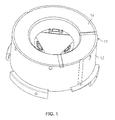
- FIG 1 is an illustration of an assembled inertial measurement unit (IMU).
- IMU inertial measurement unit
- Figure 2 is an illustration of a gyroscope, accelerometer, and support electronics subassembly of the IMU of Figure 1.
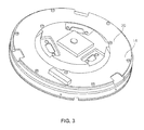
- Figure 3 is an illustration of a power supply subassembly of the IMU of Figure 1.
- FIG. 4 is a block diagram of the IMU of Figure 1, depicting boundaries between the subassemblies of Figures 2 and 3.
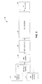
- Figure 5 is a flow diagram illustrating build and rework processes associated with the IMU of Figure 1.
- Figure 6 is an illustration of an assembled IMU having segregated sensor and support electronics subassemblies.
- Figure 7 is an illustration of a gyroscope and accelerometer subassembly of the IMU of Figure 6.
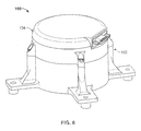
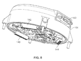
- Figure 8 is an illustration of a support electronics subassembly of the IMU of Figure 6.
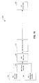
- FIG 9 is a block diagram of the IMU of Figure 6, depicting boundaries between the subassemblies of Figures 7 and 8.
- Figure 10 is a flow diagram illustrating build and rework processes associated with the IMU of Figure 6.
- FIG 1 is an illustration of a known assembled inertial measurement unit (IMU) 10.
- IMU 10 includes both a gyroscope, accelerometer, and support electronics subassembly 12 and a power supply subassembly 14.
- FIG. 2 is an illustration of gyroscope, accelerometer, and support electronics subassembly 12 of IMU 10.
- gyroscope, accelerometer, and support electronics subassembly 12 includes multiple electronic components 20 mounted on a circuit board 22 which are hard wired to the gyroscopes and accelerometers which are mounted beneath circuit board 22.
- a plurality of connectors 24 are also mounted on circuit board 22 which provide an interface to external power sources and further provide an interface to external systems that receive the inertial data that is output from IMU 10. Additionally, connectors 24 also provide an interface for reprogramming and calibration of a processing device which is also mounted on circuit board 22.
- Figure 3 is an illustration of power supply subassembly 14 of IMU 10 of Figure 1. Referring again to Figure 1, it is apparent that Figure 3 illustrates an underside 30 of power supply subassembly 14, and that power supply subassembly 14 includes openings 32 that allow power supply subassembly 14 to be placed onto gyroscope, accelerometer, and support electronics subassembly 12. In this configuration, connectors 24 extend through openings 32 of power supply subassembly 14.
- FIG 4 is a block diagram 50 of IMU 10 (shown in Figure 1).
- Block diagram 50 illustrates functional boundaries between gyroscope, accelerometer, and support electronics subassembly 12 and power supply subassembly 14 respectively illustrated in Figures 2 and 3.
- Power supply subassembly 14 include a power supply 52 which receives power from an external source and converts the received power to levels needed for operation of the various components of gyroscope, accelerometer, and support electronics subassembly 12.
- Gyroscope, accelerometer, and support electronics subassembly 12 includes three gyroscopes 60, associated with the three axes, X, Y, and Z, and three accelerometers 62, also associated with the three axes.
- Outputs from gyroscopes 60 and accelerometers 62 are typically amplified utilizing respective gain components 64 and 66 whose outputs are input into A/D converter 68.
- An output of A/D converter 68 is then provided to a processing device 70, which is programmed to output data to external systems that is representative of the inertial conditions experienced by gyroscopes 60 and accelerometers 62.
- gyroscope, accelerometer, and support electronics subassembly 12 is illustrated as having the five major components described above, those skilled in the art will realize that many additional electronic components are utilized in the fabrication of gyroscope, accelerometer, and support electronics subassembly 12. Typical examples of such electronic components include protective devices that counteract any electrostatic voltages that may become present on the individual connector contacts, logic for allocating A/D converter 68 among the three gyroscopes 60 and accelerometers 62, support components for processing device 70, and the like.
- FIG. 5 is a flow diagram 80 illustrating build and rework processes associated with IMU 10.
- Processes include an electronics assembly process 82, a mechanical assembly process 84, and a sensor assembly process 86.
- An IMU integration process 88 is indicative of the fabrication of the IMU 10, and specifically, fabrication of gyroscope, accelerometer, and support electronics subassembly 12 and power supply subassembly 14 based on the electronics assembly process 82, the mechanical assembly process 84, and the sensor assembly process 86.
- IMU integration process 88 is further indicative of the fabrication of the IMU 10 from the completed gyroscope, accelerometer, and support electronics subassembly 12 and power supply subassembly 14.
- An IMU environmental process 90 is performed to ensure that the completed IMU 10 is able to withstand the rigorous environment to which it will be exposed during its operation.
- An IMU calibration process 92 is performed to characterize the gyroscopes 60 and accelerometers 62, such that the data contained within the outputs received from gyroscope, accelerometer, and support electronics subassembly 12 are as expected. As is known, there are variations between individual gyroscopes 60 and accelerometers 62 due to their mechanical nature, and as represented by the flow diagram 80 of Figure 5, the IMU calibration process 92 is the most time consuming of all the processes utilized to build and/or rework an IMU 10. Upon completion of the IMU calibration process 92, the IMU 10 is accepted for use within a vehicle or other application through an IMU acceptance process 94.
- IMU calibration process 92 is the most time consuming, and likely most expensive, especially when associated with rework of an IMU 10.
- FIG. 6 is an illustration of an assembled IMU 100 having segregated sensor and support electronics subassemblies.
- IMU 100 includes a gyroscope and accelerometer subassembly 102 and a support electronics subassembly 104,
- the segregation of components and packaging may allow, at least for a portion of reworked IMUs 100, that calibration processes, for example, similar to the above described IMU calibration process, need not be repeated for certain repairs and rework of IMUs 100
- FIG. 7 is an illustration of a gyroscope and accelerometer subassembly 102 of IMU 100.
- Gyroscope and accelerometer subassembly 102 includes three gyroscopes 110, 112, and 114, as well as three accelerometers 120, which are housed within a single package.
- a plurality of connectors 130, 132, and 134 are utilized to provide power to gyroscopes 110, 112, and 114 and accelerometers 120.
- Connectors 130, 132, and 134 are further configured to conduct the signals originating from gyroscopes 110, 112, and 114, and accelerometers 120 for further processing before being output from IMU 100 as further described below.
- FIG 8 is an illustration of support electronics subassembly 104 of IMU 100.
- support electronics subassembly 104 includes three connectors 140, 142, and 144 which are configured to mate with connectors 130, 132, and 134 (shown in Figure 7) effectively interconnecting gyroscopes 110, 112, and 114, and accelerometers 120 with their support electronics, which is described below with respect to Figure 9.
- Figure 9 is a block diagram 170 of the IMU of Figure 6, depicting boundaries between the subassemblies 102 and 104 which are respectively shown in Figures 7 and 8. More specifically, block diagram 170 illustrates functional boundaries between gyroscope and accelerometer subassembly 102 and support electronics subassembly 104.
- Support electronics subassembly 104 includes a power supply 180 which receives power from an external source and converts the received power to levels needed for operation of the various components of gyroscope and accelerometer subassembly 102 and support electronics subassembly 104.
- Support electronics subassembly 104 further includes gain components 182 and 184 that receive and amplify outputs from gyroscopes 110, 112, and 114 and accelerometers 120. Outputs of gain components 182 and 184 are then input into A/D converter 186. An output of A/D converter 186 is then provided to a processing device 188, which is programmed to output data to external systems that is representative of the inertial conditions experienced by gyroscopes 110, 112, and 114 and accelerometers 120.
- Gyroscope and accelerometer subassembly 102 as described herein includes three gyroscopes 110, 112, and 114, associated with the three axes, X, Y, and Z, and three accelerometers 120, also associated with the three axes. Output from these sensor devices are respectively input into gain components 182 and 184 (e.g., amplifiers), respectively, as described above.
- gain components 182 and 184 e.g., amplifiers
- support electronics subassembly 104 is illustrated as having power supply 180, gain components 182 and 184, A/D converter 186, and processing device 188, those skilled in the art will realize that many additional electronic components are utilized within support electronics subassembly 104, and that each of the above listed components is fabricated using a number of distinct electronic components. Typical examples of such additional electronic components are described hereinabove, and such examples should not be construed as limiting.
- FIG 10 is a flow diagram 200 illustrating improved rework processes that are associated with IMU 100 of Figures 6-9.
- the processes include an electronics assembly process 202, a mechanical assembly process 204, and a sensor assembly process 206.
- An IMU integration process 208 is indicative of the fabrication of the IMU 100, and specifically, fabrication of gyroscope and accelerometer subassembly 102 and support electronics subassembly 104 based on the electronics assembly process 202, the mechanical assembly process 204, and the sensor assembly process 206.
- IMU integration process 208 is further indicative of the fabrication of the IMU 100 from the completed gyroscope and accelerometer subassembly 102, and support electronics subassembly 104.
- An IMU environmental process 210 is performed to ensure that the completed IMU 100 is able to withstand the rigorous environment to which it will be exposed during its operation. Finally, upon completion of the IMU environmental process 210, the IMU 100 is accepted for use within a vehicle or other application through an IMU acceptance process 212.
- IMU 10 there is no time consuming and expensive IMU calibration process as there is with IMU 10.
- the gyroscopes and accelerometers are separate from the support electronics, there is no disturbance of these devices as a support electronics subassembly 104 is removed and/or replaced during a repair.
- providing an IMU with segregated housing portions for sensors and support electronics, such as IMU 100 eliminates or reduces the amount of time for sensor calibration, at least as compared to known IMUs, after a repair or removal process.
- the housing portions are segregated, repair and replacement of the support electronics subassemblies to not affect orientations or calibrations of the gyroscopes and accelerometers in the other subassembly.
- IMUs that have commingled sensors and support electronics are more likely to have to calibrate their sensors after a repair or replacement of a portion of the support electronics.
Landscapes
- Physics & Mathematics (AREA)
- General Physics & Mathematics (AREA)
- Engineering & Computer Science (AREA)
- Radar, Positioning & Navigation (AREA)
- Remote Sensing (AREA)
- Gyroscopes (AREA)
- Pressure Sensors (AREA)
Applications Claiming Priority (1)
| Application Number | Priority Date | Filing Date | Title |
|---|---|---|---|
| US11/427,937 US7661312B2 (en) | 2006-06-30 | 2006-06-30 | Methods and systems for segregating sensors within a housing |
Publications (2)
| Publication Number | Publication Date |
|---|---|
| EP1873492A2 true EP1873492A2 (fr) | 2008-01-02 |
| EP1873492A3 EP1873492A3 (fr) | 2009-03-25 |
Family
ID=38608809
Family Applications (1)
| Application Number | Title | Priority Date | Filing Date |
|---|---|---|---|
| EP07105253A Withdrawn EP1873492A3 (fr) | 2006-06-30 | 2007-03-29 | Procédé et système pour séparer des capteurs dans un boîtier |
Country Status (3)
| Country | Link |
|---|---|
| US (1) | US7661312B2 (fr) |
| EP (1) | EP1873492A3 (fr) |
| JP (1) | JP2008014928A (fr) |
Families Citing this family (2)
| Publication number | Priority date | Publication date | Assignee | Title |
|---|---|---|---|---|
| US9043055B2 (en) * | 2012-09-07 | 2015-05-26 | Ge Aviation Systems Llc | Method of determining a turbulent condition in an aircraft |
| US9587943B2 (en) * | 2014-10-04 | 2017-03-07 | Honeywell International Inc. | High rate rotation sensing |
Citations (2)
| Publication number | Priority date | Publication date | Assignee | Title |
|---|---|---|---|---|
| US4620442A (en) | 1984-06-14 | 1986-11-04 | Sundstrand Data Control, Inc. | Digital accelerometer |
| EP0908363A2 (fr) | 1997-10-06 | 1999-04-14 | Kabushiki Kaisha Toyoda Jidoshokki Seisakusho | Support de capteur pour véhicule |
Family Cites Families (20)
| Publication number | Priority date | Publication date | Assignee | Title |
|---|---|---|---|---|
| US4336718A (en) | 1980-09-08 | 1982-06-29 | Lear Siegler, Inc. | Control circuit for accelerometer |
| US4975084A (en) * | 1988-10-17 | 1990-12-04 | Amp Incorporated | Electrical connector system |
| US5136998A (en) | 1990-02-06 | 1992-08-11 | Motorola, Inc. | Automotive control unit with internal sensor |
| US5085079A (en) * | 1990-06-11 | 1992-02-04 | Sundstrand Data Control, Inc. | Accelerometer with mounting/coupling structure for an electronics assembly |
| US6295870B1 (en) | 1991-02-08 | 2001-10-02 | Alliedsignal Inc. | Triaxial angular rate and acceleration sensor |
| US5345823A (en) | 1991-11-12 | 1994-09-13 | Texas Instruments Incorporated | Accelerometer |
| US5495414A (en) * | 1993-04-07 | 1996-02-27 | Ford Motor Company | Integrated silicon automotive accelerometer and single-point impact sensor |
| US5442560A (en) | 1993-07-29 | 1995-08-15 | Honeywell, Inc. | Integrated guidance system and method for providing guidance to a projectile on a trajectory |
| US5745347A (en) | 1996-10-11 | 1998-04-28 | Osram Sylvania Inc. | Adapter for connecting airbag accelerometer to a printed circuit board and assembly thereof |
| US6578420B1 (en) | 1997-01-28 | 2003-06-17 | Microsensors, Inc. | Multi-axis micro gyro structure |
| US5918865A (en) | 1997-01-29 | 1999-07-06 | Honeywell Inc. | Load isolator apparatus |
| US5803213A (en) | 1997-02-03 | 1998-09-08 | Honeywell Inc. | Heavy load vibration isolation apparatus |
| US5890569A (en) | 1997-06-06 | 1999-04-06 | Honeywell Inc. | Vibration isolation system for an inertial sensor assembly |
| US5892152A (en) | 1997-07-29 | 1999-04-06 | Litton Systems, Inc. | Multiple vibratory rotation sensors with multiplexed electronics |
| US6498996B1 (en) | 1999-08-04 | 2002-12-24 | Honeywell International Inc. | Vibration compensation for sensors |
| US6578682B2 (en) | 2001-04-26 | 2003-06-17 | Honeywell International Inc. | Compact vibration isolation system for an inertial sensor assembly |
| US6474160B1 (en) | 2001-05-24 | 2002-11-05 | Northrop Grumman Corporation | Counterbalanced silicon tuned multiple accelerometer-gyro |
| JP2003004450A (ja) | 2001-06-25 | 2003-01-08 | Matsushita Electric Ind Co Ltd | 角速度および加速度検出用複合センサ |
| US6778924B2 (en) | 2001-11-06 | 2004-08-17 | Honeywell International Inc. | Self-calibrating inertial measurement system method and apparatus |
| US7181968B2 (en) * | 2004-08-25 | 2007-02-27 | Autoliv Asp, Inc. | Configurable accelerometer assembly |
-
2006
- 2006-06-30 US US11/427,937 patent/US7661312B2/en not_active Expired - Fee Related
-
2007
- 2007-03-29 EP EP07105253A patent/EP1873492A3/fr not_active Withdrawn
- 2007-03-30 JP JP2007091508A patent/JP2008014928A/ja not_active Withdrawn
Patent Citations (2)
| Publication number | Priority date | Publication date | Assignee | Title |
|---|---|---|---|---|
| US4620442A (en) | 1984-06-14 | 1986-11-04 | Sundstrand Data Control, Inc. | Digital accelerometer |
| EP0908363A2 (fr) | 1997-10-06 | 1999-04-14 | Kabushiki Kaisha Toyoda Jidoshokki Seisakusho | Support de capteur pour véhicule |
Also Published As
| Publication number | Publication date |
|---|---|
| EP1873492A3 (fr) | 2009-03-25 |
| US7661312B2 (en) | 2010-02-16 |
| JP2008014928A (ja) | 2008-01-24 |
| US20080000294A1 (en) | 2008-01-03 |
Similar Documents
| Publication | Publication Date | Title |
|---|---|---|
| US6778924B2 (en) | Self-calibrating inertial measurement system method and apparatus | |
| JP5043358B2 (ja) | 傾斜角演算方法及び傾斜角演算装置 | |
| EP3585724B1 (fr) | Suite de capteurs à base de mems | |
| US20140190265A1 (en) | Accommodation of different type of sensors in vibration monitoring system using external input or daughter board wtih interchangeable operating hardware | |
| EP2034321A3 (fr) | Boitier de capteur à axes multiples et procédé d'assemblage | |
| JP4751085B2 (ja) | センサの組立方法 | |
| EP1873492A2 (fr) | Procédé et système pour séparer des capteurs dans un boîtier | |
| CN113646642A (zh) | 信号处理装置、惯性传感器、信号处理方法和程序 | |
| Murphy | Choosing the Most Suitable MEMs Accelerometer for Your Application—Part 1 | |
| NO20091612L (no) | Rutingsanlegg for en undersjoisk elektronisk modul | |
| JP2014032488A (ja) | 制御装置の出荷検査方法 | |
| US6400044B1 (en) | Protective arrangement for electronic functional units and/or functional groups | |
| KR20110050579A (ko) | 단일 패키지에 집적된 경사 보상 나침반 | |
| JP2009053164A (ja) | 物理量センサ | |
| JP7534380B2 (ja) | 方位及び姿勢補正方法、及び方位及び姿勢補正システム | |
| US20070233421A1 (en) | Pressure transducer | |
| EP1337043A2 (fr) | Détection de défaillance d'une fonction de conversion analogique-numérique dans un micro-ordinateur | |
| JP4661750B2 (ja) | Ecu機能検査装置 | |
| JP2011121545A (ja) | 車載制御装置 | |
| WO2003069487A3 (fr) | Bus de donnees pour la commande electrique en cas de construction modulaire | |
| US20240302406A1 (en) | Method and device for processing sensor signals of a sensor unit for a vehicle and sensor system for a vehicle | |
| KR20160141970A (ko) | 아날로그 출력 모듈의 출력 조절 장치 | |
| US7511525B2 (en) | Boundary-scan system architecture for remote environmental testing | |
| US20240201246A1 (en) | Method for checking a signal path of an electronic sensor circuit for a field device in automation technology | |
| EP4257947B1 (fr) | Transducteur de vibrations à capteurs de calibration simplifiés pour la surveillance d'une structure statique ou vibrante |
Legal Events
| Date | Code | Title | Description |
|---|---|---|---|
| PUAI | Public reference made under article 153(3) epc to a published international application that has entered the european phase |
Free format text: ORIGINAL CODE: 0009012 |
|
| AK | Designated contracting states |
Kind code of ref document: A2 Designated state(s): AT BE BG CH CY CZ DE DK EE ES FI FR GB GR HU IE IS IT LI LT LU LV MC MT NL PL PT RO SE SI SK TR |
|
| AX | Request for extension of the european patent |
Extension state: AL BA HR MK YU |
|
| PUAL | Search report despatched |
Free format text: ORIGINAL CODE: 0009013 |
|
| AK | Designated contracting states |
Kind code of ref document: A3 Designated state(s): AT BE BG CH CY CZ DE DK EE ES FI FR GB GR HU IE IS IT LI LT LU LV MC MT NL PL PT RO SE SI SK TR |
|
| AX | Request for extension of the european patent |
Extension state: AL BA HR MK RS |
|
| RIC1 | Information provided on ipc code assigned before grant |
Ipc: G01P 15/00 20060101ALI20090219BHEP Ipc: G01C 19/00 20060101ALI20090219BHEP Ipc: G01P 1/02 20060101AFI20090219BHEP |
|
| 17P | Request for examination filed |
Effective date: 20090914 |
|
| 17Q | First examination report despatched |
Effective date: 20091021 |
|
| AKX | Designation fees paid |
Designated state(s): DE FR GB |
|
| STAA | Information on the status of an ep patent application or granted ep patent |
Free format text: STATUS: THE APPLICATION HAS BEEN WITHDRAWN |
|
| 18W | Application withdrawn |
Effective date: 20110926 |