EP1873511A2 - Arrangement d'un filtre de particules et un capteur pour la détermination des concentrations de particules conductrices dans des gaz - Google Patents
Arrangement d'un filtre de particules et un capteur pour la détermination des concentrations de particules conductrices dans des gaz Download PDFInfo
- Publication number
- EP1873511A2 EP1873511A2 EP07107150A EP07107150A EP1873511A2 EP 1873511 A2 EP1873511 A2 EP 1873511A2 EP 07107150 A EP07107150 A EP 07107150A EP 07107150 A EP07107150 A EP 07107150A EP 1873511 A2 EP1873511 A2 EP 1873511A2
- Authority
- EP
- European Patent Office
- Prior art keywords
- sensor
- electrodes
- filter
- particle
- conductive particles
- Prior art date
- Legal status (The legal status is an assumption and is not a legal conclusion. Google has not performed a legal analysis and makes no representation as to the accuracy of the status listed.)
- Withdrawn
Links
Images


Classifications
-
- G—PHYSICS
- G01—MEASURING; TESTING
- G01N—INVESTIGATING OR ANALYSING MATERIALS BY DETERMINING THEIR CHEMICAL OR PHYSICAL PROPERTIES
- G01N15/00—Investigating characteristics of particles; Investigating permeability, pore-volume or surface-area of porous materials
- G01N15/06—Investigating concentration of particle suspensions
- G01N15/0656—Investigating concentration of particle suspensions using electric, e.g. electrostatic methods or magnetic methods
-
- F—MECHANICAL ENGINEERING; LIGHTING; HEATING; WEAPONS; BLASTING
- F01—MACHINES OR ENGINES IN GENERAL; ENGINE PLANTS IN GENERAL; STEAM ENGINES
- F01N—GAS-FLOW SILENCERS OR EXHAUST APPARATUS FOR MACHINES OR ENGINES IN GENERAL; GAS-FLOW SILENCERS OR EXHAUST APPARATUS FOR INTERNAL-COMBUSTION ENGINES
- F01N2560/00—Exhaust systems with means for detecting or measuring exhaust gas components or characteristics
- F01N2560/05—Exhaust systems with means for detecting or measuring exhaust gas components or characteristics the means being a particulate sensor
-
- F—MECHANICAL ENGINEERING; LIGHTING; HEATING; WEAPONS; BLASTING
- F01—MACHINES OR ENGINES IN GENERAL; ENGINE PLANTS IN GENERAL; STEAM ENGINES
- F01N—GAS-FLOW SILENCERS OR EXHAUST APPARATUS FOR MACHINES OR ENGINES IN GENERAL; GAS-FLOW SILENCERS OR EXHAUST APPARATUS FOR INTERNAL-COMBUSTION ENGINES
- F01N2560/00—Exhaust systems with means for detecting or measuring exhaust gas components or characteristics
- F01N2560/12—Other sensor principles, e.g. using electro conductivity of substrate or radio frequency
Definitions
- the present invention relates to an arrangement of a particulate filter for conductive particles in mixed gas streams and a sensor for the resistive determination of concentrations of conductive particles in gases.
- soot particulate filters have been used recently. To monitor the effectiveness of these filters, it is conceivable to use sensors that measure the particulate content of the exhaust gases passing through the filter (on-board diagnostics, OBD).
- OBD on-board diagnostics
- a resistive particle sensor can be used as the sensor type, which uses the resistance or impedance change of an interdigital electrode structure by the addition of (conductive) soot particles from the exhaust gas flow as a measured variable.
- resistive particle sensors are known, in which two or more metallic electrodes are formed, wherein the accumulating particles, in particular soot particles, the comb-like interdigitated electrodes short and so with increasing particle concentration on the sensor surface, a decreasing resistance or a decreasing Impedance (or an increasing current at constant applied voltage) between the electrodes is measurable.
- the measured current or its change can be correlated with the accumulated particle mass and thus also with the prevailing in the exhaust gas particle concentration. If the particle concentration exceeds a certain level, this is a sign that the particle filter is defective.
- the particle sensor emits a signal, due to which the filter is regenerated.
- the filter id R is heated to such an extent via an integrated heating element that the soot particles retained in the filter are burned to carbon dioxide. If the particle concentration does not decrease after regeneration, the filter is probably defective.
- the sensor element For regeneration of the sensor element after particle accumulation, the sensor element must be burned free.
- a specially provided heating element is required, which increases the technical complexity of such a sensor and at the same time makes it susceptible to interference.
- the object of the present invention is to provide an arrangement of a particle filter and a resistive particle sensor which, in contrast to the arrangements known from the prior art, causes a lower production outlay and in particular has a lower susceptibility to interference.
- a particulate filter for conductive particles in mixed gas streams with a heater for thermal regeneration of the particulate filter and a sensor for resistive determination of concentrations of conductive particles in gases, which is arranged downstream of the particulate filter in the mixed gas stream, is provided.
- the sensor has a surface exposed to the mixed gas mixture with at least two electrodes which are arranged at a distance from each other on the surface, in such a way that conductive particles from the mixed gas stream are deposited on the surface of the sensor, the distance between the electrodes bridge over and establish in this way a conductive connection between the electrodes of the sensor, from which a measure of the concentration of the conductive particles in the gas mixture can be derived.
- the arrangement of particle filter and resistive sensor is characterized in that both are arranged to each other so that the heater for thermal regeneration of the particulate filter is also used for thermal regeneration of the sensor. This means that a separate heating device for the sensor is dispensable.
- Thermal regeneration means that the conductive particles collected by the particle filter from the gas mixture, in particular soot particles, are burnt by heating the filter to carbon dioxide, the latter escaping as gas from the filter. In this way, the filter is emptied of residues and regenerated so.
- the type of arrangement according to the invention is possible because of an intact particulate filter of the latest design due to the high filter efficiencies, the amount of particles passing through the filter is extremely low, so that with a suitable design of the resistive sensor in the time range between two regeneration cycles of the particulate filter practically exclusively a zero signal supplies and thus indicates the integrity of the particulate filter.
- the present invention discloses a technical teaching, according to which it is possible to dispense with a separate heating element in the sensor.
- the amount of particles passing through the filter between two regeneration cycles is so great that, with a suitable design of the resistive sensor, a current can be measured after a certain time.
- the amount of current or the speed of the current increase or the time duration after full regeneration until reaching a defined signal level can be used as a measure of the still existing filter efficiency.
- the measured variable detected by the resistive sensor can be the time that elapses until a conductive contact between the two electrodes is produced by the attached conductive particles, ie the resistance or the impedance changes from infinite to finite at an applied voltage Value reduced.
- a sensor having a large distance between the two electrodes thus has a lower sensitivity than a sensor having a smaller distance between the two electrodes.
- the absolute value of resistance or impedance which is a reciprocal measure of the amount of deposited soot particles, can also be used as the measured variable.
- the surface of the sensor consists of a non-conductive ceramic material.
- a non-conductive ceramic material e.g. Alumina are used.
- the electrodes are arranged to one another in the form of interdigital electrodes.
- Such types of electrodes mesh with each other in a comb-like manner and keep a constant distance from one another. Soot particles depositing on the surface bridge this distance and, assuming a sufficiently high concentration in the gas, close the electrodes after a certain time.
- the electrodes are applied to the surface of the sensor by means of screen printing technology. This technique makes it possible to reduce the distance between the electrodes to 50 ⁇ m. Even smaller distances between the electrodes can be achieved with photolithographic methods, which are not preferred for cost reasons.
- Other possible methods for applying the electrodes to the surface are e.g. Stencil printing, pad printing, ink jet printing or a transfer film process.
- the conductive particles to be determined are soot particles.
- the sensor is a soot particle sensor, as e.g. used in motor vehicles with a diesel engine.
- the gas mixture is a combustion gas mixture, and the particle filter and sensor are arranged in the exhaust gas flow of the diesel engine.
- the senor has at least two sensor sections each having at least two electrodes, wherein the electrodes of the at least two sensor sections each have different distances and / or configurations, the at least two sensor sections are operated with different voltages or the electrodes of the at least two sensor sections have different materials. In this way, different measuring ranges or measuring sensitivities can be realized at the different sensor sections.
- the senor could be designed such that an intact filter generates a signal neither at one nor at the other sensor section during a regular regeneration cycle, whereas a completely defective filter generates a signal at both sensor sections, and a partially defective filter finally generates a signal at the more sensitive sensor section, but not at the less sensitive sensor section. In this way, it is possible to make very accurate statements about the nature of the filter in real time.
- a method for monitoring the particle concentration in the exhaust stream of an internal combustion engine comprising an arrangement of a particulate filter and a downstream sensor according to one of the preceding claims.
- the method is characterized in that an electrical quantity measured or generated by the sensor is used as a parameter for the efficiency of the particle filter.
- This measurand may be e.g. to act a resistance or an impedance, but also about the current flowing at an applied voltage according to the Ohm's law electric current. Likewise, the time to reach a critical resistance, a critical impedance or a critical electric current can be used as a measured variable.
- the particle quantity passing through the filter is extremely low, so that with a suitable design of the resistive sensor, it supplies only a zero signal in a time interval between two regeneration cycles of the particulate filter, e.g. an infinitely high resistance or an infinitely high impedance or a non-measurable current, and thus indicates the integrity of the particulate filter.
- FIG. 1 shows a sensor 10 according to the invention with a paired electrode 11, which is arranged on the surface of a carrier material 12. Between the electrode and the carrier material, one or more insulating layers 13 are further arranged, e.g. can consist of a non-conductive paint.
- FIG. 2 shows the sensor signal, in the present case the current resulting from an applied voltage due to the resistance between the two electrodes, for an intact (FIG. 2A) and two partially defective particle filters with different efficiencies (FIG. 2B: 70%, FIG. 2C : 50%).
- FIG. 2A the current resulting from an applied voltage due to the resistance between the two electrodes
- FIG. 2B the current resulting from an applied voltage due to the resistance between the two electrodes
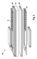
- FIG. 3 shows a sensor 30 according to the invention with two sensor sections 31, 32 on the front and rear sides of a ceramic element 33.
- the two sensor sections have different measuring sensitivities, which may be e.g. is accomplished by different electrode distances, versions, or measuring voltages.
- one or more insulating layers 34 e.g. can consist of a non-conductive paint.
- the sensor section 32 has a different electrode spacing than the sensor section 31.
- a comparison between two different sensitivities can be made, which can facilitate the evaluation of the signals.
- the measuring cells can be designed such that the first sensor section 31 already delivers a signal, while the second sensor section 32 does not yet supply a signal due to the lower sensitivity.
- a completely defective filter would then be defined by a signal on both measuring cells, while an intact filter in both measuring cells would not provide a signal.
Landscapes
- Chemical & Material Sciences (AREA)
- Dispersion Chemistry (AREA)
- Physics & Mathematics (AREA)
- Health & Medical Sciences (AREA)
- Life Sciences & Earth Sciences (AREA)
- Analytical Chemistry (AREA)
- Biochemistry (AREA)
- General Health & Medical Sciences (AREA)
- General Physics & Mathematics (AREA)
- Immunology (AREA)
- Pathology (AREA)
- Investigating Or Analyzing Materials By The Use Of Electric Means (AREA)
Applications Claiming Priority (1)
| Application Number | Priority Date | Filing Date | Title |
|---|---|---|---|
| DE200610029214 DE102006029214A1 (de) | 2006-06-26 | 2006-06-26 | Anordnung aus einem Partikelfilter und einem Sensor zur resistiven Bestimmung von Konzentrationen leitfähiger Partikel in Gasen |
Publications (2)
| Publication Number | Publication Date |
|---|---|
| EP1873511A2 true EP1873511A2 (fr) | 2008-01-02 |
| EP1873511A3 EP1873511A3 (fr) | 2008-07-16 |
Family
ID=38235015
Family Applications (1)
| Application Number | Title | Priority Date | Filing Date |
|---|---|---|---|
| EP07107150A Withdrawn EP1873511A3 (fr) | 2006-06-26 | 2007-04-27 | Arrangement d'un filtre de particules et un capteur pour la détermination des concentrations de particules conductrices dans des gaz |
Country Status (2)
| Country | Link |
|---|---|
| EP (1) | EP1873511A3 (fr) |
| DE (1) | DE102006029214A1 (fr) |
Cited By (3)
| Publication number | Priority date | Publication date | Assignee | Title |
|---|---|---|---|---|
| CN102606266A (zh) * | 2011-01-20 | 2012-07-25 | 福特环球技术公司 | 用于确定排气中的微粒的微粒传感器、排气系统和方法 |
| DE102011002937A1 (de) | 2011-01-20 | 2012-07-26 | Ford Global Technologies, Llc | Partikelsensor, Abgassystem und Verfahren zum Bestimmen von Partikeln im Abgas |
| DE102013206092A1 (de) * | 2013-04-05 | 2014-10-09 | Continental Automotive Gmbh | Verfahren zur Auswertung der Messwerte eines Rußsensors |
Families Citing this family (2)
| Publication number | Priority date | Publication date | Assignee | Title |
|---|---|---|---|---|
| DE102007039566A1 (de) * | 2007-08-22 | 2009-02-26 | Robert Bosch Gmbh | Sensorelement und Verfahren zur Detektion von Teilchen in einem Gasstrom sowie deren Verwendung |
| DE102009051507A1 (de) * | 2009-10-30 | 2011-05-05 | Continental Automotive Gmbh | Rußsensor |
Citations (2)
| Publication number | Priority date | Publication date | Assignee | Title |
|---|---|---|---|---|
| WO2005124313A1 (fr) * | 2004-06-16 | 2005-12-29 | Robert Bosch Gmbh | Procede pour influer sur le depot de suie sur des capteurs |
| DE102006040351A1 (de) * | 2006-08-29 | 2008-03-06 | Robert Bosch Gmbh | Sensor zur resistiven Bestimmung von Konzentrationen leitfähiger Partikel in Gasgemischen |
Family Cites Families (8)
| Publication number | Priority date | Publication date | Assignee | Title |
|---|---|---|---|---|
| JPS5939915A (ja) * | 1982-08-27 | 1984-03-05 | Mazda Motor Corp | ディ−ゼルエンジンの排気ガス浄化装置 |
| DE3608801A1 (de) * | 1986-03-15 | 1987-09-17 | Fev Forsch Energietech Verbr | Verfahren und vorrichtung zur regeneration von partikelfiltersystemen |
| AU9146191A (en) * | 1991-10-25 | 1993-05-21 | Caterpillar Inc. | Method and apparatus for initiating regeneration in an engine exhaust particulate filter |
| DE10102491C2 (de) * | 2001-01-19 | 2003-04-17 | Walter Hofmann | Verfahren zum Betrieb einer Vorrichtung im Abgassystem eines Verbrennungsmotors zur Prüfung der Belastung des Abgasstroms mit Rußpartikeln, sowie diese Vorrichtung |
| US6634210B1 (en) * | 2002-04-17 | 2003-10-21 | Delphi Technologies, Inc. | Particulate sensor system |
| DE502005003454D1 (de) * | 2004-02-12 | 2008-05-08 | Daimler Ag | Vorrichtung zur feststellung des zustands eines russpartikelfilters |
| DE102004007039A1 (de) * | 2004-02-12 | 2005-09-01 | Daimlerchrysler Ag | Vorrichtung und Verfahren zur Ermittlung des Beladungszustands eines Partikelfilters |
| DE102005033025A1 (de) * | 2005-07-15 | 2007-01-25 | Daimlerchrysler Ag | Partikelfilter |
-
2006
- 2006-06-26 DE DE200610029214 patent/DE102006029214A1/de not_active Withdrawn
-
2007
- 2007-04-27 EP EP07107150A patent/EP1873511A3/fr not_active Withdrawn
Patent Citations (3)
| Publication number | Priority date | Publication date | Assignee | Title |
|---|---|---|---|---|
| WO2005124313A1 (fr) * | 2004-06-16 | 2005-12-29 | Robert Bosch Gmbh | Procede pour influer sur le depot de suie sur des capteurs |
| DE102004028997A1 (de) * | 2004-06-16 | 2006-01-05 | Robert Bosch Gmbh | Verfahren zur Beeinflussung der Russanlagerung auf Sensoren |
| DE102006040351A1 (de) * | 2006-08-29 | 2008-03-06 | Robert Bosch Gmbh | Sensor zur resistiven Bestimmung von Konzentrationen leitfähiger Partikel in Gasgemischen |
Cited By (6)
| Publication number | Priority date | Publication date | Assignee | Title |
|---|---|---|---|---|
| CN102606266A (zh) * | 2011-01-20 | 2012-07-25 | 福特环球技术公司 | 用于确定排气中的微粒的微粒传感器、排气系统和方法 |
| DE102011002936A1 (de) | 2011-01-20 | 2012-07-26 | Ford Global Technologies, Llc | Partikelsensor, Abgassystem und Verfahren zum Bestimmen von Partikeln im Abgas |
| DE102011002937A1 (de) | 2011-01-20 | 2012-07-26 | Ford Global Technologies, Llc | Partikelsensor, Abgassystem und Verfahren zum Bestimmen von Partikeln im Abgas |
| US9052259B2 (en) | 2011-01-20 | 2015-06-09 | Ford Global Technologies, Llc | Particle sensor, exhaust system and method for determining particles in the exhaust gas |
| US9874509B2 (en) | 2011-01-20 | 2018-01-23 | Ford Global Technologies, Llc | Particle sensor, exhaust system and method for determining particles in the exhaust gas |
| DE102013206092A1 (de) * | 2013-04-05 | 2014-10-09 | Continental Automotive Gmbh | Verfahren zur Auswertung der Messwerte eines Rußsensors |
Also Published As
| Publication number | Publication date |
|---|---|
| EP1873511A3 (fr) | 2008-07-16 |
| DE102006029214A1 (de) | 2007-12-27 |
Similar Documents
| Publication | Publication Date | Title |
|---|---|---|
| DE112010005888B4 (de) | Feinstaub-Erfassungsvorrichtung für Verbrennungsmaschinen | |
| DE10011562C2 (de) | Gassensor | |
| DE102009028283B4 (de) | Verfahren und Vorrichtung zur Eigendiagnose eines Partikelsensors | |
| DE112011104817B4 (de) | Controller einer Verbrennungsmaschine | |
| EP2130025A2 (fr) | Élément détecteur d'un capteur de gaz | |
| EP2391878B1 (fr) | Procédé et dispositif pour mesurer la charge en suies dans des systèmes d'échappement de moteurs diesel | |
| WO2009043711A1 (fr) | Procédé d'autodiagnostic d'un détecteur de particules, détecteurs de particules aptes à la réalisation du procédé et leur utilisation | |
| WO2012085035A1 (fr) | Procédé de fonctionnement d'un capteur de suie | |
| DE112017006342T5 (de) | Vorrichtung zur Detektion von Feinstaub | |
| WO2008025602A1 (fr) | Capteur servant à déterminer de manière résistive des concentrations de particules conductrices dans des mélanges gazeux | |
| EP1761760A1 (fr) | Procede, capteur de particules, et systeme de detection de particules pour mesurer des particules | |
| EP1873511A2 (fr) | Arrangement d'un filtre de particules et un capteur pour la détermination des concentrations de particules conductrices dans des gaz | |
| DE112018000537T5 (de) | Partikelzähler | |
| EP2901134A1 (fr) | Capteur de détection de particules | |
| DE102017116173A1 (de) | Verfahren und system zum erfassen von feinstaub in abgas | |
| EP2035785A1 (fr) | Dispositif de mesure pour la mesure du débit d'un mélange de gazde combustion, comportant un dispositif de correction | |
| DE102011083339A1 (de) | Partikelerfassungssensor | |
| WO2006103272A1 (fr) | Element de capteur destine a des capteurs a particules et procede d'utilisation | |
| DE102019115156A1 (de) | Abgasfeinstaubsensor | |
| EP2145173A1 (fr) | Détecteur permettant de détecter des particules dans un courant gazeux | |
| DE102009046315A1 (de) | Verfahren und Vorrichtung zum Betreiben eines Partikelsensors | |
| DE102008041809A1 (de) | Partikelsensor, Verfahren zu dessen Betrieb und Herstellung | |
| DE102009000077B4 (de) | Partikelsensor mit Referenzmesszelle und Verfahren zur Detektion von leitfähigen Partikeln | |
| DE112015005740T5 (de) | Feinstaub-Erfassungselement | |
| DE102007046097A1 (de) | Sensorelement und Sensor mit Eigendiagnosefunktion zur Detektion von Teilchen in einem Gasstrom |
Legal Events
| Date | Code | Title | Description |
|---|---|---|---|
| PUAI | Public reference made under article 153(3) epc to a published international application that has entered the european phase |
Free format text: ORIGINAL CODE: 0009012 |
|
| AK | Designated contracting states |
Kind code of ref document: A2 Designated state(s): AT BE BG CH CY CZ DE DK EE ES FI FR GB GR HU IE IS IT LI LT LU LV MC MT NL PL PT RO SE SI SK TR |
|
| AX | Request for extension of the european patent |
Extension state: AL BA HR MK YU |
|
| PUAL | Search report despatched |
Free format text: ORIGINAL CODE: 0009013 |
|
| AK | Designated contracting states |
Kind code of ref document: A3 Designated state(s): AT BE BG CH CY CZ DE DK EE ES FI FR GB GR HU IE IS IT LI LT LU LV MC MT NL PL PT RO SE SI SK TR |
|
| AX | Request for extension of the european patent |
Extension state: AL BA HR MK RS |
|
| RIC1 | Information provided on ipc code assigned before grant |
Ipc: F01N 3/023 20060101ALI20080606BHEP Ipc: G01N 27/12 20060101ALI20080606BHEP Ipc: G01N 15/06 20060101AFI20070719BHEP |
|
| 17P | Request for examination filed |
Effective date: 20090116 |
|
| AKX | Designation fees paid |
Designated state(s): AT BE BG CH CY CZ DE DK EE ES FI FR GB GR HU IE IS IT LI LT LU LV MC MT NL PL PT RO SE SI SK TR |
|
| 17Q | First examination report despatched |
Effective date: 20090311 |
|
| STAA | Information on the status of an ep patent application or granted ep patent |
Free format text: STATUS: THE APPLICATION IS DEEMED TO BE WITHDRAWN |
|
| 18D | Application deemed to be withdrawn |
Effective date: 20111102 |