EP1873534A2 - Vorrichtung zur berührungsfreien Erfassung der Drehzahl und/oder Position eines Geberteils mit einem Encoder - Google Patents
Vorrichtung zur berührungsfreien Erfassung der Drehzahl und/oder Position eines Geberteils mit einem Encoder Download PDFInfo
- Publication number
- EP1873534A2 EP1873534A2 EP07012623A EP07012623A EP1873534A2 EP 1873534 A2 EP1873534 A2 EP 1873534A2 EP 07012623 A EP07012623 A EP 07012623A EP 07012623 A EP07012623 A EP 07012623A EP 1873534 A2 EP1873534 A2 EP 1873534A2
- Authority
- EP
- European Patent Office
- Prior art keywords
- encoder
- pole
- poles
- track
- sensor
- Prior art date
- Legal status (The legal status is an assumption and is not a legal conclusion. Google has not performed a legal analysis and makes no representation as to the accuracy of the status listed.)
- Granted
Links
Images
Classifications
-
- G—PHYSICS
- G01—MEASURING; TESTING
- G01P—MEASURING LINEAR OR ANGULAR SPEED, ACCELERATION, DECELERATION, OR SHOCK; INDICATING PRESENCE, ABSENCE, OR DIRECTION, OF MOVEMENT
- G01P3/00—Measuring linear or angular speed; Measuring differences of linear or angular speeds
- G01P3/42—Devices characterised by the use of electric or magnetic means
- G01P3/44—Devices characterised by the use of electric or magnetic means for measuring angular speed
- G01P3/48—Devices characterised by the use of electric or magnetic means for measuring angular speed by measuring frequency of generated current or voltage
- G01P3/481—Devices characterised by the use of electric or magnetic means for measuring angular speed by measuring frequency of generated current or voltage of pulse signals
- G01P3/487—Devices characterised by the use of electric or magnetic means for measuring angular speed by measuring frequency of generated current or voltage of pulse signals delivered by rotating magnets
-
- G—PHYSICS
- G01—MEASURING; TESTING
- G01D—MEASURING NOT SPECIALLY ADAPTED FOR A SPECIFIC VARIABLE; ARRANGEMENTS FOR MEASURING TWO OR MORE VARIABLES NOT COVERED IN A SINGLE OTHER SUBCLASS; TARIFF METERING APPARATUS; MEASURING OR TESTING NOT OTHERWISE PROVIDED FOR
- G01D5/00—Mechanical means for transferring the output of a sensing member; Means for converting the output of a sensing member to another variable where the form or nature of the sensing member does not constrain the means for converting; Transducers not specially adapted for a specific variable
- G01D5/12—Mechanical means for transferring the output of a sensing member; Means for converting the output of a sensing member to another variable where the form or nature of the sensing member does not constrain the means for converting; Transducers not specially adapted for a specific variable using electric or magnetic means
- G01D5/14—Mechanical means for transferring the output of a sensing member; Means for converting the output of a sensing member to another variable where the form or nature of the sensing member does not constrain the means for converting; Transducers not specially adapted for a specific variable using electric or magnetic means influencing the magnitude of a current or voltage
- G01D5/142—Mechanical means for transferring the output of a sensing member; Means for converting the output of a sensing member to another variable where the form or nature of the sensing member does not constrain the means for converting; Transducers not specially adapted for a specific variable using electric or magnetic means influencing the magnitude of a current or voltage using Hall-effect devices
- G01D5/145—Mechanical means for transferring the output of a sensing member; Means for converting the output of a sensing member to another variable where the form or nature of the sensing member does not constrain the means for converting; Transducers not specially adapted for a specific variable using electric or magnetic means influencing the magnitude of a current or voltage using Hall-effect devices influenced by the relative movement between the Hall device and magnetic fields
-
- G—PHYSICS
- G01—MEASURING; TESTING
- G01D—MEASURING NOT SPECIALLY ADAPTED FOR A SPECIFIC VARIABLE; ARRANGEMENTS FOR MEASURING TWO OR MORE VARIABLES NOT COVERED IN A SINGLE OTHER SUBCLASS; TARIFF METERING APPARATUS; MEASURING OR TESTING NOT OTHERWISE PROVIDED FOR
- G01D5/00—Mechanical means for transferring the output of a sensing member; Means for converting the output of a sensing member to another variable where the form or nature of the sensing member does not constrain the means for converting; Transducers not specially adapted for a specific variable
- G01D5/12—Mechanical means for transferring the output of a sensing member; Means for converting the output of a sensing member to another variable where the form or nature of the sensing member does not constrain the means for converting; Transducers not specially adapted for a specific variable using electric or magnetic means
- G01D5/244—Mechanical means for transferring the output of a sensing member; Means for converting the output of a sensing member to another variable where the form or nature of the sensing member does not constrain the means for converting; Transducers not specially adapted for a specific variable using electric or magnetic means influencing characteristics of pulses or pulse trains; generating pulses or pulse trains
- G01D5/245—Mechanical means for transferring the output of a sensing member; Means for converting the output of a sensing member to another variable where the form or nature of the sensing member does not constrain the means for converting; Transducers not specially adapted for a specific variable using electric or magnetic means influencing characteristics of pulses or pulse trains; generating pulses or pulse trains using a variable number of pulses in a train
- G01D5/2454—Encoders incorporating incremental and absolute signals
- G01D5/2455—Encoders incorporating incremental and absolute signals with incremental and absolute tracks on the same encoder
- G01D5/2457—Incremental encoders having reference marks
-
- F—MECHANICAL ENGINEERING; LIGHTING; HEATING; WEAPONS; BLASTING
- F02—COMBUSTION ENGINES; HOT-GAS OR COMBUSTION-PRODUCT ENGINE PLANTS
- F02D—CONTROLLING COMBUSTION ENGINES
- F02D41/00—Electrical control of supply of combustible mixture or its constituents
- F02D41/009—Electrical control of supply of combustible mixture or its constituents using means for generating position or synchronisation signals
-
- F—MECHANICAL ENGINEERING; LIGHTING; HEATING; WEAPONS; BLASTING
- F02—COMBUSTION ENGINES; HOT-GAS OR COMBUSTION-PRODUCT ENGINE PLANTS
- F02D—CONTROLLING COMBUSTION ENGINES
- F02D41/00—Electrical control of supply of combustible mixture or its constituents
- F02D41/0097—Electrical control of supply of combustible mixture or its constituents using means for generating speed signals
Definitions
- the invention relates to a device for non-contact detection of the rotational speed and / or position of an encoder rotatable about an axis with a permanent magnetic encoder in ring form with circumferentially alternately arranged regular north and south poles and at least one irregular pole and a scanning head with a difference -Hallsensor.
- Devices of this type find a versatile application for determining the speed of a shaft or for detecting the position of the shaft.
- the encoder is mounted on the transmitter part and a scanning head provides corresponding signals from which the speed or position information can be derived.
- the encoder is equipped with alternating regular north and south poles and which is provided a scanning head with a differential Hall sensor.
- the encoder is provided with at least one irregularity in the Pol 72 on its circumference. This irregularity is that a selected pole is made with a larger angular length or radian measure and that this pole is given a special shape with a special magnetization.
- Such an encoder is difficult to manufacture because the geometric shape of the irregular poles is difficult to magnetize. Also, deviations in the mounting of the scanning head with the sensors therein from its axial position lead to errors in the detection of the pitch.
- the invention has for its object to avoid the disadvantages of the previously known devices and to create a device that is easy to manufacture and a reliable determination of the speed or the position the encoder part allowed.
- the incursions of the magnetic field in the middle of wide and very wide poles should have no influence on the correct functionality of the system encoder sensor.
- An accurate angle measurement of the encoder part is to be achieved.
- the device mentioned above is equipped with a Doppelspurencoder with opposite magnetization and assigned each encoder track per a sensor element of the differential Hall sensor.
- a Doppelspurencoder with opposite magnetization and assigned each encoder track per a sensor element of the differential Hall sensor.
- the pitch error in the sensor distance is negligible.
- the radial distance of the sensor from the encoder surface has little influence on the accuracy of the detection of the position of the encoder part.
- the dependence of the sensitivity of the measurement of the pole width is largely avoided. Due to the opposite magnetization of the poles of the individual tracks and the assignment of one sensor element of the differential Hall sensor to a track, two signals are created whose course is assigned to each track and a sensor element and which are aligned opposite in their plus and minus areas.
- At least one of the poles of a track in the circumferential direction is carried out with a larger pole width than the adjacent poles.
- This pole with the greater radians in one lane, is assigned an opposite pole with the same pole width on the other lane.
- the axial track widths of the individual tracks are formed the same size.
- the sensor elements are mounted adjacent to each other axially adjacent.
- the axial distance A between the sensor elements determines how far the sensor encoder system can be moved axially against each other until the function is no longer guaranteed.
- the functional area is limited to half the distance of the sensor elements in both directions.
- the distance A determines from which pole width PB in [°] an independence of the angular position of the pole boundary from the sensor spacing is given solely by physical compensation effects / reasons of symmetry. From a pole width PB> A • 360 ⁇ ° ⁇ D set the compensation effects off PB> 2 • A • 360 ⁇ ° ⁇ D the pole boundary is independent of the sensor distance.
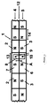
- the surface of an encoder is shown in the figure 1, which is designed as Doppelspurencoder 1, with opposite magnetization of the regular north and south poles 2 and 3.
- the surface of an encoder is shown in the figure 1, which is designed as Doppelspurencoder 1, with opposite magnetization of the regular north and south poles 2 and 3.
- On each encoder track 4 and 5 are a corresponding number of poles 2 and 3 attached.
- the number of poles 2 and 3 is determined by the predetermined pitch angle, which is usually between 3 ° and 12 ° in the regular poles 2 and 3.
- the pole width or the angle length 14 is the same for each regular pole 2 or 3.
- each encoder track 4 and 5 In addition to the regular poles 2 and 3 are on each encoder track 4 and 5 irregular poles 6 and 7, with a larger angular length 13 (pole width) attached, which also have an opposite magnetization to each other.
- the dual track encoder 1 is assigned to the differential Hall sensor 8, in such a way that each track 4, 5, a sensor element 9, 10 is assigned.
- the formation of the encoder with regular poles 2 and 3 and with irregular poles 6 and 7 allows both the detection of the rotational speed of a shaft, as well as the position of the shaft with the attached cams or the like.
- the mutually facing pole widths PB S and PB N of tracks 4 and 5 are the same size.
- the differential reverb 8 is placed in the middle of the middle plane 12 between the tracks 4 and 5.
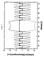
- FIG. 2 is a fragmentary diagram of the curve as it results in the B field of the magnetic flux density in Tesla, depending on the angular position of the Hall sensors 9 and 10. Visible here is the uniformity of the regular poles 2, 3 and the strong deviation in the middle at the irregular poles 6 and 7.
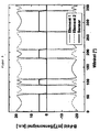
- FIG. 3 shows a diagram of the curve in a device having poles with different pole widths.
- a device is preferably used in camshafts, since here the position detection is in the foreground.
Landscapes
- Physics & Mathematics (AREA)
- General Physics & Mathematics (AREA)
- Transmission And Conversion Of Sensor Element Output (AREA)
Abstract
Description
- Die Erfindung befasst sich mit einer Vorrichtung zur berührungsfreien Erfassung der Drehzahl und/oder Position eines um eine Achse drehbaren Geberteils mit einem permanentmagnetischen Encoder in Ringform mit in Umfangsrichtung abwechselnd angeordneten regulären Nord- und Südpolen und wenigstens einem unregelmäßigen Pol sowie mit einem Abtastkopf mit einem Differenzen-Hallsensor.
- Vorrichtungen dieser Art finden eine vielseitige Anwendung zur Ermittlung der Drehzahl einer Welle oder auch zur Positionserfassung der Welle. Der Encoder ist am Geberteil angebracht und ein Abtastkopf liefert entsprechende Signale aus denen die Drehzahl- oder Positionsinformation abgeleitet werden kann.
- Aus der
US 200310116703 A1 - Eine andere Möglichkeit, insbesondere zur Positionserfassung, zeigt die
EP 0 496 918 A1 . Dort werden in einem Abtastkopf zwei im Abstand voneinander angebrachte Hall-Sensoren verwendet, die ein Sensorsignal abgeben, wenn sie einer Markierung des Geberteils gegenüberstehen. Als Geberteil können zwei gegeneinander verdrehte Zahnräder verwendet werden, wobei jedem Zahn des einen Zahnrads eine Lücke des anderen Zahnrads gegenübersteht. Die mit dieser Vorrichtung erreichbaren Symmetrieeigenschaften sind nicht zufrieden stellend. - Der Erfindung liegt die Aufgabe zugrunde, die Nachteile der bisher bekannten Vorrichtungen zu vermeiden und eine Vorrichtung zu erstellen, die einfach in der Herstellung ist und eine sichere Ermittlung der Drehzahl bzw. der Position des Geberteils erlaubt. Insbesondere sollen die auftretenden Einbrüche des magnetischen Feldes in der Mitte von breiten und sehr breiten Polen keinen Einfluß auf die korrekte Funktionalität des System Encoder-Sensor haben. Eine genaue Winkelmessung des Geberteils soll erreicht werden.
- Die Lösung der gestellten Aufgabe wird mit den Merkmalen des Anspruchs 1 erreicht. Die Unteransprüche 2 bis 8 sind vorteilhafte weitere Ausbildungen des Erfindungsgegenstandes. Um die gestellte Aufgabe erfüllen zu können, wird die eingangs genannte Vorrichtung mit einem Doppelspurencoder mit entgegengesetzter Magnetisierung ausgestattet und jeder Encoderspur je ein Sensorelement des Differenzen-Hallsensors zugeordnet. In Versuchen hat sich gezeigt, dass eine solche Vorrichtung eine hohe Stabilität des Magnetfelds ergibt, und darüber hinaus der Teilungsfehler beim Sensorabstand vernachlässigbar gering ist. Der radiale Abstand des Sensors von der Encoderoberfläche hat kaum Einfluss auf die Genauigkeit der Detektierung der Position des Geberteils. Auch wird die Abhängigkeit der Empfindlichkeit der Messung von der Polbreite weitgehendst vermieden. Durch die entgegengesetzte Magnetisierung der Pole der einzelnen Spuren und die Zuordnung von je einem Sensorelement des Differenzen-Hallsensors zu einer Spur werden zwei Signale erstellt, deren Verlauf je einer Spur und einem Sensorelement zugeordnet ist und die in ihren Plus- und Minusbereichen entgegengesetzt ausgerichtet sind.
- Um eine Positionsmessung vornehmen zu können, wird wenigstens einer der Pole einer Spur in Umfangsrichtung mit einer größeren Polbreite als die angrenzenden Pole ausgeführt. Diesem Pol, mit dem größeren Bogenmaß in der einen Spur, wird ein entgegengesetzter Pol mit der gleichen Polbreite auf der anderen Spur zugeordnet.
- Bevorzugt werden die axialen Spurbreiten der einzelnen Spuren gleich groß ausgebildet. Die Sensorelemente werden axial benachbart nebeneinander angebracht. Der axiale Abstand A zwischen den Sensorelementen bestimmt wie weit das System Sensor-Encoder axial gegeneinander verschoben werden kann, bis die Funktion nicht mehr gewährleistet ist. Der Funktionsbereich ist mit dem halben Abstand der Sensorelemente in beiden Richtungen begrenzt. Darüber hinaus bestimmt der Abstand A, ab welcher Polbreite PB in [°] eine Unabhängigkeit der Winkelposition der Polgrenze vom Sensorabstand allein durch physikalische Kompensationseffekte/Symmetriegründe gegeben ist. Ab einer Polbreite PB >


- Anhand des in der Zeichnung dargestellten Ausführungsbeispiels wird die Erfindung nachstehend näher erläutert.
- Es zeigt:
- Fig. 1
- in schematischer Darstellung einen Doppelspurencoder in der Draufsicht mit einem Differenzen-Hallsensor
- Fig. 2
- einen Ausschnitt des Magnetfeldes, aufgetragen über dem aus der Figur 1 dargestellten Abschnitt des Encoders und
- Fig. 3
- einen Ausschnitt eines Magnetfeldes mit unterschiedlichen Polbreiten.
- Auf die Darstellung der einzelnen Teile der Vorrichtung wird verzichtet, da dieselben an sich bekannt sind und aus der eingangs genannten US-Druckschrift zum Stand der Technik auch zu entnehmen sind. In der Figur 1 ist deshalb im Ausschnitt die Oberfläche eines Encoders dargestellt, der als Doppelspurencoder 1 ausgebildet ist, und zwar mit entgegengesetzter Magnetisierung der regulären Nord- und Südpole 2 und 3. Auf jeder Encoderspur 4 und 5 sind eine entsprechende Anzahl von Polen 2 und 3 angebracht. Die Anzahl der Pole 2 und 3 wird durch den vorgegebenen Teilungswinkel bestimmt, der in der Regel zwischen 3° und 12° bei den regulären Polen 2 und 3 liegt. Die Polbreite oder die Winkellänge 14 ist für jeden regulären Pol 2 oder 3 gleich groß. Neben den regulären Polen 2 und 3 sind auf jeder Encoderspur 4 und 5 unregelmäßige Pole 6 und 7, mit einer größeren Winkellänge 13 (Polbreite) angebracht, die ebenfalls zueinander eine entgegengesetzte Magnetisierung aufweisen. Dem Doppelspurencoder 1 ist der Differenzen-Hallsensor 8 zugeordnet, und zwar so, dass jeder Spur 4, 5 ein Sensorelement 9, 10 zugeordnet ist. Die Ausbildung des Encoders mit regulären Polen 2 und 3 sowie mit unregelmäßigen Polen 6 und 7 erlaubt sowohl die Erfassung der Drehzahl einer Welle, als auch die Positionsbestimmung der Welle mit den daran angebrachten Nocken oder dergleichen. Die jeweils einander zugewandten Polbreiten PB S und PB N der Spuren 4 und 5 sind gleichgroß. Der Differenzen-Hallsonsor 8 wird mittig zu der zwischen den Spuren 4 und 5 liegenden Mittelebene 12 angebracht. Dabei hat es sich als günstig erwiesen, wenn der axiale Abstand A zwischen den Sensorelementen 9 und 10 weniger als der halben Polbreite PB (14) des kleinsten Pols 2, 3 des Doppelspurencoders 1 entspricht, In Versuchen zeigte sich, dass allgemein der axiale Abstand A zwischen den Sensorelementen 9 und 10 in einem bestimmten Verhältnis zum Durchmesser D des Encoders und zur Polbreite PB R der regulären Pole 2, 3 des Doppelspurencoders 1 ist und nach π x D x PB R geteilt durch 360° errechnet werden kann. Dabei ist es besonders günstig, wenn die Berechnung mit der halben Polbreite durchgeführt wird π x D x PB R geteilt durch 2 x 360°. Hierdurch wird ein besonders guter Kompensationseffekt erreicht. In Versuchen zeigte sich, dass bei dieser Ausbildung der Vorrichtung sehr gute Messergebnisse sowohl bezüglich der Drehzahl als auch der Positionsbestimmung ermittelt werden konnten.
- In der Figur 2 ist im Diagramm der Kurvenverlauf ausschnittsweise dargestellt, wie er sich im B-Feld der magnetischen Flussdichte in Tesla je nach Winkelstellung bei den Hallsensoren 9 und 10 ergibt. Sichtbar ist hier die Gleichmäßigkeit der regulären Pole 2, 3 und die in der Mitte liegende starke Abweichung bei den unregelmäßigen Polen 6 und 7.
- Die Figur 3 zeigt im Diagramm den Kurvenverlauf bei einer Vorrichtung mit Polen mit unterschiedlichen Polbreiten. Eine solche Vorrichtung wird bevorzugt bei Nockenwellen eingesetzt, da hier die Positionserfassung im Vordergrund steht.
Claims (9)
- Vorrichtung zur berührungsfreien Erfassung der Drehzahl und/oder Position eines um eine Achse drehbaren Geberteils mit einem permanentmagnetischen Encoder in Ringform mit in Umfangsrichtung abwechselnd angeordneten Nord- und Südpolen und wenigstens zwei unterscheidlichen Polbreiten sowie mit einem Abtastkopf mit einem Differenzen-Hallsensor, dadurch gekennzeichnet, dass der Encoder als Doppelspurencoder (1) mit entgegengesetzter Magnetisierung ausgebildet ist und dass je ein Sensorelement (9, 10) des Differenzen-Hallsensors (8) einer der Encoderspuren (4, 5) zugeordnet ist.
- Vorrichtung nach Anspruch 1, dadurch gekennzeichnet, dass das die Sensorelemente (9, 10) axial benachbart nebeneinander angebracht sind.
- Vorrichtung nach einem der Ansprüche 1 oder 2, dadurch gekennzeichnet, dass die jeweils einander zugeordneten Polbreiten (PB S, PB N) auf den Spuren (4, 5) gleichgroß sind.
- Vorrichtung nach einem der Ansprüche 1 bis 3, dadurch gekennzeichnet, dass der axiale Abstand (A) zwischen den Sensorelementen (9, 10) kleiner als π x D x PB R geteilt durch 360° ist, wobei D der Durchmesser des Encoders (1) und PB R die Polbreiten der regulären Pole (2, 3) des Doppelspurencoders (1) ist,
- Vorichtung nach einem der Ansprüche 1 bis 4, dadurch gekennzeichnet, dass der axiale Abstand (A) zwischen den Sensorelementen (9, 10) kleiner als π x D x PB R geteilt durch 2 x 360° ist.
- Vorrichtung nach einem der Ansprüche 1 bis 5, dadurch gekennzeichnet, dass der axiale Abstand (A) zwischen den Sensorenelementen (9, 10) einer halben Polbreite PB des kleinsten Pols des Doppelspurenencoders (1) entspricht.
- Vorrichtung nach einem der Ansprüche 1 bis 6, dadurch gekennzeichnet, dass der Encoder (1) als Nockenwellenencoder mit mindestens gleichvielen Polpaaren, wie der Motor Zylinder hat, ausgebildet ist.
- Vorrichtung nach einem der Ansprüche 1 bis 6, dadurch gekennzeichnet, dass der Encoder (1) reguläre Pole (2, 3) und unregelmäßige Pole (6, 7) aufweist und die unregelmäßigen Pole (6, 7) der Encoderspuren (4, 5) in Umfangsrichtung eine größere Polbreite (13) haben, als die Polbreite (14) der regulären Pole (2, 3).
- Vorrichtung nach Anspruch 8, dadurch gekennzeichnet, dass jeweils dem unregelmäßigen Pol (7) mit der größeren Polbreite (13) in der einen Spur (4) ein entgegengesetzer Pol (6) mit der gleichen Polbreite (13) auf der anderen Spur (5) zugeordnet ist.
Applications Claiming Priority (1)
| Application Number | Priority Date | Filing Date | Title |
|---|---|---|---|
| DE102006030469A DE102006030469A1 (de) | 2006-07-01 | 2006-07-01 | Vorrichtung zur berührungsfreien Erfassung der Drehzahl und/oder Position eines Geberteils mit einem Encoder |
Publications (3)
| Publication Number | Publication Date |
|---|---|
| EP1873534A2 true EP1873534A2 (de) | 2008-01-02 |
| EP1873534A3 EP1873534A3 (de) | 2010-01-13 |
| EP1873534B1 EP1873534B1 (de) | 2011-09-21 |
Family
ID=38521691
Family Applications (1)
| Application Number | Title | Priority Date | Filing Date |
|---|---|---|---|
| EP07012623A Active EP1873534B1 (de) | 2006-07-01 | 2007-06-27 | Vorrichtung zur berührungsfreien Erfassung der Drehzahl und/oder Position eines Geberteils mit einem Encoder |
Country Status (4)
| Country | Link |
|---|---|
| EP (1) | EP1873534B1 (de) |
| CN (1) | CN100594383C (de) |
| AT (1) | ATE525658T1 (de) |
| DE (1) | DE102006030469A1 (de) |
Cited By (4)
| Publication number | Priority date | Publication date | Assignee | Title |
|---|---|---|---|---|
| CN102183266A (zh) * | 2011-03-22 | 2011-09-14 | 中国科学院光电技术研究所 | 一种伪随机编码信号的物理提取方法及系统 |
| WO2014184465A1 (fr) * | 2013-05-17 | 2014-11-20 | Hutchinson | Codeur de position |
| CN105637319A (zh) * | 2013-09-04 | 2016-06-01 | 博根电子有限公司 | 用于测量物体位置的测量装置和方法 |
| EP4235108A1 (de) * | 2022-02-25 | 2023-08-30 | Melexis Technologies SA | Magnetisches positionssensorsystem mit hoher genauigkeit |
Families Citing this family (8)
| Publication number | Priority date | Publication date | Assignee | Title |
|---|---|---|---|---|
| US8020455B2 (en) * | 2008-06-06 | 2011-09-20 | General Electric Company | Magnetostrictive sensing systems and methods for encoding |
| US20110101964A1 (en) * | 2009-11-05 | 2011-05-05 | Udo Ausserlechner | Magnetic Encoder Element for Position Measurement |
| CN101776464A (zh) * | 2010-03-10 | 2010-07-14 | 株洲易力达机电有限公司 | 电机自带绝对位置检测装置及检测方法 |
| RU2462724C2 (ru) * | 2010-12-13 | 2012-09-27 | Российская Федерация, от имени которой выступает Министерство обороны Российской Федерации | Бесконтактный датчик углового положения |
| CN102650531B (zh) * | 2011-02-22 | 2016-02-17 | 日本电产三协株式会社 | 旋转编码器 |
| CN106531197A (zh) * | 2016-11-01 | 2017-03-22 | 广东浪潮大数据研究有限公司 | 一种定位设备、硬盘驱动器及充磁方法 |
| CN111907499B (zh) * | 2020-08-07 | 2021-06-08 | 格陆博科技有限公司 | 一种电液制动系统及其制动方法 |
| EP4239295B1 (de) * | 2020-12-23 | 2024-11-13 | Melexis Technologies SA | Positionssensorsystem und -verfahren |
Family Cites Families (5)
| Publication number | Priority date | Publication date | Assignee | Title |
|---|---|---|---|---|
| EP0496918A1 (de) * | 1991-01-31 | 1992-08-05 | Siemens Aktiengesellschaft | Anordnung zur Gewinnung von Impulssignalen beim Vorbeilauf von Markierungen eines Geberteils |
| DE4418539A1 (de) * | 1994-05-27 | 1995-11-30 | Bosch Gmbh Robert | Einrichtung zur Messung der Relativlage zweier Teile |
| US5731702A (en) * | 1996-08-21 | 1998-03-24 | General Motors Corporation | High accuracy angle based rotation sensor with time based back up |
| DE10118819A1 (de) * | 2001-04-17 | 2002-10-24 | Philips Corp Intellectual Pty | Anordnung zum Bestimmen der Position eines Bewegungsgeberelements |
| FR2880682B1 (fr) * | 2005-01-12 | 2007-04-20 | Electricfil Automotive Soc Par | Capteur de position a rapport cyclique desequilibre |
-
2006
- 2006-07-01 DE DE102006030469A patent/DE102006030469A1/de not_active Ceased
-
2007
- 2007-06-27 EP EP07012623A patent/EP1873534B1/de active Active
- 2007-06-27 AT AT07012623T patent/ATE525658T1/de active
- 2007-07-02 CN CN200710126954A patent/CN100594383C/zh active Active
Cited By (7)
| Publication number | Priority date | Publication date | Assignee | Title |
|---|---|---|---|---|
| CN102183266A (zh) * | 2011-03-22 | 2011-09-14 | 中国科学院光电技术研究所 | 一种伪随机编码信号的物理提取方法及系统 |
| WO2014184465A1 (fr) * | 2013-05-17 | 2014-11-20 | Hutchinson | Codeur de position |
| FR3005728A1 (fr) * | 2013-05-17 | 2014-11-21 | Hutchinson | Codeur de position |
| CN105637319A (zh) * | 2013-09-04 | 2016-06-01 | 博根电子有限公司 | 用于测量物体位置的测量装置和方法 |
| CN105637319B (zh) * | 2013-09-04 | 2018-05-22 | 博根电子有限公司 | 用于测量物体位置的测量装置和方法 |
| EP4235108A1 (de) * | 2022-02-25 | 2023-08-30 | Melexis Technologies SA | Magnetisches positionssensorsystem mit hoher genauigkeit |
| US12332051B2 (en) | 2022-02-25 | 2025-06-17 | Melexis Technologies Sa | Magnetic position sensor system with high accuracy |
Also Published As
| Publication number | Publication date |
|---|---|
| EP1873534B1 (de) | 2011-09-21 |
| ATE525658T1 (de) | 2011-10-15 |
| CN101097225A (zh) | 2008-01-02 |
| DE102006030469A1 (de) | 2008-01-03 |
| CN100594383C (zh) | 2010-03-17 |
| EP1873534A3 (de) | 2010-01-13 |
Similar Documents
| Publication | Publication Date | Title |
|---|---|---|
| EP1873534B1 (de) | Vorrichtung zur berührungsfreien Erfassung der Drehzahl und/oder Position eines Geberteils mit einem Encoder | |
| EP3256828B2 (de) | Anordnung zur messung einer kraft oder eines momentes mit mindestens drei magnetfeldsensoren | |
| EP3563116B1 (de) | Wegsensor | |
| DE19818799C2 (de) | Verfahren und Vorrichtung zum Messen von Winkeln | |
| EP3256829B1 (de) | Anordnung zur messung einer kraft oder eines momentes mit mindestens vier magnetfeldsensoren | |
| EP1324050A2 (de) | Anordnung zum Detektieren der Bewegung eines Encoders | |
| WO2013186001A1 (de) | Magnetgeberring einer rotorlagesensorik eines elektrisch kommutierten elektromotors | |
| EP3207337B1 (de) | Sensor zur bestimmung mindestens einer rotationseigenschaft eines rotierenden elements | |
| EP1251337A2 (de) | Anordnung zum Bestimmen der Bewegungsrichtung eines Bewegungsgeberelements | |
| DE19758037A1 (de) | Codierer für Positionssensor und Meßfühler | |
| WO2011076554A1 (de) | Sensoranordnung zur kombinierten drehzahl-drehmoment-erfassung | |
| DE102015222863A1 (de) | Verfahren zum Ermitteln einer Drehgeschwindigkeit einer sich rotierenden Welle | |
| EP3179216A1 (de) | Absolut messendes längenmesssystem und verfahren zu seinem betrieb | |
| EP2343506A2 (de) | Längenmessvorrichtung | |
| WO2016150616A1 (de) | Sensoranordnung zur drehzahlerfassung eines rotierenden bauteils | |
| EP3884241B1 (de) | Messwertgeber für fahrtreppenwelle | |
| DE102013221943A1 (de) | Sensorsystem zur Drehzahlmessung mit einem Polrad mit linearisiertem Magnetfeld | |
| DE102010029640B4 (de) | Drehgeberzahnvorrichtung | |
| DE102011076284A1 (de) | Lagereinheit mit Winkelmesssystem | |
| DE10303876A1 (de) | Messanordnung, Wälzlager und Verfahren zur Ermittlung der Bewegungsrichtung eines Wälzlagerbauteils | |
| DE10228663A1 (de) | Anordnung zum Bestimmen der Lage eines Körpers | |
| DE10258846A1 (de) | Einrichtung zur Drehwinkelerfassung eines drehbaren Elements | |
| DE102012221327A1 (de) | Sensorvorrichtung zur Bestimmung mindestens einer Rotationseigenschaft eines rotierenden Elements | |
| DE19941683C2 (de) | Messvorrichtung zur Ermittlung des drehmomentbedingten Torsionswinkels einer Welle | |
| DE112004001243B4 (de) | Positionssensor zum Erfassen eines tangentialen Magnetfeldes |
Legal Events
| Date | Code | Title | Description |
|---|---|---|---|
| PUAI | Public reference made under article 153(3) epc to a published international application that has entered the european phase |
Free format text: ORIGINAL CODE: 0009012 |
|
| AK | Designated contracting states |
Kind code of ref document: A2 Designated state(s): AT BE BG CH CY CZ DE DK EE ES FI FR GB GR HU IE IS IT LI LT LU LV MC MT NL PL PT RO SE SI SK TR |
|
| AX | Request for extension of the european patent |
Extension state: AL BA HR MK YU |
|
| RIN1 | Information on inventor provided before grant (corrected) |
Inventor name: GUND, CHRISTOPH Inventor name: GEISAU, MARKUS VON Inventor name: SALAGNAC, LAURENT Inventor name: LEINS, ROBERT Inventor name: MUTTERER, HEINZ Inventor name: HEINRICH, RALF |
|
| PUAL | Search report despatched |
Free format text: ORIGINAL CODE: 0009013 |
|
| AK | Designated contracting states |
Kind code of ref document: A3 Designated state(s): AT BE BG CH CY CZ DE DK EE ES FI FR GB GR HU IE IS IT LI LT LU LV MC MT NL PL PT RO SE SI SK TR |
|
| AX | Request for extension of the european patent |
Extension state: AL BA HR MK RS |
|
| 17P | Request for examination filed |
Effective date: 20100205 |
|
| 17Q | First examination report despatched |
Effective date: 20100310 |
|
| AKX | Designation fees paid |
Designated state(s): AT BE BG CH CY CZ DE DK EE ES FI FR GB GR HU IE IS IT LI LT LU LV MC MT NL PL PT RO SE SI SK TR |
|
| RIC1 | Information provided on ipc code assigned before grant |
Ipc: G01D 5/245 20060101ALI20101022BHEP Ipc: G01P 3/487 20060101AFI20101022BHEP Ipc: G01P 3/489 20060101ALI20101022BHEP Ipc: G01D 5/14 20060101ALI20101022BHEP |
|
| GRAP | Despatch of communication of intention to grant a patent |
Free format text: ORIGINAL CODE: EPIDOSNIGR1 |
|
| GRAS | Grant fee paid |
Free format text: ORIGINAL CODE: EPIDOSNIGR3 |
|
| GRAA | (expected) grant |
Free format text: ORIGINAL CODE: 0009210 |
|
| RIN1 | Information on inventor provided before grant (corrected) |
Inventor name: LEINS, ROBERT Inventor name: MUTTERER, HEINZ Inventor name: GUND, CHRISTOPH Inventor name: GEISAU, MARKUS VON Inventor name: HEINRICH, RALF Inventor name: SALAGNAC, LAURENT |
|
| AK | Designated contracting states |
Kind code of ref document: B1 Designated state(s): AT BE BG CH CY CZ DE DK EE ES FI FR GB GR HU IE IS IT LI LT LU LV MC MT NL PL PT RO SE SI SK TR |
|
| REG | Reference to a national code |
Ref country code: GB Ref legal event code: FG4D Free format text: NOT ENGLISH |
|
| REG | Reference to a national code |
Ref country code: CH Ref legal event code: EP |
|
| REG | Reference to a national code |
Ref country code: IE Ref legal event code: FG4D Free format text: LANGUAGE OF EP DOCUMENT: GERMAN |
|
| REG | Reference to a national code |
Ref country code: DE Ref legal event code: R096 Ref document number: 502007008191 Country of ref document: DE Effective date: 20111117 |
|
| REG | Reference to a national code |
Ref country code: NL Ref legal event code: VDEP Effective date: 20110921 |
|
| PG25 | Lapsed in a contracting state [announced via postgrant information from national office to epo] |
Ref country code: SE Free format text: LAPSE BECAUSE OF FAILURE TO SUBMIT A TRANSLATION OF THE DESCRIPTION OR TO PAY THE FEE WITHIN THE PRESCRIBED TIME-LIMIT Effective date: 20110921 Ref country code: LT Free format text: LAPSE BECAUSE OF FAILURE TO SUBMIT A TRANSLATION OF THE DESCRIPTION OR TO PAY THE FEE WITHIN THE PRESCRIBED TIME-LIMIT Effective date: 20110921 Ref country code: FI Free format text: LAPSE BECAUSE OF FAILURE TO SUBMIT A TRANSLATION OF THE DESCRIPTION OR TO PAY THE FEE WITHIN THE PRESCRIBED TIME-LIMIT Effective date: 20110921 |
|
| LTIE | Lt: invalidation of european patent or patent extension |
Effective date: 20110921 |
|
| PG25 | Lapsed in a contracting state [announced via postgrant information from national office to epo] |
Ref country code: LV Free format text: LAPSE BECAUSE OF FAILURE TO SUBMIT A TRANSLATION OF THE DESCRIPTION OR TO PAY THE FEE WITHIN THE PRESCRIBED TIME-LIMIT Effective date: 20110921 Ref country code: GR Free format text: LAPSE BECAUSE OF FAILURE TO SUBMIT A TRANSLATION OF THE DESCRIPTION OR TO PAY THE FEE WITHIN THE PRESCRIBED TIME-LIMIT Effective date: 20111222 Ref country code: SI Free format text: LAPSE BECAUSE OF FAILURE TO SUBMIT A TRANSLATION OF THE DESCRIPTION OR TO PAY THE FEE WITHIN THE PRESCRIBED TIME-LIMIT Effective date: 20110921 Ref country code: CY Free format text: LAPSE BECAUSE OF FAILURE TO SUBMIT A TRANSLATION OF THE DESCRIPTION OR TO PAY THE FEE WITHIN THE PRESCRIBED TIME-LIMIT Effective date: 20110921 |
|
| REG | Reference to a national code |
Ref country code: IE Ref legal event code: FD4D |
|
| PG25 | Lapsed in a contracting state [announced via postgrant information from national office to epo] |
Ref country code: IE Free format text: LAPSE BECAUSE OF FAILURE TO SUBMIT A TRANSLATION OF THE DESCRIPTION OR TO PAY THE FEE WITHIN THE PRESCRIBED TIME-LIMIT Effective date: 20110921 Ref country code: SK Free format text: LAPSE BECAUSE OF FAILURE TO SUBMIT A TRANSLATION OF THE DESCRIPTION OR TO PAY THE FEE WITHIN THE PRESCRIBED TIME-LIMIT Effective date: 20110921 Ref country code: CZ Free format text: LAPSE BECAUSE OF FAILURE TO SUBMIT A TRANSLATION OF THE DESCRIPTION OR TO PAY THE FEE WITHIN THE PRESCRIBED TIME-LIMIT Effective date: 20110921 Ref country code: IS Free format text: LAPSE BECAUSE OF FAILURE TO SUBMIT A TRANSLATION OF THE DESCRIPTION OR TO PAY THE FEE WITHIN THE PRESCRIBED TIME-LIMIT Effective date: 20120121 |
|
| PG25 | Lapsed in a contracting state [announced via postgrant information from national office to epo] |
Ref country code: EE Free format text: LAPSE BECAUSE OF FAILURE TO SUBMIT A TRANSLATION OF THE DESCRIPTION OR TO PAY THE FEE WITHIN THE PRESCRIBED TIME-LIMIT Effective date: 20110921 Ref country code: PL Free format text: LAPSE BECAUSE OF FAILURE TO SUBMIT A TRANSLATION OF THE DESCRIPTION OR TO PAY THE FEE WITHIN THE PRESCRIBED TIME-LIMIT Effective date: 20110921 Ref country code: RO Free format text: LAPSE BECAUSE OF FAILURE TO SUBMIT A TRANSLATION OF THE DESCRIPTION OR TO PAY THE FEE WITHIN THE PRESCRIBED TIME-LIMIT Effective date: 20110921 Ref country code: NL Free format text: LAPSE BECAUSE OF FAILURE TO SUBMIT A TRANSLATION OF THE DESCRIPTION OR TO PAY THE FEE WITHIN THE PRESCRIBED TIME-LIMIT Effective date: 20110921 Ref country code: PT Free format text: LAPSE BECAUSE OF FAILURE TO SUBMIT A TRANSLATION OF THE DESCRIPTION OR TO PAY THE FEE WITHIN THE PRESCRIBED TIME-LIMIT Effective date: 20120123 Ref country code: IT Free format text: LAPSE BECAUSE OF FAILURE TO SUBMIT A TRANSLATION OF THE DESCRIPTION OR TO PAY THE FEE WITHIN THE PRESCRIBED TIME-LIMIT Effective date: 20110921 |
|
| PLBE | No opposition filed within time limit |
Free format text: ORIGINAL CODE: 0009261 |
|
| STAA | Information on the status of an ep patent application or granted ep patent |
Free format text: STATUS: NO OPPOSITION FILED WITHIN TIME LIMIT |
|
| PG25 | Lapsed in a contracting state [announced via postgrant information from national office to epo] |
Ref country code: DK Free format text: LAPSE BECAUSE OF FAILURE TO SUBMIT A TRANSLATION OF THE DESCRIPTION OR TO PAY THE FEE WITHIN THE PRESCRIBED TIME-LIMIT Effective date: 20110921 |
|
| 26N | No opposition filed |
Effective date: 20120622 |
|
| REG | Reference to a national code |
Ref country code: DE Ref legal event code: R097 Ref document number: 502007008191 Country of ref document: DE Effective date: 20120622 |
|
| BERE | Be: lapsed |
Owner name: CARL FREUDENBERG K.G. Effective date: 20120630 |
|
| PG25 | Lapsed in a contracting state [announced via postgrant information from national office to epo] |
Ref country code: MC Free format text: LAPSE BECAUSE OF NON-PAYMENT OF DUE FEES Effective date: 20120630 |
|
| REG | Reference to a national code |
Ref country code: CH Ref legal event code: PL |
|
| REG | Reference to a national code |
Ref country code: CH Ref legal event code: PL |
|
| GBPC | Gb: european patent ceased through non-payment of renewal fee |
Effective date: 20120627 |
|
| REG | Reference to a national code |
Ref country code: FR Ref legal event code: ST Effective date: 20130228 |
|
| PG25 | Lapsed in a contracting state [announced via postgrant information from national office to epo] |
Ref country code: CH Free format text: LAPSE BECAUSE OF NON-PAYMENT OF DUE FEES Effective date: 20120630 Ref country code: GB Free format text: LAPSE BECAUSE OF NON-PAYMENT OF DUE FEES Effective date: 20120627 Ref country code: FR Free format text: LAPSE BECAUSE OF NON-PAYMENT OF DUE FEES Effective date: 20120702 Ref country code: LI Free format text: LAPSE BECAUSE OF NON-PAYMENT OF DUE FEES Effective date: 20120630 Ref country code: ES Free format text: LAPSE BECAUSE OF FAILURE TO SUBMIT A TRANSLATION OF THE DESCRIPTION OR TO PAY THE FEE WITHIN THE PRESCRIBED TIME-LIMIT Effective date: 20120101 Ref country code: BE Free format text: LAPSE BECAUSE OF NON-PAYMENT OF DUE FEES Effective date: 20120630 |
|
| PG25 | Lapsed in a contracting state [announced via postgrant information from national office to epo] |
Ref country code: BG Free format text: LAPSE BECAUSE OF FAILURE TO SUBMIT A TRANSLATION OF THE DESCRIPTION OR TO PAY THE FEE WITHIN THE PRESCRIBED TIME-LIMIT Effective date: 20111221 |
|
| PG25 | Lapsed in a contracting state [announced via postgrant information from national office to epo] |
Ref country code: MT Free format text: LAPSE BECAUSE OF FAILURE TO SUBMIT A TRANSLATION OF THE DESCRIPTION OR TO PAY THE FEE WITHIN THE PRESCRIBED TIME-LIMIT Effective date: 20110921 |
|
| REG | Reference to a national code |
Ref country code: AT Ref legal event code: MM01 Ref document number: 525658 Country of ref document: AT Kind code of ref document: T Effective date: 20120627 |
|
| PG25 | Lapsed in a contracting state [announced via postgrant information from national office to epo] |
Ref country code: AT Free format text: LAPSE BECAUSE OF NON-PAYMENT OF DUE FEES Effective date: 20120627 |
|
| PG25 | Lapsed in a contracting state [announced via postgrant information from national office to epo] |
Ref country code: TR Free format text: LAPSE BECAUSE OF FAILURE TO SUBMIT A TRANSLATION OF THE DESCRIPTION OR TO PAY THE FEE WITHIN THE PRESCRIBED TIME-LIMIT Effective date: 20110921 |
|
| PG25 | Lapsed in a contracting state [announced via postgrant information from national office to epo] |
Ref country code: LU Free format text: LAPSE BECAUSE OF NON-PAYMENT OF DUE FEES Effective date: 20120627 |
|
| PG25 | Lapsed in a contracting state [announced via postgrant information from national office to epo] |
Ref country code: HU Free format text: LAPSE BECAUSE OF FAILURE TO SUBMIT A TRANSLATION OF THE DESCRIPTION OR TO PAY THE FEE WITHIN THE PRESCRIBED TIME-LIMIT Effective date: 20070627 |
|
| PGFP | Annual fee paid to national office [announced via postgrant information from national office to epo] |
Ref country code: DE Payment date: 20250626 Year of fee payment: 19 |