EP1873652A2 - Contrôle de l'introduction de données à partir d'un tampon d'alimentation - Google Patents
Contrôle de l'introduction de données à partir d'un tampon d'alimentation Download PDFInfo
- Publication number
- EP1873652A2 EP1873652A2 EP07109780A EP07109780A EP1873652A2 EP 1873652 A2 EP1873652 A2 EP 1873652A2 EP 07109780 A EP07109780 A EP 07109780A EP 07109780 A EP07109780 A EP 07109780A EP 1873652 A2 EP1873652 A2 EP 1873652A2
- Authority
- EP
- European Patent Office
- Prior art keywords
- data
- rate
- buffer
- feeding
- interface
- Prior art date
- Legal status (The legal status is an assumption and is not a legal conclusion. Google has not performed a legal analysis and makes no representation as to the accuracy of the status listed.)
- Ceased
Links
Images


Classifications
-
- G—PHYSICS
- G06—COMPUTING OR CALCULATING; COUNTING
- G06F—ELECTRIC DIGITAL DATA PROCESSING
- G06F13/00—Interconnection of, or transfer of information or other signals between, memories, input/output devices or central processing units
- G06F13/38—Information transfer, e.g. on bus
- G06F13/382—Information transfer, e.g. on bus using universal interface adapter
- G06F13/387—Information transfer, e.g. on bus using universal interface adapter for adaptation of different data processing systems to different peripheral devices, e.g. protocol converters for incompatible systems, open system
-
- G—PHYSICS
- G06—COMPUTING OR CALCULATING; COUNTING
- G06F—ELECTRIC DIGITAL DATA PROCESSING
- G06F1/00—Details not covered by groups G06F3/00 - G06F13/00 and G06F21/00
- G06F1/16—Constructional details or arrangements
- G06F1/20—Cooling means
-
- G—PHYSICS
- G06—COMPUTING OR CALCULATING; COUNTING
- G06F—ELECTRIC DIGITAL DATA PROCESSING
- G06F1/00—Details not covered by groups G06F3/00 - G06F13/00 and G06F21/00
-
- H—ELECTRICITY
- H05—ELECTRIC TECHNIQUES NOT OTHERWISE PROVIDED FOR
- H05K—PRINTED CIRCUITS; CASINGS OR CONSTRUCTIONAL DETAILS OF ELECTRIC APPARATUS; MANUFACTURE OF ASSEMBLAGES OF ELECTRICAL COMPONENTS
- H05K7/00—Constructional details common to different types of electric apparatus
- H05K7/20—Modifications to facilitate cooling, ventilating, or heating
Definitions
- the invention relates to controlling the feeding of data from a feed buffer.
- Wi-Fi IEEE 802.11
- 3G data card modules which connect to a laptop via a PCMCIA (Personal Computer Memory Card International Association) interface. It is known also to provide a Wi-Fi module as an ExpressCard, which is a form of PCI-Express device. Wi-Fi and 3G data modules also can be connected by USB (Universal Serial Bus) interface to a laptop computer.
- USB Universal Serial Bus
- Such modules can be external or internal.
- a module is powered by electrical power provided over the interface by which it is connected to the laptop computer.
- the main components of a module are a transceiver, a processor (which provides a control function as well as a processing function), buffer memory and an antenna connector.
- An antenna within the laptop can be connected to the module via the antenna connector. The presence of the processor and the memory results in operation of the modules being dependent on the ambient temperature falling within an acceptable range.
- a first aspect of the invention relates to a method comprising:
- This provides the advantage that it can allow an external transmitter to continue to operate, albeit at a reduced data rate, whilst reducing the possibility of a maximum operating temperature being exceeded and transmitter operation ceased.
- data rate is reduced when the temperature rises above a threshold, this is considered to be acceptable considering that the probability of the transmitter being available at a given time is increased.
- the advantage is achieved because the heat generated by the transmitter is reduced as the transmit data rate is reduced.
- the method may comprise receiving the at least one signal dependent on the temperature external to the interface via the interface.
- the method may comprise buffering data which has not been fed to the interface. This allows normal operation of applications providing data for transmission but whilst allowing data feeding to the interface to be restricted.
- the method may comprise responding to an indication that the temperature has fallen below a second threshold by increasing a rate of feeding data to the interface to a rate greater than the first rate. This allows transmission at increased data rate when appropriate.
- the first and the second thresholds may have the same value. Alternatively they may be different. When they are different, hysteresis is provided.
- the method may comprise responding to an indication that the temperature has risen above a third threshold by reducing a feeding rate of data from the feed buffer to the interface to a second predetermined rate, wherein the second predetermined rate is less than the first predetermined rate. Provision of two different restricted data feeding rates is advantageous since it allows for a finer resolution of control over the heat generated by the external transmitter.
- the method may comprise responding to an indication that the temperature has fallen below a fourth threshold by increasing a rate of feeding data to the interface at the first rate.
- the third and fourth thresholds may have the same value.
- a second aspect of the invention provides apparatus comprising:
- a third aspect of the invention provides a method comprising:
- This provides the advantage that it can allow the transmitter to continue to operate, albeit at a reduced data rate, whilst reducing the possibility of a maximum operating temperature being exceeded and transmitter operation ceased.
- data rate is reduced when the temperature rises above a threshold, this is considered to be acceptable considering that the probability of the transmitter being available at a given time is increased.
- the advantage is achieved because the heat generated by the transmitter is reduced as the transmit data rate is reduced.
- the method may comprise responding to a determination that the temperature has fallen below a second threshold by increasing a rate of feeding data from the feed buffer to the transmit buffer to a rate greater than the first rate. This allows transmission at increased data rate when appropriate.
- the first and the second thresholds may have the same value.
- the method may comprise responding to a determination that the temperature has risen above a third threshold by reducing a feeding rate of data from the feed buffer to the interface to a second predetermined rate, wherein the second predetermined rate is less than the first predetermined rate. Provision of two different restricted data feeding rates is advantageous since it allows for a finer resolution of control over the heat generated by the external transmitter.
- the method may comprise responding to a determination that the temperature has fallen below a fourth threshold by increasing a rate of feeding data from the feed buffer to the transmit buffer to the first predetermined rate.
- the third and fourth thresholds may have the same value.
- the method may comprise controlling a feeding rate of data from the feed buffer to the transmit buffer by limiting the amount of data that is sent in each of plural consecutive time periods. This allows data transfer at conventional speeds whilst allowing overall data rate to be limited to a suitable level. Controlling a feeding rate of data from the feed buffer to the transmit buffer may comprise repeating a sequence comprising the steps of:
- a fourth aspect of the invention provides apparatus comprising:
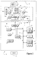
- a system 10 comprises a module 11 connected to a laptop computer 12.
- the module 11 is a 3G data card, implemented on a mini PCIe (PCI Express) card.
- the module 11 is internal to the laptop computer 12, in the sense that it is contained wholly within a housing 13 of the laptop computer 12 and cannot be removed therefrom without removing a cover (not shown) forming part of the housing. As such, the module is required to operate in a relatively high ambient temperature environment inside the laptop computer 12.
- the laptop computer 12 includes a fan 14 which is operable to expel hot air from within the housing 13 so as to maintain the temperature within the housing 13 within acceptable limits.
- the fan 14 is operated only when necessary, and is operated at a speed which is appropriate taking into account the ambient temperature within the housing 13, as measured by a temperature sensor 38.
- the laptop computer is shown in very schematic form. It will be appreciated that the laptop computer 12 includes many other components (display, keyboard, graphics card, etc), components are omitted from the Figure because they are not useful in understanding the invention.
- the laptop computer 12 includes a USB connector 15, which is mated with a corresponding USB connector 16 forming part of the module 11.
- a USB connector 15 which is mated with a corresponding USB connector 16 forming part of the module 11.
- the laptop computer 12 and the module 11 are able to communicate data and commands to one another.
- the USB connection allows the laptop computer 12 to provide electrical power to the module 11.
- a bus 17 of the laptop 12 is connected to the USB connector 15, 16 by a hardware interface 18.
- an interface 20 connects the USB connector 15, 16 to a bus 19 of the module 11.
- the bus 19 of the module 11 allows communication between a number of devices, namely a ROM 21, a microprocessor 22, and some RAM 23. Some of the RAM 23 constitutes a transmit buffer 24 for the module 11.
- a transmitter 25 is connected to the bus 19 via a transmitter-bus interface 26.
- a receiver 27 is connected to the bus 19 via a receiver-bus interface 28.
- the transmitter 25 and the receiver are connected to and share a common antenna 29A, which is located in the laptop 12 and is coupled to the transmitter 25 and the receiver 27 by an antenna connector 29B.
- a temperature sensor 30 is connected to provide temperature measurements to the microprocessor 22.
- the bus 17 of the laptop allows communication between some RAM 31, some of which constitutes a feed buffer 32 for the laptop 12, a CPU 33, storage 34, a dial-up modem 35 and a controller 36.
- Stored in the storage 34 is a program 37 constituting a driver for the USB interface 16, 18 and a user interface.
- a program 37 constituting a driver for the USB interface 16, 18 and a user interface.
- the module 11 is a cellular radio transceiver. It is operable to communicate with a 3G mobile telephone network 9 according to a WCDMA (Wideband Code Division Multiple Access) communications protocol of the 3G standard.
- the module 11 may or may not be operable according to the Rel5 version, relating to HSDPA (High Speed Downlink Packet Access).
- the module 11 is subscribed to cellular data service provided by the network 9. This is achieved by the cooperation of the microprocessor 22 and the RAM 23 to implement a protocol stack 40.
- the protocol stack 40 is conventional. It includes a layer 1 (L1) 41.
- the L1 41 is also known as the WCDMA physical layer. Above the L1 41 is a MAC (Medium Access Control) layer 42.
- This layer is also known as a WCDMA L2 protocol layer.
- an RLC (Radio Link Control) layer 44 This is also known as a WCDMA L3 protocol layer.
- the RLC layer 44 owns the transmit buffer 24.
- the protocol stack 40 is shown in the Figure, although it will be appreciated that it has no physical form but instead is formed by hardware operating under the control of software, relevant parts of which is held at run-time in the RAM 23.
- Receiver operation is not described here since it is not relevant to this explanation. Transmit operation is as follows.
- the protocol stack 40 maintains the transmit buffer 24 in the RAM 23.
- the transmit buffer stores data received from the laptop 12 prior to transmission through the transmitter 25 through the antenna 29.
- WCDMA Wideband Code Division Multiple Access
- a number of different transmit data rates are defined.
- a sample configuration is: Number of 336 bit blocks User Data Rate [kbps] Typical Weighting [User Data/Control Data] 12 384 15/4 4 128 15/8 2 64 15/15
- reducing the number of 336 bit blocks transmitted reduces the user data rate and also reduces the ratio of user data to control data.
- the configurations are known by UEs (User Equipments) such as the module 11. the number of blocks transmitted per unit of time determines the user data rate. If the network 9 allows the module 11 to transmit at 12 x 336 bits every 10 ms, this gives a user data rate of 384 kbps. This means that there is available uplink (UL) capacity to transmit 384 kbps, and is termed a 384 kbps bearer.
- UL uplink
- the L1 protocol layer 41 of the module 11 causes transmission of the data that is queued in the transmit buffer 24. If there is no data in the transmit buffer 24, there is no transmission to the network 9. If there is sufficient data in the buffer, then convention is that transmission occurs at the configuration specified by the network 9.
- the MAC layer 42 reduces the transmit data rate by reducing the number of blocks of 336 bits.
- the rate of data entering the transmit buffer is about 128 kbps
- the L1 layer 41 requires only 4 blocks of data (each of 336 bits) per 10 ms slot.
- the MAC layer 42 automatically adapts the transmits configuration to use the 4 x 336 bit configuration (128 kbps bearer).
- the rate of data entering the transmit buffer is around 64 kbps
- the L1 layer 41 requires only 2 blocks of data per 10 ms slot. In this case, the MAC layer 42 automatically adapts the transmits configuration to use the 2 x 336 bit configuration (64 kbps bearer).
- the L1 layer 41 switches between transmitting 2 blocks of data per 10 ms slot and 4 blocks of data per 10 ms slot. This occurs because the protocol stack 40 selects the number of blocks to transmit in a unit of time depending on the amount of data in the buffer. Similarly, if the rate of data entering the transmit buffer is between 0 kbps and 64 kbps, the L1 layer 41 switches between not transmitting and transmitting 2 blocks of data per 10 ms slot. Also, if the rate of data entering the transmit buffer is between 128 kbps and 384 kbps, the L1 layer 41 switches between transmitting 4 blocks of data per 10 ms slot and 12 blocks of data per 10 ms slot. Thus, by this scheme, the module 11 selects a transmit data rate which is dependent on the amount of data in the transmit buffer 24. This is conventional.
- the network 9 may define Traffic Volume Measurements (TVM).
- TVM Traffic Volume Measurements
- a TVM is a measure of the amount of data queued in the transmit buffer 24.
- TVMs are calculated in the MAC layer 42. If a TVM exceeds a network-defined threshold, it is an indication that the available uplink capacity on the allocated bearer is insufficient.
- the module 11 informs the network 9, and the network 9 can choose to allocate a larger bearer, and the module 11 is notified as appropriate. Conversely, if the amount of data queued in the transmit buffer 24 is less than a network-defined threshold, it is an indication that the available uplink capacity on the allocated bearer is excessive.
- the module 11 informs the network 9, and the network 9 then reconfigures the module 11 to use a lower data rate bearer. For example, it may withdraw the 12 x 336 bit (384 kbps) configuration. In this case, the network 9 may allocate the bearer to one or more other users.
- the module 11 still selects a transmit data rate which is dependent on the amount of data in the transmit buffer 24, although the transmit data rate cannot be greater than that allocated by the network 9.
- the microprocessor 22 of the module 11 is arranged under control of a program permanently stored in the ROM 21 to monitor the temperature of the module 11.
- This program is a WWAN (Wireless Wide Area Network) server 39, which is described below.
- Monitoring of the temperature of the module 11 involves periodic interrogation of the temperature sensor 30, with the sensor 30 responding with a signal indicative of the temperature of the module 11.
- the exact way in which the temperature of the module 11 is monitored is not crucial to the invention. It is however preferred that the module 11 is provided with two or more temperature sensors.
- the module 11 has three on-board temperature sensors 30a, 30b, 30c.
- the first sensor 30a is associated with an RF part of the module, which includes the transmitter 25 and the receiver 37.
- the second sensor 30b is associated with a VCTCXO (Voltage Controlled Temperature Compensated Oscillator) (not shown) which provides the transmitter 25 and the receiver 27 with oscillator signals.
- the third sensor 30c is associated with the RAM 23.
- the module temperature is taken to be the highest of the temperatures provided by the three sensors 30a-30c including any sensor tolerance.
- the temperature of the module 11 may instead be derived in any other suitable way.
- the WWAN server 39 is run on the module 11 using the microprocessor 22 and the RAM 23 to cause the microprocessor 22 to monitor the temperature of the temperature sensors 30a, 30b, 30c and thus the temperature of the module 11.
- the WWAN server 39 of the module 11 causes the microprocessor 22 to report to the laptop 12 via the USB interface 15, 16 when the temperature of the module 11 crosses one of a number of predetermined thresholds.
- the WWAN server 39 of the module 11 may be arranged to report, for instance periodically, the temperature of the module 11 to the laptop 12.
- temperature reporting may occur in response to a request, generated by the program 37, to the WWAN server 39 for a temperature measurement.
- the laptop 12 is able to determine when the temperature sensors 30a-30c indicate that a temperature has risen above certain thresholds.
- the laptop 12 also is able to determine when the temperature sensors 30a-30c indicate that a temperature has fallen below certain thresholds. These determinations are made from data received over the USB interface 15, 16.
- the driver program 37 causes the laptop 12 to adjust its operation on the basis of the monitored temperature of the module 11.
- the driver program 37 causes the laptop 12 to provide data to the module 11 for transmission at a rate which is dependent on the temperature of the module 11, as will now be described.
- Example thresholds are: Threshold Value [°C] TCritical 80 TRadioOff 75 TRadioOn 73 TThrottle2 70 TThrottle1 65
- the driver program is operable to operate in a state defined by the state machine 50 diagram of Figure 2.
- the driver can operate in one of six states: 'module on' 51, 'fault mode' 52, 'radio on' 53, 'radio off' 54, 'throttle 1' 55 and 'throttle 2' 56.
- the 'module on' state 51 is entered when the laptop 12 boots up and power is applied to the module 11; or following recovery from the 'fault mode' 52.
- the WWAN server 39 reads the temperature of the module 11, and in conjunction with a software radio enable/disable feature (not shown) of the laptop 12, and W_DISABLE configurations, causes a state transition to 'radio off' state 54, 'radio on' state 53 or 'fault mode' state 52 as appropriate
- the 'fault mode' state 52 is the fault condition and is only entered (from any state), when the module temperature exceeds a critical component temperature: TCritical. This can be used to prove that the warranty of the module 11 has been violated.
- the module 11 first informs the laptop 12 that this state is being entered, and then enters a 'power down' state. This ensures that the module 11 is in its lowest operational state, even though power is still supplied to the module 11 by the USB interface 15, 16.
- the laptop thermal design should be such that the 'fault mode' state 52 is never entered, as the excessive module temperature will be due a high ambient temperature in the laptop 12, and not from the module 11. However if this mode is entered, then the WWAN server 39 writes data to permanent memory (i.e. the ROM 21) to indicate that this has happened
- the 'fault mode' state 52 can only be exited when the laptop 12 reboots: 'module on' state 51 is then entered.
- the 'radio on' state 53 is the usual operational state of the module 11. In this state, the module temperature is low enough to permit data transmission at full rate; and both software and hardware radio controls are set to enable a network connection. This state is left if either there is a rise in module temperature or there is a reason why the radio cannot be operated (e.g. on entering "flight mode", where radio operation is prohibited).
- the 'radio off' state 54 is the mode in which communication to/from the network 9 is prohibited.
- the most likely triggers for entering this state are excessive module temperature and either software or hardware radio controls preventing radio operation (e.g. entering "flight mode").
- the module 11 informs the laptop 12 that this state is being entered, and a timer is started in the laptop by the driver program 37. Once the timer (ElapsedTime) exceeds a predetermined value, equal to CoolingTime, the driver program 37 of the laptop 12 polls the WWAN server 39 to report the temperature of the module 11.. The WWAN Server 39 then reads the module temperature and reports the temperature to the driver program 37. If the module temperature is still high, such that only the 'radio off' state 54 or the 'fault mode' state 52 can be entered, then the procedure is repeated, but with an increased CoolingTime timer value.
- the 'throttle 1' state 55 is identical to the 'radio on' state 53, except that the UL data rate is throttled.
- the 'throttle 2' state 56 is identical to the 'throttle 1' state 55, except that the UL data rate is throttled to an even lower data rate.
- State change 1 (denoted by a 1 in a circle in the Figure) occurs only when power is first applied to the module (3.3 V rail), the WWAN server 39 detects that the module temperature is below TCritical, a software command is set to enable the WWAN radio, and a hardware W_DISABLE is disabled (high) to enable the WWAN radio. This causes the module to transition to the 'radio on' state 53.
- State change 2 (denoted by a 2 in a circle in the Figure) occurs from either the initial power on ('module on' state 51) or 'radio on' state 53.
- This state change occurs only when the WWAN server 39 detects that the module temperature is above TRadioOff, but below TCritical, or software command is set to disable the WWAN radio, or hardware W_DISABLE is (low) to disable the WWAN radio. With this state change, the module 11 transitions to the 'radio off' state 54.
- State change 3 (denoted by a 3 in a circle in the Figure) can occur from any state. It occurs when the WWAN server 39 detects that the module temperature is above TCritical, the state change is into the 'fault mode' 52.
- State change 4 (denoted by a 4 in a circle in the Figure) occurs when the module is in the 'fault mode' state 52 and the laptop 12 powers off and reboots.
- the module leaves the 'fault mode' state 52 and transitions to the 'module on' state 51 such that "normal" operation can be resumed. This is the only recovery from the 'fault mode' state 52.
- State change 5 (denoted by a 5 in a circle in the Figure) occurs from any state where there are restrictions on radio operation (disabled or throttled). This state change occurs when the WWAN server 39 detects that the module temperature is below TThrottle1 and TRadioOn, and a software command is set to enable the WWAN radio, and the hardware W_DISABLE is disabled (high) to enable the WWAN radio. With this state change, the module 11 transitions to the 'radio on' state 53, where radio operation is unrestricted.
- State change 6 (denoted by a 6 in a circle in the Figure) can occur from any operational state. It occurs when the WWAN server 39 detects that the module temperature is above TThrottle1, but below TRadioOn and a software command is set to enable the WWAN radio, and the hardware W_DISABLE is disabled (high) to enable the WWAN radio. With this state change, the module 11 transitions to the 'throttle 1' state 55.
- State change 7 (denoted by a 7 in a circle in the Figure) can occur from any operational state. It occurs when the WWAN server 39 detects that the module temperature is above TThrottle2, but below TRadioOn and a software command is set to enable the WWAN radio, and the hardware W_DISABLE is disabled (high) to enable the WWAN radio. With this state change, the module 11 transitions to the 'throttle 2' state 56.
- the cellular software and radio are disabled. This simplifies the interface between the protocol software 40 and the WWAN server 39, compared to merely disabling the transmitter. This does result in the module 11 disconnecting from the network 9, so an indication of this is provided to software of the laptop 12.
- the cellular software and radio can be re-enabled and the module 11 performs a cell search and re-registers with the network 9.
- the driver program 37 creates the feed buffer 32.
- the driver program 37 starts a timer, ticking at a fixed rate, only when there is data in the feed buffer 32.
- the tick period can be called the "Throttle Timer Period".
- no throttling i.e. the module is in 'radio on' state 53
- the rate at which data is sent over the USB connection 15, 16 is governed by conventional flow control in the protocol software 40.
- a cap on the amount of data sent over the USB connection 15, 16 in the Throttle Timer Period is made.
- the first cap is a maximum amount of data that can be sent, and corresponds to x bytes.
- a second cap on the amount of data sent over the USB connection in the Throttle Timer Period is made.
- the second cap corresponds to y bytes, where x > y.
- x and y may be configurable dynamically, but they preferably are fixed.
- the second cap (y bytes) corresponds to the lowest possible UL data rate, i.e. 64 kbps.
- the first cap (x bytes) corresponds to the next lowest data rate, i.e. 128 kbps.
- the values of x and y depends on the length of the Throttle Timer Period, but it is easy for the driver program 37 to calculate suitable values.
- the driver program 37 thus defines plural contiguous and sequential time periods, each having a length equal to the Throttle Timer Period, and limits the amount of data that is fed to the USB interface in each of the time periods.
- data can be transmitted burstily, taking an average using a resolution less than the Throttle Timer Period provides a throttled and steady feeding data rate.
- the amount of data that is transmitted in one Throttle Timer Period preferably is small compared to the size of the transmit buffer 24.
- the data is sent from the feed buffer 32 to the module 11 via the USB connection 15, 16 at the usual full-speed USB data rate of 12 Mbps.
- Data rate control is effected by inserting delays between packets. The effect of this is that the data entering the module 11, and hence the protocol software stack 40, is in bursts.
- the average data rate is controlled by the driver program 37 to be the required data rate mentioned above.
- the value of the Throttle Timer Period is selected so as to allow smooth operation of the module 11, i.e. is small enough so as to prevent the transmit data rate selected by the protocol stack 40 or the network 9 from unnecessary switching but is large enough so as to allow full size packets to be sent from the feed buffer 32 to the module 11 whilst achieving the required average data rate.
- the module 11 When throttling data flow from the feed buffer 32 to the module 11, the module 11 normally will for a short time continue to transmit data at higher data rate. After the data rate has begun to be throttled, the fact that the transmit data rate is significantly greater than the rate at which data is entered into the transmit buffer 23 from the laptop 12 means that the buffer begins to empty of data. After a short time, the amount of data stored in the buffer falls to a point where the L1 layer 41 determines that the transmit data rate is too high. At this time, the L1 layer 41 changes the transmit data rate to a lower rate. The reduction in transmit data rate occurs immediately the L1 layer 41 calculates the new required block size.
- feeding data from the feed buffer correctly can ensure that the possibility is no greater than if transmission had continued at the greater data rate.
- the reduced amount of data in the buffer can cause the network 9 to remove some bearer from that allocated to the module 11.
- the adjustment of the data rate passing to the transmit buffer 24 over the USB connection 15, 16 results in the protocol software 40 automatically reducing the transmit data rate, and thus reducing the amount of heat generated by the module 11. This is achieved without any change to the protocol software 40, which thus can be conventional.
- driver program 37 resides in the laptop 12 means that it does not have any negative effect on other programs.
- the presence of the driver program 37 on the laptop 12 also is advantageous since the availability of the RAM 31 means that more data can be buffered on the laptop 12 than could be buffered on the module 11.
- the effect of this operation is a reduction in transmit power, and thus a reduction in generated heat, when the module 11 is hot. Reducing the heat generated by the module 11 increases the probability of the module 11 being able to continue. Put another way, reducing the transmit data rate decreases the likelihood that the module 11 will reach its maximum operating temperature and thus be switched off.
- the inventors have found that, for WCDMA (including HSDPA), the only way to reduce transmitter power is to reduce the transmit data rate. If the module 11 reduces transmit power without reducing data rate, the mobile phone network 9 requests the module 11 to increase the transmit power up to the correct level. In WCDMA, because there is less spreading of the data at higher data rates, the need to achieve the required signal-to-noise ratio when transmitting at a higher data rate gives rise to higher power consumption.
- WCDMA including HSDPA
- the network 9 defines a different transmit power for each of the UL (uplink) data rates that the network 9 supports. This is achieved by weighting the relative powers for the control data and user data.
- the power savings resulting from the above mentioned sample configuration are: Number of 336 bit blocks User Data Rate [kbps] Typical Weighting [User Data/Control Data] Estimated Drop in Tx power [dB] 12 384 15/4 - 4 128 15/8 5 2 64 15/15 9
- the module can use a lower weighting which in turn equates to a lower transmit power.
- the transmit power decreases by approximately 9 dB. It will be appreciated, though, that any decrease in transmit power resulting from a reduced transmit data rate is solely dependent on the configuration of the weightings for each data rate set by the network 9, which are known by UEs.
- FIG. 3 An example operation of the algorithm implemented in the driver program 37 is shown in Figure 3.
- the temperature rises above the Tthrottle2 threshold. This causes the module 11 to transition to the 'throttle 2' state 56. This reduces the data rate to a low data rate, and thus reduces further the amount of heat generated by the module 11.
- the temperature of the module rises further above the TRadioOn threshold, which does not cause any transitions, then at point C falls below the TThrottle2 threshold. This causes the module 11 to transition to the 'throttle 1' state 55. This increases the data rate, and thus the amount of heat generated by the module 11.
- the temperature of the module 11 then falls below the TRadioOff threshold, which does not cause any transitions, then at point F rises below the TRadioOn threshold. This causes the module to transition to the 'throttle 2' state 56.
- the temperature of the module 11 then rises again above the TRadioOn threshold, which again does not cause any transitions, then at point G rises above the TRadioOff threshold. This causes the module to transition to the 'radio off' state 54. At this stage, the module 11 is generating little or no heat. The temperature of the module 11 continues to rise, because of external heat sources, until at point H it rises above the TCritical threshold. At this point, the module 11 transitions to 'fault mode' state 52. Here, the module 11 writes to permanent memory that fault mode was entered. Operation of the radio cannot begin again until the temperature falls below the TRadioOn threshold.
- TRadioOn and TRadioOff provide hysteresis, which help to prevent a ping-pong effect.
- Hysteresis is not applied on the throttling thresholds since it is thought that ping-ponging between data rates is not particularly problematic.
- the two throttling thresholds could be used as a single throttling threshold with hysteresis.
- the module 11 may in an operational state either be 'radio on', 'throttle' or 'radio off'. This may be achieved using the algorithm described above by a small modification of the temperature thresholds, as follows: Threshold Value [ °C] TCritical 80 TRadioOff 75 TRadioOn 70 TThrottle2 70 TThrottle1 65
- the invention is applicable to transmitters operating according to standards other than WCDMA standards.
- the above embodiment relates to a PCIe miniaturecard internal to a laptop computer 12, the skilled person will appreciate that the invention has broader applicability than this.
- the invention in some instances can be embodied as a module which largely is external to a laptop computer or other device.
- the invention may be applicable to WCDMA (including HSDPA) cards or modules which are connectable with PCMCIA slots and the like such that a part of the card or module is internal and part is external.
- the invention is applicable in some aspects also to apparatus in which a radio module is connected to another device without a specific interface, for instance when the module and the device are hard-wired together.
- the invention is applicable also to mobile telephones, smart phones, PDAs (Personal Digital Assistants) and the like which have internal or partly internal transceiver modules.
- the one or more temperature sensors on the output of which decisions are made may not be associated specifically with the module itself, but may be located at any suitable position within the host device.
Landscapes
- Engineering & Computer Science (AREA)
- Theoretical Computer Science (AREA)
- Physics & Mathematics (AREA)
- General Engineering & Computer Science (AREA)
- General Physics & Mathematics (AREA)
- Thermal Sciences (AREA)
- Microelectronics & Electronic Packaging (AREA)
- Human Computer Interaction (AREA)
- Mobile Radio Communication Systems (AREA)
- Information Transfer Systems (AREA)
- Communication Control (AREA)
Applications Claiming Priority (1)
| Application Number | Priority Date | Filing Date | Title |
|---|---|---|---|
| US11/479,170 US20080059658A1 (en) | 2006-06-29 | 2006-06-29 | Controlling the feeding of data from a feed buffer |
Publications (2)
| Publication Number | Publication Date |
|---|---|
| EP1873652A2 true EP1873652A2 (fr) | 2008-01-02 |
| EP1873652A3 EP1873652A3 (fr) | 2008-01-09 |
Family
ID=38544075
Family Applications (1)
| Application Number | Title | Priority Date | Filing Date |
|---|---|---|---|
| EP07109780A Ceased EP1873652A3 (fr) | 2006-06-29 | 2007-06-07 | Contrôle de l'introduction de données à partir d'un tampon d'alimentation |
Country Status (4)
| Country | Link |
|---|---|
| US (1) | US20080059658A1 (fr) |
| EP (1) | EP1873652A3 (fr) |
| KR (1) | KR20080001660A (fr) |
| CN (1) | CN101097474A (fr) |
Cited By (5)
| Publication number | Priority date | Publication date | Assignee | Title |
|---|---|---|---|---|
| WO2009143487A2 (fr) | 2008-05-23 | 2009-11-26 | Qualcomm Incorporated | Gestion thermique pour des modules de données |
| US20110038265A1 (en) * | 2009-08-11 | 2011-02-17 | Huawei Device Co., Ltd | Traffic Control Method, Device and Terminal |
| US8498328B2 (en) | 2009-10-13 | 2013-07-30 | Qualcomm Incorporated | Energy management for wireless devices |
| WO2014113825A3 (fr) * | 2013-01-16 | 2014-09-12 | Qualcomm Incorporated | Atténuation thermique dans des dispositifs actifs doubles à double abonnement |
| EP3505042A1 (fr) * | 2017-12-28 | 2019-07-03 | Ethicon LLC | Concentrateur de communication et dispositif de stockage destiné à stocker des paramètres et l'état d'un dispositif chirurgical à partager avec des systèmes d'analyse basés sur le cloud |
Families Citing this family (136)
| Publication number | Priority date | Publication date | Assignee | Title |
|---|---|---|---|---|
| KR100939722B1 (ko) | 2008-08-11 | 2010-02-01 | 엘지전자 주식회사 | 데이터 전송 방법 및 이를 위한 사용자 기기 |
| GB2483057B (en) * | 2010-08-20 | 2012-11-28 | Wireless Tech Solutions Llc | Apparatus, method and system for managing data transmission |
| US11871901B2 (en) | 2012-05-20 | 2024-01-16 | Cilag Gmbh International | Method for situational awareness for surgical network or surgical network connected device capable of adjusting function based on a sensed situation or usage |
| US11504192B2 (en) | 2014-10-30 | 2022-11-22 | Cilag Gmbh International | Method of hub communication with surgical instrument systems |
| US20160183117A1 (en) * | 2014-12-17 | 2016-06-23 | Mediatek Inc. | Method and apparatus for throttling uplink data based on temperature state |
| KR101539067B1 (ko) * | 2015-02-10 | 2015-07-22 | 엘아이지넥스원 주식회사 | 통풍기 제어 장치 |
| CN105116978A (zh) * | 2015-08-17 | 2015-12-02 | 山东超越数控电子有限公司 | 一种基于龙芯处理器的温度控制方法 |
| US11793537B2 (en) | 2017-10-30 | 2023-10-24 | Cilag Gmbh International | Surgical instrument comprising an adaptive electrical system |
| US11317919B2 (en) | 2017-10-30 | 2022-05-03 | Cilag Gmbh International | Clip applier comprising a clip crimping system |
| US11911045B2 (en) | 2017-10-30 | 2024-02-27 | Cllag GmbH International | Method for operating a powered articulating multi-clip applier |
| US11229436B2 (en) | 2017-10-30 | 2022-01-25 | Cilag Gmbh International | Surgical system comprising a surgical tool and a surgical hub |
| US11311342B2 (en) | 2017-10-30 | 2022-04-26 | Cilag Gmbh International | Method for communicating with surgical instrument systems |
| US11801098B2 (en) | 2017-10-30 | 2023-10-31 | Cilag Gmbh International | Method of hub communication with surgical instrument systems |
| US11026687B2 (en) | 2017-10-30 | 2021-06-08 | Cilag Gmbh International | Clip applier comprising clip advancing systems |
| US11510741B2 (en) | 2017-10-30 | 2022-11-29 | Cilag Gmbh International | Method for producing a surgical instrument comprising a smart electrical system |
| US11564756B2 (en) | 2017-10-30 | 2023-01-31 | Cilag Gmbh International | Method of hub communication with surgical instrument systems |
| US11291510B2 (en) | 2017-10-30 | 2022-04-05 | Cilag Gmbh International | Method of hub communication with surgical instrument systems |
| US11969142B2 (en) | 2017-12-28 | 2024-04-30 | Cilag Gmbh International | Method of compressing tissue within a stapling device and simultaneously displaying the location of the tissue within the jaws |
| US20190201112A1 (en) | 2017-12-28 | 2019-07-04 | Ethicon Llc | Computer implemented interactive surgical systems |
| US10943454B2 (en) | 2017-12-28 | 2021-03-09 | Ethicon Llc | Detection and escalation of security responses of surgical instruments to increasing severity threats |
| US11109866B2 (en) | 2017-12-28 | 2021-09-07 | Cilag Gmbh International | Method for circular stapler control algorithm adjustment based on situational awareness |
| US11678881B2 (en) | 2017-12-28 | 2023-06-20 | Cilag Gmbh International | Spatial awareness of surgical hubs in operating rooms |
| US10755813B2 (en) | 2017-12-28 | 2020-08-25 | Ethicon Llc | Communication of smoke evacuation system parameters to hub or cloud in smoke evacuation module for interactive surgical platform |
| US11432885B2 (en) | 2017-12-28 | 2022-09-06 | Cilag Gmbh International | Sensing arrangements for robot-assisted surgical platforms |
| US11045591B2 (en) | 2017-12-28 | 2021-06-29 | Cilag Gmbh International | Dual in-series large and small droplet filters |
| US10695081B2 (en) | 2017-12-28 | 2020-06-30 | Ethicon Llc | Controlling a surgical instrument according to sensed closure parameters |
| US10966791B2 (en) | 2017-12-28 | 2021-04-06 | Ethicon Llc | Cloud-based medical analytics for medical facility segmented individualization of instrument function |
| US11571234B2 (en) | 2017-12-28 | 2023-02-07 | Cilag Gmbh International | Temperature control of ultrasonic end effector and control system therefor |
| US10892995B2 (en) | 2017-12-28 | 2021-01-12 | Ethicon Llc | Surgical network determination of prioritization of communication, interaction, or processing based on system or device needs |
| US11056244B2 (en) | 2017-12-28 | 2021-07-06 | Cilag Gmbh International | Automated data scaling, alignment, and organizing based on predefined parameters within surgical networks |
| US11419630B2 (en) | 2017-12-28 | 2022-08-23 | Cilag Gmbh International | Surgical system distributed processing |
| US11589888B2 (en) | 2017-12-28 | 2023-02-28 | Cilag Gmbh International | Method for controlling smart energy devices |
| US20190201042A1 (en) | 2017-12-28 | 2019-07-04 | Ethicon Llc | Determining the state of an ultrasonic electromechanical system according to frequency shift |
| US20190201090A1 (en) | 2017-12-28 | 2019-07-04 | Ethicon Llc | Capacitive coupled return path pad with separable array elements |
| US11026751B2 (en) | 2017-12-28 | 2021-06-08 | Cilag Gmbh International | Display of alignment of staple cartridge to prior linear staple line |
| US11786251B2 (en) | 2017-12-28 | 2023-10-17 | Cilag Gmbh International | Method for adaptive control schemes for surgical network control and interaction |
| US11304745B2 (en) | 2017-12-28 | 2022-04-19 | Cilag Gmbh International | Surgical evacuation sensing and display |
| US20190206569A1 (en) | 2017-12-28 | 2019-07-04 | Ethicon Llc | Method of cloud based data analytics for use with the hub |
| US11633237B2 (en) | 2017-12-28 | 2023-04-25 | Cilag Gmbh International | Usage and technique analysis of surgeon / staff performance against a baseline to optimize device utilization and performance for both current and future procedures |
| US11213359B2 (en) | 2017-12-28 | 2022-01-04 | Cilag Gmbh International | Controllers for robot-assisted surgical platforms |
| US10932872B2 (en) | 2017-12-28 | 2021-03-02 | Ethicon Llc | Cloud-based medical analytics for linking of local usage trends with the resource acquisition behaviors of larger data set |
| US11304763B2 (en) | 2017-12-28 | 2022-04-19 | Cilag Gmbh International | Image capturing of the areas outside the abdomen to improve placement and control of a surgical device in use |
| US12062442B2 (en) | 2017-12-28 | 2024-08-13 | Cilag Gmbh International | Method for operating surgical instrument systems |
| US11273001B2 (en) | 2017-12-28 | 2022-03-15 | Cilag Gmbh International | Surgical hub and modular device response adjustment based on situational awareness |
| US11559308B2 (en) | 2017-12-28 | 2023-01-24 | Cilag Gmbh International | Method for smart energy device infrastructure |
| US11304699B2 (en) | 2017-12-28 | 2022-04-19 | Cilag Gmbh International | Method for adaptive control schemes for surgical network control and interaction |
| US11147607B2 (en) | 2017-12-28 | 2021-10-19 | Cilag Gmbh International | Bipolar combination device that automatically adjusts pressure based on energy modality |
| US11540855B2 (en) | 2017-12-28 | 2023-01-03 | Cilag Gmbh International | Controlling activation of an ultrasonic surgical instrument according to the presence of tissue |
| WO2019133143A1 (fr) | 2017-12-28 | 2019-07-04 | Ethicon Llc | Concentrateur chirurgical et ajustement de réponse de dispositif modulaire sur la base d'une perception situationnelle |
| US11013563B2 (en) | 2017-12-28 | 2021-05-25 | Ethicon Llc | Drive arrangements for robot-assisted surgical platforms |
| US11410259B2 (en) | 2017-12-28 | 2022-08-09 | Cilag Gmbh International | Adaptive control program updates for surgical devices |
| US11464535B2 (en) | 2017-12-28 | 2022-10-11 | Cilag Gmbh International | Detection of end effector emersion in liquid |
| US11051876B2 (en) | 2017-12-28 | 2021-07-06 | Cilag Gmbh International | Surgical evacuation flow paths |
| US11832840B2 (en) | 2017-12-28 | 2023-12-05 | Cilag Gmbh International | Surgical instrument having a flexible circuit |
| US11308075B2 (en) | 2017-12-28 | 2022-04-19 | Cilag Gmbh International | Surgical network, instrument, and cloud responses based on validation of received dataset and authentication of its source and integrity |
| US11317937B2 (en) | 2018-03-08 | 2022-05-03 | Cilag Gmbh International | Determining the state of an ultrasonic end effector |
| US11278281B2 (en) | 2017-12-28 | 2022-03-22 | Cilag Gmbh International | Interactive surgical system |
| JP2021509061A (ja) | 2017-12-28 | 2021-03-18 | エシコン エルエルシーEthicon LLC | 状況認識に基づく外科用デバイスの機能の調節 |
| US11832899B2 (en) | 2017-12-28 | 2023-12-05 | Cilag Gmbh International | Surgical systems with autonomously adjustable control programs |
| US11446052B2 (en) | 2017-12-28 | 2022-09-20 | Cilag Gmbh International | Variation of radio frequency and ultrasonic power level in cooperation with varying clamp arm pressure to achieve predefined heat flux or power applied to tissue |
| US11423007B2 (en) | 2017-12-28 | 2022-08-23 | Cilag Gmbh International | Adjustment of device control programs based on stratified contextual data in addition to the data |
| US10892899B2 (en) | 2017-12-28 | 2021-01-12 | Ethicon Llc | Self describing data packets generated at an issuing instrument |
| US10758310B2 (en) | 2017-12-28 | 2020-09-01 | Ethicon Llc | Wireless pairing of a surgical device with another device within a sterile surgical field based on the usage and situational awareness of devices |
| US10918310B2 (en) | 2018-01-03 | 2021-02-16 | Biosense Webster (Israel) Ltd. | Fast anatomical mapping (FAM) using volume filling |
| US12396806B2 (en) | 2017-12-28 | 2025-08-26 | Cilag Gmbh International | Adjustment of a surgical device function based on situational awareness |
| US11666331B2 (en) | 2017-12-28 | 2023-06-06 | Cilag Gmbh International | Systems for detecting proximity of surgical end effector to cancerous tissue |
| US11100631B2 (en) | 2017-12-28 | 2021-08-24 | Cilag Gmbh International | Use of laser light and red-green-blue coloration to determine properties of back scattered light |
| US11284936B2 (en) | 2017-12-28 | 2022-03-29 | Cilag Gmbh International | Surgical instrument having a flexible electrode |
| US10849697B2 (en) | 2017-12-28 | 2020-12-01 | Ethicon Llc | Cloud interface for coupled surgical devices |
| US11786245B2 (en) | 2017-12-28 | 2023-10-17 | Cilag Gmbh International | Surgical systems with prioritized data transmission capabilities |
| US10595887B2 (en) | 2017-12-28 | 2020-03-24 | Ethicon Llc | Systems for adjusting end effector parameters based on perioperative information |
| US11602393B2 (en) | 2017-12-28 | 2023-03-14 | Cilag Gmbh International | Surgical evacuation sensing and generator control |
| US11234756B2 (en) | 2017-12-28 | 2022-02-01 | Cilag Gmbh International | Powered surgical tool with predefined adjustable control algorithm for controlling end effector parameter |
| US11744604B2 (en) | 2017-12-28 | 2023-09-05 | Cilag Gmbh International | Surgical instrument with a hardware-only control circuit |
| US11076921B2 (en) | 2017-12-28 | 2021-08-03 | Cilag Gmbh International | Adaptive control program updates for surgical hubs |
| US10944728B2 (en) | 2017-12-28 | 2021-03-09 | Ethicon Llc | Interactive surgical systems with encrypted communication capabilities |
| US11160605B2 (en) | 2017-12-28 | 2021-11-02 | Cilag Gmbh International | Surgical evacuation sensing and motor control |
| US11419667B2 (en) | 2017-12-28 | 2022-08-23 | Cilag Gmbh International | Ultrasonic energy device which varies pressure applied by clamp arm to provide threshold control pressure at a cut progression location |
| US11266468B2 (en) | 2017-12-28 | 2022-03-08 | Cilag Gmbh International | Cooperative utilization of data derived from secondary sources by intelligent surgical hubs |
| US11903601B2 (en) | 2017-12-28 | 2024-02-20 | Cilag Gmbh International | Surgical instrument comprising a plurality of drive systems |
| US11291495B2 (en) | 2017-12-28 | 2022-04-05 | Cilag Gmbh International | Interruption of energy due to inadvertent capacitive coupling |
| US12458351B2 (en) | 2017-12-28 | 2025-11-04 | Cilag Gmbh International | Variable output cartridge sensor assembly |
| US11896322B2 (en) | 2017-12-28 | 2024-02-13 | Cilag Gmbh International | Sensing the patient position and contact utilizing the mono-polar return pad electrode to provide situational awareness to the hub |
| US11096693B2 (en) | 2017-12-28 | 2021-08-24 | Cilag Gmbh International | Adjustment of staple height of at least one row of staples based on the sensed tissue thickness or force in closing |
| US11364075B2 (en) | 2017-12-28 | 2022-06-21 | Cilag Gmbh International | Radio frequency energy device for delivering combined electrical signals |
| US11389164B2 (en) | 2017-12-28 | 2022-07-19 | Cilag Gmbh International | Method of using reinforced flexible circuits with multiple sensors to optimize performance of radio frequency devices |
| US11771487B2 (en) | 2017-12-28 | 2023-10-03 | Cilag Gmbh International | Mechanisms for controlling different electromechanical systems of an electrosurgical instrument |
| US11132462B2 (en) | 2017-12-28 | 2021-09-28 | Cilag Gmbh International | Data stripping method to interrogate patient records and create anonymized record |
| US11559307B2 (en) | 2017-12-28 | 2023-01-24 | Cilag Gmbh International | Method of robotic hub communication, detection, and control |
| US10987178B2 (en) | 2017-12-28 | 2021-04-27 | Ethicon Llc | Surgical hub control arrangements |
| US11311306B2 (en) | 2017-12-28 | 2022-04-26 | Cilag Gmbh International | Surgical systems for detecting end effector tissue distribution irregularities |
| US11529187B2 (en) | 2017-12-28 | 2022-12-20 | Cilag Gmbh International | Surgical evacuation sensor arrangements |
| US12096916B2 (en) | 2017-12-28 | 2024-09-24 | Cilag Gmbh International | Method of sensing particulate from smoke evacuated from a patient, adjusting the pump speed based on the sensed information, and communicating the functional parameters of the system to the hub |
| US11864728B2 (en) | 2017-12-28 | 2024-01-09 | Cilag Gmbh International | Characterization of tissue irregularities through the use of mono-chromatic light refractivity |
| US11179208B2 (en) | 2017-12-28 | 2021-11-23 | Cilag Gmbh International | Cloud-based medical analytics for security and authentication trends and reactive measures |
| US11818052B2 (en) | 2017-12-28 | 2023-11-14 | Cilag Gmbh International | Surgical network determination of prioritization of communication, interaction, or processing based on system or device needs |
| US11464559B2 (en) | 2017-12-28 | 2022-10-11 | Cilag Gmbh International | Estimating state of ultrasonic end effector and control system therefor |
| US11969216B2 (en) | 2017-12-28 | 2024-04-30 | Cilag Gmbh International | Surgical network recommendations from real time analysis of procedure variables against a baseline highlighting differences from the optimal solution |
| US11576677B2 (en) | 2017-12-28 | 2023-02-14 | Cilag Gmbh International | Method of hub communication, processing, display, and cloud analytics |
| US11937769B2 (en) | 2017-12-28 | 2024-03-26 | Cilag Gmbh International | Method of hub communication, processing, storage and display |
| US11857152B2 (en) | 2017-12-28 | 2024-01-02 | Cilag Gmbh International | Surgical hub spatial awareness to determine devices in operating theater |
| US11424027B2 (en) | 2017-12-28 | 2022-08-23 | Cilag Gmbh International | Method for operating surgical instrument systems |
| US11659023B2 (en) | 2017-12-28 | 2023-05-23 | Cilag Gmbh International | Method of hub communication |
| US11069012B2 (en) | 2017-12-28 | 2021-07-20 | Cilag Gmbh International | Interactive surgical systems with condition handling of devices and data capabilities |
| US11376002B2 (en) | 2017-12-28 | 2022-07-05 | Cilag Gmbh International | Surgical instrument cartridge sensor assemblies |
| US11612444B2 (en) | 2017-12-28 | 2023-03-28 | Cilag Gmbh International | Adjustment of a surgical device function based on situational awareness |
| US12127729B2 (en) | 2017-12-28 | 2024-10-29 | Cilag Gmbh International | Method for smoke evacuation for surgical hub |
| US11166772B2 (en) | 2017-12-28 | 2021-11-09 | Cilag Gmbh International | Surgical hub coordination of control and communication of operating room devices |
| US11896443B2 (en) | 2017-12-28 | 2024-02-13 | Cilag Gmbh International | Control of a surgical system through a surgical barrier |
| US11257589B2 (en) | 2017-12-28 | 2022-02-22 | Cilag Gmbh International | Real-time analysis of comprehensive cost of all instrumentation used in surgery utilizing data fluidity to track instruments through stocking and in-house processes |
| US11304720B2 (en) | 2017-12-28 | 2022-04-19 | Cilag Gmbh International | Activation of energy devices |
| US11324557B2 (en) | 2017-12-28 | 2022-05-10 | Cilag Gmbh International | Surgical instrument with a sensing array |
| US11253315B2 (en) | 2017-12-28 | 2022-02-22 | Cilag Gmbh International | Increasing radio frequency to create pad-less monopolar loop |
| US11998193B2 (en) | 2017-12-28 | 2024-06-04 | Cilag Gmbh International | Method for usage of the shroud as an aspect of sensing or controlling a powered surgical device, and a control algorithm to adjust its default operation |
| US12376855B2 (en) | 2017-12-28 | 2025-08-05 | Cilag Gmbh International | Safety systems for smart powered surgical stapling |
| US11259830B2 (en) | 2018-03-08 | 2022-03-01 | Cilag Gmbh International | Methods for controlling temperature in ultrasonic device |
| US11464532B2 (en) | 2018-03-08 | 2022-10-11 | Cilag Gmbh International | Methods for estimating and controlling state of ultrasonic end effector |
| US12303159B2 (en) | 2018-03-08 | 2025-05-20 | Cilag Gmbh International | Methods for estimating and controlling state of ultrasonic end effector |
| US11986233B2 (en) | 2018-03-08 | 2024-05-21 | Cilag Gmbh International | Adjustment of complex impedance to compensate for lost power in an articulating ultrasonic device |
| US11090047B2 (en) | 2018-03-28 | 2021-08-17 | Cilag Gmbh International | Surgical instrument comprising an adaptive control system |
| US11219453B2 (en) | 2018-03-28 | 2022-01-11 | Cilag Gmbh International | Surgical stapling devices with cartridge compatible closure and firing lockout arrangements |
| US11259806B2 (en) | 2018-03-28 | 2022-03-01 | Cilag Gmbh International | Surgical stapling devices with features for blocking advancement of a camming assembly of an incompatible cartridge installed therein |
| US11096688B2 (en) | 2018-03-28 | 2021-08-24 | Cilag Gmbh International | Rotary driven firing members with different anvil and channel engagement features |
| US11207067B2 (en) | 2018-03-28 | 2021-12-28 | Cilag Gmbh International | Surgical stapling device with separate rotary driven closure and firing systems and firing member that engages both jaws while firing |
| US11471156B2 (en) | 2018-03-28 | 2022-10-18 | Cilag Gmbh International | Surgical stapling devices with improved rotary driven closure systems |
| US10973520B2 (en) | 2018-03-28 | 2021-04-13 | Ethicon Llc | Surgical staple cartridge with firing member driven camming assembly that has an onboard tissue cutting feature |
| US11129611B2 (en) | 2018-03-28 | 2021-09-28 | Cilag Gmbh International | Surgical staplers with arrangements for maintaining a firing member thereof in a locked configuration unless a compatible cartridge has been installed therein |
| US11278280B2 (en) | 2018-03-28 | 2022-03-22 | Cilag Gmbh International | Surgical instrument comprising a jaw closure lockout |
| US11259807B2 (en) | 2019-02-19 | 2022-03-01 | Cilag Gmbh International | Staple cartridges with cam surfaces configured to engage primary and secondary portions of a lockout of a surgical stapling device |
| US11357503B2 (en) | 2019-02-19 | 2022-06-14 | Cilag Gmbh International | Staple cartridge retainers with frangible retention features and methods of using same |
| US11369377B2 (en) | 2019-02-19 | 2022-06-28 | Cilag Gmbh International | Surgical stapling assembly with cartridge based retainer configured to unlock a firing lockout |
| US11464511B2 (en) | 2019-02-19 | 2022-10-11 | Cilag Gmbh International | Surgical staple cartridges with movable authentication key arrangements |
| US11317915B2 (en) | 2019-02-19 | 2022-05-03 | Cilag Gmbh International | Universal cartridge based key feature that unlocks multiple lockout arrangements in different surgical staplers |
| USD950728S1 (en) | 2019-06-25 | 2022-05-03 | Cilag Gmbh International | Surgical staple cartridge |
| USD964564S1 (en) | 2019-06-25 | 2022-09-20 | Cilag Gmbh International | Surgical staple cartridge retainer with a closure system authentication key |
| USD952144S1 (en) | 2019-06-25 | 2022-05-17 | Cilag Gmbh International | Surgical staple cartridge retainer with firing system authentication key |
Citations (4)
| Publication number | Priority date | Publication date | Assignee | Title |
|---|---|---|---|---|
| WO2000031990A2 (fr) * | 1998-11-20 | 2000-06-02 | Ericsson Inc. | Commande des transmissions thermiques d'un modem de donnees sans fil |
| GB2355367A (en) * | 1999-10-13 | 2001-04-18 | Ericsson Telefon Ab L M | Adjusting allocation of transmission slots according operating conditions in a mobile telephone |
| EP1143627A1 (fr) * | 1999-11-05 | 2001-10-10 | Sony Corporation | Procede et dispositif d'emission de donnees |
| US20020116143A1 (en) * | 2001-02-16 | 2002-08-22 | Lalau Richard | Method for avoiding peak temperatures in communication devices |
Family Cites Families (5)
| Publication number | Priority date | Publication date | Assignee | Title |
|---|---|---|---|---|
| US5953685A (en) * | 1997-11-26 | 1999-09-14 | Intel Corporation | Method and apparatus to control core logic temperature |
| US6373842B1 (en) * | 1998-11-19 | 2002-04-16 | Nortel Networks Limited | Unidirectional streaming services in wireless systems |
| US6957352B2 (en) * | 2002-03-15 | 2005-10-18 | Intel Corporation | Processor temperature control interface |
| US7596638B2 (en) * | 2004-06-21 | 2009-09-29 | Intel Corporation | Method, system, and apparatus to decrease CPU temperature through I/O bus throttling |
| US7177778B2 (en) * | 2004-11-30 | 2007-02-13 | Intel Corporation | Managing data processing rates at a network adapter using a temperature sensor |
-
2006
- 2006-06-29 US US11/479,170 patent/US20080059658A1/en not_active Abandoned
-
2007
- 2007-06-07 EP EP07109780A patent/EP1873652A3/fr not_active Ceased
- 2007-06-28 CN CNA2007101268417A patent/CN101097474A/zh active Pending
- 2007-06-28 KR KR1020070064621A patent/KR20080001660A/ko not_active Ceased
Patent Citations (4)
| Publication number | Priority date | Publication date | Assignee | Title |
|---|---|---|---|---|
| WO2000031990A2 (fr) * | 1998-11-20 | 2000-06-02 | Ericsson Inc. | Commande des transmissions thermiques d'un modem de donnees sans fil |
| GB2355367A (en) * | 1999-10-13 | 2001-04-18 | Ericsson Telefon Ab L M | Adjusting allocation of transmission slots according operating conditions in a mobile telephone |
| EP1143627A1 (fr) * | 1999-11-05 | 2001-10-10 | Sony Corporation | Procede et dispositif d'emission de donnees |
| US20020116143A1 (en) * | 2001-02-16 | 2002-08-22 | Lalau Richard | Method for avoiding peak temperatures in communication devices |
Cited By (11)
| Publication number | Priority date | Publication date | Assignee | Title |
|---|---|---|---|---|
| WO2009143487A2 (fr) | 2008-05-23 | 2009-11-26 | Qualcomm Incorporated | Gestion thermique pour des modules de données |
| JP2011521386A (ja) * | 2008-05-23 | 2011-07-21 | クゥアルコム・インコーポレイテッド | データモジュールのためのサーマル管理 |
| US8620235B2 (en) | 2008-05-23 | 2013-12-31 | Qualcomm Incorporated | Thermal management for data modules |
| EP2304518B1 (fr) * | 2008-05-23 | 2018-05-09 | QUALCOMM Incorporated | Gestion thermique pour des modules de données |
| US20110038265A1 (en) * | 2009-08-11 | 2011-02-17 | Huawei Device Co., Ltd | Traffic Control Method, Device and Terminal |
| EP2290909A1 (fr) * | 2009-08-11 | 2011-03-02 | Huawei Device Co., Ltd. | Procédé de contrôle de trafic et terminal |
| US8498328B2 (en) | 2009-10-13 | 2013-07-30 | Qualcomm Incorporated | Energy management for wireless devices |
| WO2014113825A3 (fr) * | 2013-01-16 | 2014-09-12 | Qualcomm Incorporated | Atténuation thermique dans des dispositifs actifs doubles à double abonnement |
| US9323296B2 (en) | 2013-01-16 | 2016-04-26 | Qualcomm Incorporated | Thermal mitigation in dual SIM dual active devices |
| EP3505042A1 (fr) * | 2017-12-28 | 2019-07-03 | Ethicon LLC | Concentrateur de communication et dispositif de stockage destiné à stocker des paramètres et l'état d'un dispositif chirurgical à partager avec des systèmes d'analyse basés sur le cloud |
| WO2019133063A1 (fr) * | 2017-12-28 | 2019-07-04 | Ethicon Llc | Concentrateur de communication et dispositif de mémorisation permettant de mémoriser des paramètres et l'état d'un dispositif chirurgical à partager avec des systèmes d'analyse en nuage |
Also Published As
| Publication number | Publication date |
|---|---|
| KR20080001660A (ko) | 2008-01-03 |
| US20080059658A1 (en) | 2008-03-06 |
| CN101097474A (zh) | 2008-01-02 |
| EP1873652A3 (fr) | 2008-01-09 |
Similar Documents
| Publication | Publication Date | Title |
|---|---|---|
| EP1873652A2 (fr) | Contrôle de l'introduction de données à partir d'un tampon d'alimentation | |
| EP1873913A1 (fr) | Contrôle de puissance d'un émetteur en fonction de la température | |
| EP2039190B1 (fr) | Un système de gestion d'alimentation de dispositif électronique | |
| US9667280B2 (en) | Methods and apparatus for touch temperature management based on power dissipation history | |
| EP1349287B1 (fr) | Emetteur-récepteur radio | |
| US7194282B2 (en) | Method for controlling transmitting power in a wireless communication device | |
| US20030166394A1 (en) | Data transmission rate control | |
| US20080046132A1 (en) | Control of heat dissipation | |
| WO2011094962A1 (fr) | Procédé et dispositif terminal sans fil pour réduire la puissance consommée du dispositif terminal sans fil | |
| US8296455B2 (en) | Method for mitigating adverse processor loading in a personal computer implementation of a wireless local area network adapter | |
| JP2006164232A (ja) | 第1プロセッサと第1プロセッサに接続された第2プロセッサとの間のデータ通信の制御方法、および、デュアルプロセッサ構造 | |
| EP1665751B1 (fr) | Procede et dispositif pour passage en veille de systemes sans fil | |
| EP3089523B1 (fr) | Procédé et dispositif de régulation de puissance de transmission | |
| US7710868B2 (en) | Recording media, information processing apparatus, control method and program | |
| KR101976576B1 (ko) | 무선랜에서 절전 방법 및 장치 | |
| US20070081453A1 (en) | Method and apparatus for data transmission in a wireless communication system | |
| WO2006036197A1 (fr) | Systemes et procedes d'optimisation autonome et dynamique de la puissance de transmission dans un reseau sans fil | |
| EP1214854A1 (fr) | Emetteur radio a regulation thermique dans un systeme amrt | |
| KR101477697B1 (ko) | 내장형 중앙처리장치를 사용하는 시스템에서 전력 제어 장치 및 방법 | |
| CN107787032A (zh) | 装置驱动功率调整方法及其装置 | |
| US8280310B2 (en) | Wireless communication terminal automatically controlling non-communication monitoring timer | |
| KR100976463B1 (ko) | 상향 링크 신호의 전송 전력을 제어하는 방법 및 이를위한 통신 단말기 | |
| US20090034415A1 (en) | Wireless communications device | |
| JP2001036559A (ja) | イーサネット(登録商標)スイッチにおけるオーバフロー発生防止のためのデータ伝送速度自動調節装置及び方法 | |
| US12592739B2 (en) | Method for dynamically controlling radio frequency circuit, modem chip and communication device |
Legal Events
| Date | Code | Title | Description |
|---|---|---|---|
| PUAI | Public reference made under article 153(3) epc to a published international application that has entered the european phase |
Free format text: ORIGINAL CODE: 0009012 |
|
| PUAL | Search report despatched |
Free format text: ORIGINAL CODE: 0009013 |
|
| AK | Designated contracting states |
Kind code of ref document: A2 Designated state(s): AT BE BG CH CY CZ DE DK EE ES FI FR GB GR HU IE IS IT LI LT LU LV MC MT NL PL PT RO SE SI SK TR |
|
| AX | Request for extension of the european patent |
Extension state: AL BA HR MK YU |
|
| AK | Designated contracting states |
Kind code of ref document: A3 Designated state(s): AT BE BG CH CY CZ DE DK EE ES FI FR GB GR HU IE IS IT LI LT LU LV MC MT NL PL PT RO SE SI SK TR |
|
| AX | Request for extension of the european patent |
Extension state: AL BA HR MK YU |
|
| 17P | Request for examination filed |
Effective date: 20080616 |
|
| AKX | Designation fees paid |
Designated state(s): AT BE BG CH CY CZ DE DK EE ES FI FR GB GR HU IE IS IT LI LT LU LV MC MT NL PL PT RO SE SI SK TR |
|
| 17Q | First examination report despatched |
Effective date: 20080904 |
|
| STAA | Information on the status of an ep patent application or granted ep patent |
Free format text: STATUS: THE APPLICATION HAS BEEN REFUSED |
|
| 18R | Application refused |
Effective date: 20091026 |